2016 NISSAN NOTE key
[x] Cancel search: keyPage 2141 of 3641

CARGO LAMP CONTROL CIRCUITINL-47
< DTC/CIRCUIT DIAGNOSIS >
C
DE
F
G H
I
J
K
M A
B
INL
N
O P
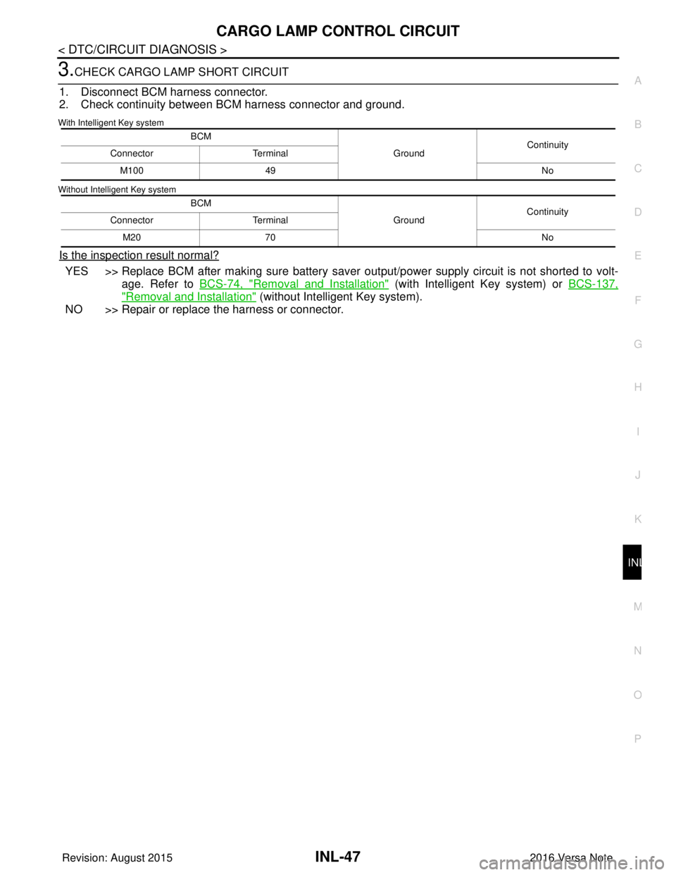
3.CHECK CARGO LAMP SHORT CIRCUIT
1. Disconnect BCM harness connector.
2. Check continuity between BCM harness connector and ground.
With Intelligent Key system
Without Intelligent Key system
Is the inspection result normal?
YES >> Replace BCM after making sure battery saver out put/power supply circuit is not shorted to volt-
age. Refer to BCS-74, "
Removal and Installation" (with Intelligent Key system) or BCS-137,
"Removal and Installation" (without Intelligent Key system).
NO >> Repair or replace the harness or connector.
BCM
GroundContinuity
Connector Terminal
M100 49 No
BCM GroundContinuity
Connector Terminal
M20 70 No
Revision: August 2015 2016 Versa Note
cardiagn.com
Page 2142 of 3641

INL-48
< DTC/CIRCUIT DIAGNOSIS >
PUSH-BUTTON IGNITION SWITCH ILLUMINATION CIRCUIT
PUSH-BUTTON IGNITION SWITCH ILLUMINATION CIRCUIT
DescriptionINFOID:0000000012432748
Provides the power supply and the ground to control the push-button ignition switch illumination.
Component Function CheckINFOID:0000000012432749
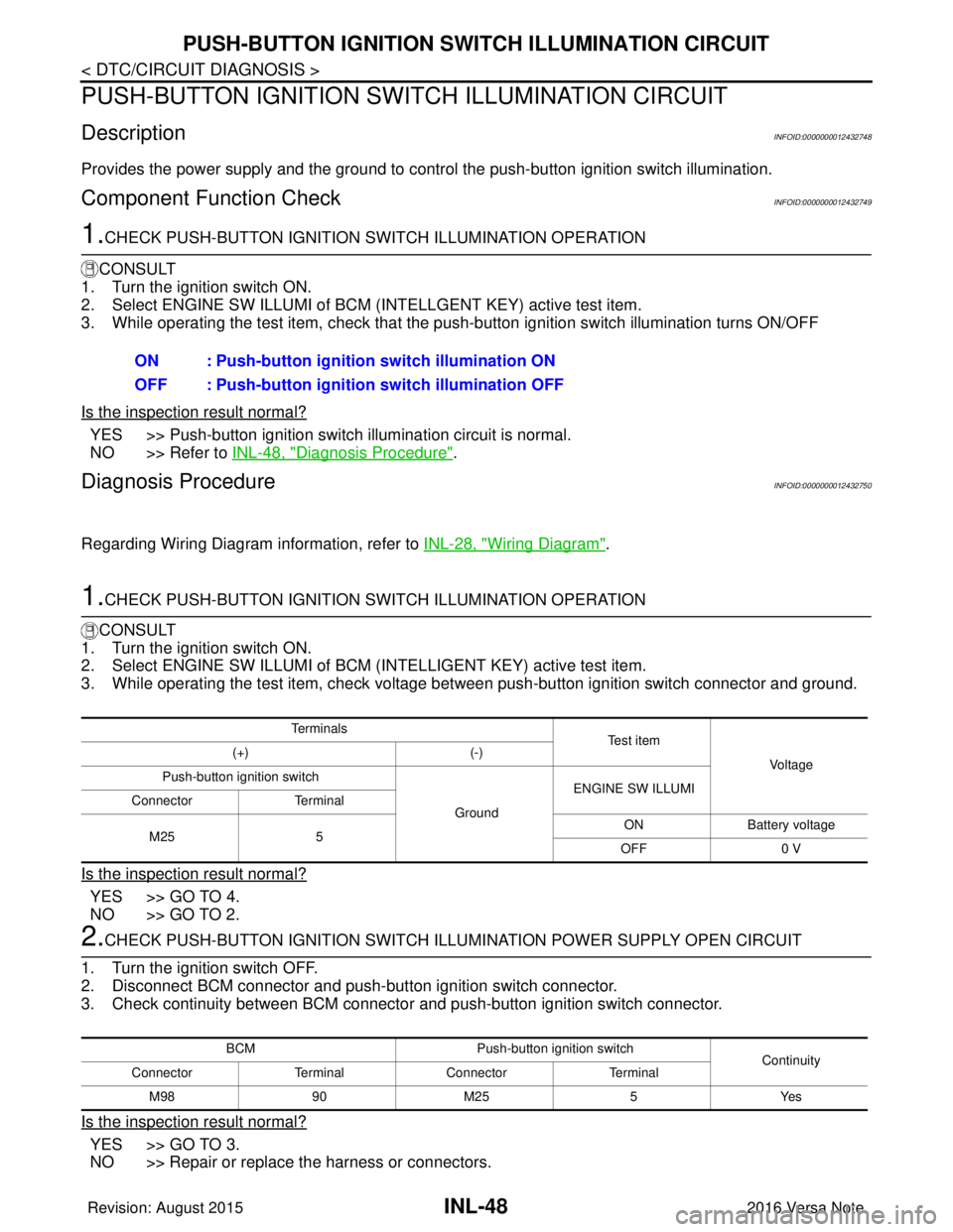
1.CHECK PUSH-BUTTON IGNITION SWITCH ILLUMINATION OPERATION
CONSULT
1. Turn the ignition switch ON.
2. Select ENGINE SW ILLUMI of BCM (I NTELLGENT KEY) active test item.
3. While operating the test item, check that the push-button ignition switch illumination turns ON/OFF
Is the inspection result normal?
YES >> Push-button ignition switch illumination circuit is normal.
NO >> Refer to INL-48, "
Diagnosis Procedure".
Diagnosis ProcedureINFOID:0000000012432750
Regarding Wiring Diagram information, refer to INL-28, "Wiring Diagram".
1.CHECK PUSH-BUTTON IGNITION SWITCH ILLUMINATION OPERATION
CONSULT
1. Turn the ignition switch ON.
2. Select ENGINE SW ILLUMI of BCM (INTELLIGENT KEY) active test item.
3. While operating the test item, check voltage bet ween push-button ignition switch connector and ground.
Is the inspection result normal?
YES >> GO TO 4.
NO >> GO TO 2.
2.CHECK PUSH-BUTTON IGNITION SWITCH ILLUMINATION POWER SUPPLY OPEN CIRCUIT
1. Turn the ignition switch OFF.
2. Disconnect BCM connector and push-button ignition switch connector.
3. Check continuity between BCM connector and push-button ignition switch connector.
Is the inspection result normal?
YES >> GO TO 3.
NO >> Repair or replace the harness or connectors. ON : Push-button ignition switch illumination ON
OFF : Push-button ignition
switch illumination OFF
Te r m i n a l s
Te s t i t e m
Vo l ta g e
(+)
(-)
Push-button ignition switch
GroundENGINE SW ILLUMI
Connector Terminal
M25 5 ON
Battery voltage
OFF 0 V
BCM Push-button ignition switch
Continuity
Connector TerminalConnector Terminal
M 989 0M 25 5 Y es
Revision: August 2015 2016 Versa Note
cardiagn.com
Page 2144 of 3641

INL-50
< SYMPTOM DIAGNOSIS >
INTERIOR LIGHTING SYSTEM SYMPTOMS
SYMPTOM DIAGNOSIS
INTERIOR LIGHTING SYSTEM SYMPTOMS
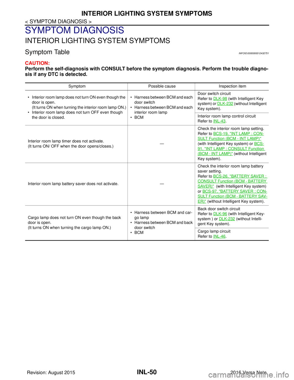
Symptom TableINFOID:0000000012432751
CAUTION:
Perform the self-diagnosis with CONSULT before the symptom diagnosis. Perform the trouble diagno-
sis if any DTC is detected.
Symptom Possible causeInspection item
• Interior room lamp does not turn ON even though the door is open.
(It turns ON when turning the interior room lamp ON.)
• Interior room lamp does not turn OFF even though
the door is closed. • Harness between BCM and each
door switch
• Harness between BCM and each interior room lamp
•BCM Door switch circuit
Refer to DLK-98
(with Intelligent Key
system) or DLK-232
(without Intelligent
Key system).
Interior room lamp control circuit
Refer to INL-43
.
Interior room lamp timer does not activate.
(It turns ON/ OFF when the door opens/closes.) —Check the interior room lamp setting.
Refer to BCS-19, "
INT LAMP : CON-
SULT Function (BCM - INT LAMP)"
(with Intelligent Key system) or BCS-
91, "INT LAMP : CONSULT Function
(BCM - INT LAMP)" (without Intelligent
Key system).
Interior room lamp battery saver does not activate. — Check the interior room lamp battery
saver setting.
Refer to BCS-26, "
BATTERY SAVER :
CONSULT Function (BCM - BATTERY
SAVER)" (with Intelligent Key system)
or BCS-97, "
BATTERY SAVER : CON-
SULT Function (BCM - BATTERY SAV-
ER)" (without Intelligent Key system).
Cargo lamp does not turn ON even though the back
door is open.
(It turns ON when turning the cargo lamp ON.) • Harness between BCM and car-
go lamp
• Harness between BCM and back
door switch
•BCM Back door switch circuit
Refer to DLK-96
(with Intelligent Key-
system ) or DLK-232
(without Intelli-
gent Key system).
Cargo lamp circuit
Refer to INL-46
.
Revision: August 2015 2016 Versa Note
cardiagn.com
Page 2219 of 3641
![NISSAN NOTE 2016 Service Repair Manual LAN
SYSTEMLAN-31
< SYSTEM DESCRIPTION > [CAN]
C
D
E
F
G H
I
J
K L
B A
O P
N
Vehicle speed signal (ABS)
TR R R R R
Brake warning lamp signal TR
Detention switch signal TR
Front wiper stop position sign NISSAN NOTE 2016 Service Repair Manual LAN
SYSTEMLAN-31
< SYSTEM DESCRIPTION > [CAN]
C
D
E
F
G H
I
J
K L
B A
O P
N
Vehicle speed signal (ABS)
TR R R R R
Brake warning lamp signal TR
Detention switch signal TR
Front wiper stop position sign](/manual-img/5/57363/w960_57363-2218.png)
LAN
SYSTEMLAN-31
< SYSTEM DESCRIPTION > [CAN]
C
D
E
F
G H
I
J
K L
B A
O P
N
Vehicle speed signal (ABS)
TR R R R R
Brake warning lamp signal TR
Detention switch signal TR
Front wiper stop position signal TR
High beam status signal RT
Ignition switch ON signal TR
RT
Interlock/PNP switch signal TR
RT
Low beam status signal RT
Push-button ignition switch status signal TR
OD OFF indicator signal RT
RT
Starter control relay signal TR
RT
Starter relay status signal TR
RT
Sleep-ready signal TR
TR
Wake up signal TR
Input shaft revolution signal RT
O/D OFF indicator signal TR
Output shaft revolution signal RT
Shift position signal RT RR
Target gear ratio signal RT
EPS warning lamp signal TR
Overdrive control switch signal RT
Fuel filler cap warning reset signal RT
O/D OFF switch signal RT
Odometer signal TR
Vehicle speed signal (Meter) RR TR
Wake up signal TR
Steering angle sensor signal RR T
A/C ON signal R T
Blower fan ON signal R T
Buzzer output signal RT
Dimmer signal RT
Door switch signal RRT
Engine start operation indicator lamp signal RT
Front wiper request signal RT
High beam request signal RRT
Key warning lamp signal RT
Low beam request signal RRT
Signal name
ECM
ABS
IPDM-E
TCMAV M
EPS
M&A
STRG
BCM
Revision: August 2015 2016 Versa Note
cardiagn.com
Page 2243 of 3641
![NISSAN NOTE 2016 Service Repair Manual LAN
BCM BRANCH LINE CIRCUITLAN-55
< DTC/CIRCUIT DIAGNOSIS > [CAN]
C
D
E
F
G H
I
J
K L
B A
O P
N
BCM BRANCH LINE CIRCUIT
Diagnosis ProcedureINFOID:0000000012433369
1.CHECK CONNECTOR
1. Turn the ignitio NISSAN NOTE 2016 Service Repair Manual LAN
BCM BRANCH LINE CIRCUITLAN-55
< DTC/CIRCUIT DIAGNOSIS > [CAN]
C
D
E
F
G H
I
J
K L
B A
O P
N
BCM BRANCH LINE CIRCUIT
Diagnosis ProcedureINFOID:0000000012433369
1.CHECK CONNECTOR
1. Turn the ignitio](/manual-img/5/57363/w960_57363-2242.png)
LAN
BCM BRANCH LINE CIRCUITLAN-55
< DTC/CIRCUIT DIAGNOSIS > [CAN]
C
D
E
F
G H
I
J
K L
B A
O P
N
BCM BRANCH LINE CIRCUIT
Diagnosis ProcedureINFOID:0000000012433369
1.CHECK CONNECTOR
1. Turn the ignition switch OFF.
2. Disconnect the battery cabl e from the negative terminal.
3. Check the terminals and connectors of the BC M for damage, bend and loose connection (unit side and
connector side).
Is the inspection result normal?
YES >> GO TO 2.
NO >> Repair the terminal and connector.
2.CHECK HARNESS FOR OPEN CIRCUIT
1. Disconnect the connector of BCM.
2. Check the resistance between the BCM harness connector terminals.
- With intelligent key
- Without intelligent key
Is the measurement value within the specification?
YES >> GO TO 3.
NO >> Repair the BCM branch line.
3.CHECK POWER SUPPLY AND GROUND CIRCUIT
Check the power supply and the ground circuit of the BCM. Refer to the following.
• With Intelligent Key system: BCS-67, "
Diagnosis Procedure"
• Without Intelligent Key system: BCS-129, "Diagnosis Procedure"
Is the inspection result normal?
YES (Present error)>>Replace the BCM. Refer to the following.
• With Intelligent Key system: BCS-74, "
Removal and Installation"
• Without Intelligent Key system: BCS-137, "Removal and Installation"
YES (Past error)>>Error was detected in the BCM branch line.
NO >> Repair the power supply and the ground circuit.
BCM harness connector Resistance (Ω)
Connector No. Terminal No.
M97 39 40 Approx. 108 – 132
BCM harness connector Resistance (Ω)
Connector No. Terminal No.
M18 3940Approx. 108 – 132
Revision: August 2015 2016 Versa Note
cardiagn.com
Page 2255 of 3641
![NISSAN NOTE 2016 Service Repair Manual LAN
BCM BRANCH LINE CIRCUITLAN-67
< DTC/CIRCUIT DIAGNOSIS > [CAN SYSTEM (TYPE 501)]
C
D
E
F
G H
I
J
K L
B A
O P
N
BCM BRANCH LINE CIRCUIT
Diagnosis ProcedureINFOID:0000000012785687
1.CHECK CONNECTOR
1 NISSAN NOTE 2016 Service Repair Manual LAN
BCM BRANCH LINE CIRCUITLAN-67
< DTC/CIRCUIT DIAGNOSIS > [CAN SYSTEM (TYPE 501)]
C
D
E
F
G H
I
J
K L
B A
O P
N
BCM BRANCH LINE CIRCUIT
Diagnosis ProcedureINFOID:0000000012785687
1.CHECK CONNECTOR
1](/manual-img/5/57363/w960_57363-2254.png)
LAN
BCM BRANCH LINE CIRCUITLAN-67
< DTC/CIRCUIT DIAGNOSIS > [CAN SYSTEM (TYPE 501)]
C
D
E
F
G H
I
J
K L
B A
O P
N
BCM BRANCH LINE CIRCUIT
Diagnosis ProcedureINFOID:0000000012785687
1.CHECK CONNECTOR
1. Turn the ignition switch OFF.
2. Disconnect the battery cabl e from the negative terminal.
3. Check the terminals and connectors of the BC M for damage, bend and loose connection (unit side and
connector side).
Is the inspection result normal?
YES >> GO TO 2.
NO >> Repair the terminal and connector.
2.CHECK HARNESS FOR OPEN CIRCUIT
1. Disconnect the connector of BCM.
2. Check the resistance between the BCM harness connector terminals.
- With intelligent key
- Without intelligent key
Is the measurement value within the specification?
YES >> GO TO 3.
NO >> Repair the BCM branch line.
3.CHECK POWER SUPPLY AND GROUND CIRCUIT
Check the power supply and the ground circuit of the BCM. Refer to the following.
• With Intelligent Key system: BCS-67, "
Diagnosis Procedure"
• Without Intelligent Key system: BCS-129, "Diagnosis Procedure"
Is the inspection result normal?
YES (Present error)>>Replace the BCM. Refer to the following.
• With Intelligent Key system: BCS-74, "
Removal and Installation"
• Without Intelligent Key system: BCS-137, "Removal and Installation"
YES (Past error)>>Error was detected in the BCM branch line.
NO >> Repair the power supply and the ground circuit.
BCM harness connector Resistance (Ω)
Connector No. Terminal No.
M97 39 40 Approx. 108 – 132
BCM harness connector Resistance (Ω)
Connector No. Terminal No.
M18 3940Approx. 108 – 132
Revision: August 2015 2016 Versa Note
cardiagn.com
Page 2270 of 3641
![NISSAN NOTE 2016 Service Repair Manual LAN-82
< DTC/CIRCUIT DIAGNOSIS >[CAN SYSTEM (TYPE 502)]
BCM BRANCH LINE CIRCUIT
BCM BRANCH LINE CIRCUIT
Diagnosis ProcedureINFOID:0000000012785707
1.CHECK CONNECTOR
1. Turn the ignition switch OFF.
2. NISSAN NOTE 2016 Service Repair Manual LAN-82
< DTC/CIRCUIT DIAGNOSIS >[CAN SYSTEM (TYPE 502)]
BCM BRANCH LINE CIRCUIT
BCM BRANCH LINE CIRCUIT
Diagnosis ProcedureINFOID:0000000012785707
1.CHECK CONNECTOR
1. Turn the ignition switch OFF.
2.](/manual-img/5/57363/w960_57363-2269.png)
LAN-82
< DTC/CIRCUIT DIAGNOSIS >[CAN SYSTEM (TYPE 502)]
BCM BRANCH LINE CIRCUIT
BCM BRANCH LINE CIRCUIT
Diagnosis ProcedureINFOID:0000000012785707
1.CHECK CONNECTOR
1. Turn the ignition switch OFF.
2. Disconnect the battery cable from the negative terminal.
3. Check the terminals and connectors of the BCM for damage, bend and loose connection (unit side and connector side).
Is the inspection result normal?
YES >> GO TO 2.
NO >> Repair the terminal and connector.
2.CHECK HARNESS FOR OPEN CIRCUIT
1. Disconnect the connector of BCM.
2. Check the resistance between the BCM harness connector terminals.
- With intelligent key
- Without intelligent key
Is the measurement value within the specification?
YES >> GO TO 3.
NO >> Repair the BCM branch line.
3.CHECK POWER SUPPLY AND GROUND CIRCUIT
Check the power supply and the ground circuit of the BCM. Refer to the following.
• With Intelligent Key system: BCS-67, "
Diagnosis Procedure"
• Without Intelligent Key system: BCS-129, "Diagnosis Procedure"
Is the inspection result normal?
YES (Present error)>>Replace the BCM. Refer to the following.
• With Intelligent Key system: BCS-74, "
Removal and Installation"
• Without Intelligent Key system: BCS-137, "Removal and Installation"
YES (Past error)>>Error was detected in the BCM branch line.
NO >> Repair the power supply and the ground circuit.
BCM harness connector
Resistance (Ω)
Connector No. Terminal No.
M97 3940Approx. 108 – 132
BCM harness connector Resistance (Ω)
Connector No. Terminal No.
M18 3940Approx. 108 – 132
Revision: August 2015 2016 Versa Note
cardiagn.com
Page 2283 of 3641
![NISSAN NOTE 2016 Service Repair Manual LAN
BCM BRANCH LINE CIRCUITLAN-95
< DTC/CIRCUIT DIAGNOSIS > [CAN SYSTEM (TYPE 503)]
C
D
E
F
G H
I
J
K L
B A
O P
N
BCM BRANCH LINE CIRCUIT
Diagnosis ProcedureINFOID:0000000012785720
1.CHECK CONNECTOR
1 NISSAN NOTE 2016 Service Repair Manual LAN
BCM BRANCH LINE CIRCUITLAN-95
< DTC/CIRCUIT DIAGNOSIS > [CAN SYSTEM (TYPE 503)]
C
D
E
F
G H
I
J
K L
B A
O P
N
BCM BRANCH LINE CIRCUIT
Diagnosis ProcedureINFOID:0000000012785720
1.CHECK CONNECTOR
1](/manual-img/5/57363/w960_57363-2282.png)
LAN
BCM BRANCH LINE CIRCUITLAN-95
< DTC/CIRCUIT DIAGNOSIS > [CAN SYSTEM (TYPE 503)]
C
D
E
F
G H
I
J
K L
B A
O P
N
BCM BRANCH LINE CIRCUIT
Diagnosis ProcedureINFOID:0000000012785720
1.CHECK CONNECTOR
1. Turn the ignition switch OFF.
2. Disconnect the battery cabl e from the negative terminal.
3. Check the terminals and connectors of the BC M for damage, bend and loose connection (unit side and
connector side).
Is the inspection result normal?
YES >> GO TO 2.
NO >> Repair the terminal and connector.
2.CHECK HARNESS FOR OPEN CIRCUIT
1. Disconnect the connector of BCM.
2. Check the resistance between the BCM harness connector terminals.
- With intelligent key
- Without intelligent key
Is the measurement value within the specification?
YES >> GO TO 3.
NO >> Repair the BCM branch line.
3.CHECK POWER SUPPLY AND GROUND CIRCUIT
Check the power supply and the ground circuit of the BCM. Refer to the following.
• With Intelligent Key system: BCS-67, "
Diagnosis Procedure"
• Without Intelligent Key system: BCS-129, "Diagnosis Procedure"
Is the inspection result normal?
YES (Present error)>>Replace the BCM. Refer to the following.
• With Intelligent Key system: BCS-74, "
Removal and Installation"
• Without Intelligent Key system: BCS-137, "Removal and Installation"
YES (Past error)>>Error was detected in the BCM branch line.
NO >> Repair the power supply and the ground circuit.
BCM harness connector Resistance (Ω)
Connector No. Terminal No.
M97 39 40 Approx. 108 – 132
BCM harness connector Resistance (Ω)
Connector No. Terminal No.
M18 3940Approx. 108 – 132
Revision: August 2015 2016 Versa Note
cardiagn.com