2016 NISSAN NOTE brake fluid
[x] Cancel search: brake fluidPage 1627 of 3641
![NISSAN NOTE 2016 Service Repair Manual CO-22
< REMOVAL AND INSTALLATION >[HR16DE]
THERMOSTAT
• Run engine to check for unusual noise and vibration.
NOTE:
If hydraulic pressure inside timing chain tensioner drops after removal and install NISSAN NOTE 2016 Service Repair Manual CO-22
< REMOVAL AND INSTALLATION >[HR16DE]
THERMOSTAT
• Run engine to check for unusual noise and vibration.
NOTE:
If hydraulic pressure inside timing chain tensioner drops after removal and install](/manual-img/5/57363/w960_57363-1626.png)
CO-22
< REMOVAL AND INSTALLATION >[HR16DE]
THERMOSTAT
• Run engine to check for unusual noise and vibration.
NOTE:
If hydraulic pressure inside timing chain tensioner drops after removal and installation, slack in the guide
may generate a pounding noise during and just after engine start. However, this is normal. Noise will stop
after hydraulic pressure rises.
• Warm up engine thoroughly to make sure there is no leaks of fuel, exhaust gas, or any oils/fluids, including
engine oil and engine coolant.
• Bleed air from passages in lines and hoses, such as in cooling system.
• After cooling down engine, again check oil/fluid levels, including engine oil and engine coolant. Refill to spec- ified level, if necessary.
• Summary of the inspection items:
*Power steering fluid, brake fluid, etc. Item
Before starting engine Engine runningAfter engine stopped
Engine coolant LevelLeaks Level
Engine oil LevelLeaks Level
Transmission/
transaxle fluid CVT Models
LeaksLevel/Leaks Leaks
M/T Models Level/Leaks LeaksLevel/Leaks
Other oils and fluids* LevelLeaks Level
Fuel LeaksLeaksLeaks
Exhaust gas —Leaks —
Revision: August 2015 2016 Versa Note
cardiagn.com
Page 1629 of 3641
![NISSAN NOTE 2016 Service Repair Manual CO-24
< REMOVAL AND INSTALLATION >[HR16DE]
WATER OUTLET
Removal and Installation
INFOID:0000000012432149
WARNING:
Do not remove the radiator cap when the engine is hot. Serious burns could occur from NISSAN NOTE 2016 Service Repair Manual CO-24
< REMOVAL AND INSTALLATION >[HR16DE]
WATER OUTLET
Removal and Installation
INFOID:0000000012432149
WARNING:
Do not remove the radiator cap when the engine is hot. Serious burns could occur from](/manual-img/5/57363/w960_57363-1628.png)
CO-24
< REMOVAL AND INSTALLATION >[HR16DE]
WATER OUTLET
Removal and Installation
INFOID:0000000012432149
WARNING:
Do not remove the radiator cap when the engine is hot. Serious burns could occur from high-pressure
engine coolant escaping from the radi ator. Wrap a thick cloth around the radiator cap. Slowly turn it a
quarter of a turn to release built-up pressure. Carefu lly remove radiator cap by turning it all the way.
NOTE:
When removing components such as hoses, tubes/lines, etc. , cap or plug openings to prevent fluid from spill-
ing.
REMOVAL
1. Drain engine coolant. Refer to CO-8, "Draining Engine Coolant".
CAUTION:
• Perform this step when engine is cold.
• Do not spill engine coolant on drive belt.
2. Remove air ducts and air cleaner assembly. Refer to EM-26, "
Removal and Installation".
3. Disconnect radiator hose (upper). Refer to CO-13, "
Exploded View".
4. Disconnect harness connector from engine coolant temperature sensor.
5. Disconnect harness connector from cylinder block heater (Canada only).
6. Disconnect water hoses and heater hoses from water outlet.
7. Remove water outlet.
8. Remove engine coolant temperature sens or from water outlet, if necessary.
9. Remove cylinder block heater from water outlet, if necessary (Canada only).
INSTALLATION
Installation is in the reverse order of removal.
CAUTION:
Do not reuse gasket.
INSPECTION AFTER INSTALLATION
• Before starting engine, check oil/fluid levels, including engine coolant and engine oil. If less than required quantity, fill to the specified level. Refer to MA-11, "
Fluids and Lubricants".
• Use procedure below to check for fuel leaks.
• Turn ignition switch ON (with engine stopped). With fuel pressure applied to fuel piping, check for fuel leaks
at connection points.
• Start engine. With engine speed increased, che ck again for fuel leaks at connection points.
• Run engine to check for unusual noise and vibration. NOTE:
If hydraulic pressure inside timing chain tensioner drops after removal and installation, slack in the guide
may generate a pounding noise during and just after engine start. However, this is normal. Noise will stop
after hydraulic pressure rises.
• Warm up engine thoroughly to make sure there is no leaks of fuel, exhaust gas, or any oils/fluids, including
engine oil and engine coolant.
• Bleed air from passages in lines and hoses, such as in cooling system.
• After cooling down engine, again check oil/fluid levels, including engine oil and engine coolant. Refill to spec- ified level, if necessary.
• Summary of the inspection items:
*Power steering fluid, brake fluid, etc. Item
Before starting engine Engine runningAfter engine stopped
Engine coolant LevelLeaks Level
Engine oil LevelLeaks Level
Transmission/
transaxle fluid CVT Models
LeaksLevel/Leaks Leaks
M/T Models Level/Leaks LeaksLevel/Leaks
Other oils and fluids* LevelLeaks Level
Fuel LeaksLeaksLeaks
Exhaust gas —Leaks —
Revision: August 2015 2016 Versa Note
cardiagn.com
Page 1642 of 3641
![NISSAN NOTE 2016 Service Repair Manual LU-12
< REMOVAL AND INSTALLATION >[HR16DE]
OIL PUMP
3. Loosen the oil pump bolts in the reverse order as shown.
4. Remove oil pump and O-rings.
CAUTION:
• Do not reuse O-rings.
• Do not disassembl NISSAN NOTE 2016 Service Repair Manual LU-12
< REMOVAL AND INSTALLATION >[HR16DE]
OIL PUMP
3. Loosen the oil pump bolts in the reverse order as shown.
4. Remove oil pump and O-rings.
CAUTION:
• Do not reuse O-rings.
• Do not disassembl](/manual-img/5/57363/w960_57363-1641.png)
LU-12
< REMOVAL AND INSTALLATION >[HR16DE]
OIL PUMP
3. Loosen the oil pump bolts in the reverse order as shown.
4. Remove oil pump and O-rings.
CAUTION:
• Do not reuse O-rings.
• Do not disassemble oil pump.
INSTALLATION
1. Install new O-rings on the oil pan (upper) before installing the oil pump. Refer to LU-11, "Exploded View".
CAUTION:
Do not reuse O-rings.
2. Install the oil pump.
3. Tighten the oil pump bolts to specification in the order shown.
4. Install timing chain and oil pump drive chain. Refer to EM-51,
"Removal and Installation".
5. Refill engine with new engine oil. Refer to LU-8, "
Refilling".
INSPECTION AFTER INSTALLATION
• Before starting engine, check oil/fluid levels, including engine coolant and engine oil. If less than required
quantity, fill to the specified level. Refer to MA-11, "
Fluids and Lubricants".
• Use procedure below to check for fuel leaks.
• Turn ignition switch ON (with engine stopped). With fuel pressure applied to fuel piping, check for fuel leaks
at connection points.
• Start engine. With engine speed increased, che ck again for fuel leaks at connection points.
• Run engine to check for unusual noise and vibration. NOTE:
If hydraulic pressure inside timing chain tensioner drops after removal and installation, slack in the guide
may generate a pounding noise during and just after engine start. However, this is normal. Noise will stop
after hydraulic pressure rises.
• Warm up engine thoroughly to make sure there is no leak s of fuel, exhaust gas, or any oils/fluids including
engine oil and engine coolant.
• Bleed air from passages in lines and hoses, such as in cooling system.
• After cooling down engine, again check oil/fluid levels, including engine oil and engine coolant. Refill to spec-
ified level, if necessary.
• Summary of the inspection items:
*Power steering fluid, brake fluid, etc.
AWBIA1122GB
AWBIA1122GB
Item Before starting engine Engine runningAfter engine stopped
Engine coolant LevelLeaks Level
Engine oil LevelLeaks Level
Transmission/
transaxle fluid CVT Models
LeaksLevel/Leaks Leaks
M/T Models Level/Leaks LeaksLevel/Leaks
Other oils and fluids* LevelLeaks Level
Fuel LeaksLeaksLeaks
Exhaust gas —Leaks —
Revision: August 2015 2016 Versa Note
cardiagn.com
Page 1644 of 3641
![NISSAN NOTE 2016 Service Repair Manual LU-14
< REMOVAL AND INSTALLATION >[HR16DE]
OIL COOLER
INSPECTION AFTER REMOVAL
Oil Cooler
Check oil cooler for cracks. Check oil cooler for clogging by blowing compressed air through engine coolant
in NISSAN NOTE 2016 Service Repair Manual LU-14
< REMOVAL AND INSTALLATION >[HR16DE]
OIL COOLER
INSPECTION AFTER REMOVAL
Oil Cooler
Check oil cooler for cracks. Check oil cooler for clogging by blowing compressed air through engine coolant
in](/manual-img/5/57363/w960_57363-1643.png)
LU-14
< REMOVAL AND INSTALLATION >[HR16DE]
OIL COOLER
INSPECTION AFTER REMOVAL
Oil Cooler
Check oil cooler for cracks. Check oil cooler for clogging by blowing compressed air through engine coolant
inlet. If necessary, replace oil cooler.
Relief Valve
Inspect relief valve for movement, cracks and breaks by
pushing the ball. If replacement is necessary, remove
the valve by prying it out using a suitable tool. Install a new valve by tapping it in place.
INSTALLATION
Installation is in the reverse order of removal.
• Ensure that no foreign objects are adhering to the s ealing surfaces of the oil cooler and oil pan (upper).
• Tighten connector bolt after aligning cutout (1) on oil cooler with protrusion (2) on oil pan (upper) side.
CAUTION:
• Do not reuse O-ring.
• Replace relief valve if removed.
INSPECTION AFTER INSTALLATION
• Before starting engine, check oil/fluid levels, including engine coolant and engine oil. If less than required
quantity, fill to the specified level. Refer to MA-11, "
Fluids and Lubricants".
• Use procedure below to check for fuel leaks.
• Turn ignition switch ON (with engine stopped). With fuel pressure applied to fuel piping, check for fuel leaks
at connection points.
• Start engine. With engine speed increased, che ck again for fuel leaks at connection points.
• Run engine to check for unusual noise and vibration. NOTE:
If hydraulic pressure inside timing chain tensioner drops after removal and installation, slack in the guide
may generate a pounding noise during and just after engine start. However, this is normal. Noise will stop
after hydraulic pressure rises.
• Warm up engine thoroughly to make sure there is no leak s of fuel, exhaust gas, or any oils/fluids including
engine oil and engine coolant.
• Bleed air from passages in lines and hoses, such as in cooling system.
• After cooling down engine, again check oil/fluid levels, including engine oil and engine coolant. Refill to spec-
ified level, if necessary.
• Summary of the inspection items:
*Power steering fluid, brake fluid, etc.
AWBIA1139GB
Item Before starting engine Engine runningAfter engine stopped
Engine coolant LevelLeaks Level
Engine oil LevelLeaks Level
Transmission/
transaxle fluid CVT Models
LeaksLevel/Leaks Leaks
M/T Models Level/Leaks LeaksLevel/Leaks
Other oils and fluids* LevelLeaks Level
Fuel LeaksLeaksLeaks
Exhaust gas —Leaks —
Revision: August 2015 2016 Versa Note
cardiagn.com
Page 1836 of 3641

FRONT DRIVE SHAFTFAX-19
< REMOVAL AND INSTALLATION >
CEF
G H
I
J
K L
M A
B
FA X
N
O P
FRONT DRIVE SHAFT
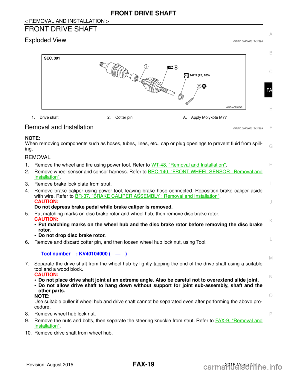
Exploded ViewINFOID:0000000012431898
Removal and InstallationINFOID:0000000012431899
NOTE:
When removing components such as hoses, tubes, lines, etc. , cap or plug openings to prevent fluid from spill-
ing.
REMOVAL
1. Remove the wheel and tire using power tool. Refer to WT-48, "Removal and Installation".
2. Remove wheel sensor and sensor harness. Refer to BRC-140, "
FRONT WHEEL SENSOR : Removal and
Installation".
3. Remove brake lock plate from strut.
4. Remove brake caliper using power tool, leaving brake hose connected. Reposition brake caliper aside with wire. Refer to BR-37, "
BRAKE CALIPER ASSEMBLY : Removal and Installation".
CAUTION:
Do not depress brake pedal while brake caliper is removed.
5. Put matching marks on disc brake rotor and wheel hub, then remove disc brake rotor. CAUTION:
• Put matching marks on the wheel hub and the disc brake rotor before removing the disc brake
rotor.
• Do not drop disc brake rotor.
6. Remove and discard cotter pin, and then loosen wheel hub lock nut, using Tool.
7. Separate the drive shaft from the wheel hub by lightly tapping the end of the drive shaft using a suitable tool and a wood block.
CAUTION:
• Do not place drive shaft joint at an extreme angle. Also be careful not to overextend slide joint.
• Do not allow drive shaft to ha ng down without support for joint sub-assembly, shaft and the
other parts.
NOTE:
Use suitable puller if wheel hub and drive shaft cannot be separated even after performing the above pro-
cedure.
8. Remove wheel hub lock nut.
9. Remove the nuts and bolts, then separate the steering knuckle from strut. Refer to FA X - 9 , "
Removal and
Installation".
10. Remove drive shaft from wheel hub.
1. Drive shaft 2. Cotter pinA. Apply Molykote M77
AWDIA0951GB
Tool number : KV40104000 ( — )
Revision: August 2015 2016 Versa Note
cardiagn.com
Page 1893 of 3641

HOW TO USE THIS MANUALGI-5
< HOW TO USE THIS MANUAL >
C
DE
F
G H
I
J
K L
M B
GI
N
O P
SYMBOLS
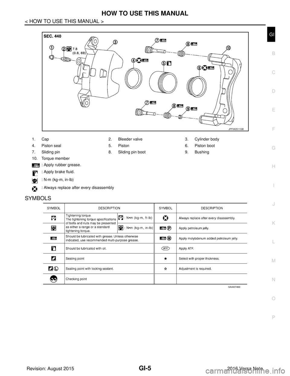
1. Cap 2. Bleeder valve3. Cylinder body
4. Piston seal 5. Piston6. Piston boot
7. Sliding pin 8. Sliding pin boot9. Bushing
10. Torque member
: Apply rubber grease.
: Apply brake fluid.
: N·m (kg-m, in-lb)
: Always replace after every disassembly
JPFIA0511GB
SAIA0749E
Revision: August 2015 2016 Versa Note
cardiagn.com
Page 1902 of 3641

GI-14
< HOW TO USE THIS MANUAL >
ABBREVIATIONS
ABBREVIATIONS
Abbreviation ListINFOID:0000000012433154
The following ABBREVIATIONS are used:
A
B
C
D
ABBREVIATION DESCRIPTION
A/C Air conditioner
A/C Air conditioning
A/F sensor Air fuel ratio sensor A/T Automatic transaxle/transmission
ABS Anti-lock braking system
ACCS Advance climate control system ACL Air cleaner
AP Accelerator pedal
APP Accelerator pedal position
ATF Automatic transmission fluid
AV Audio visual
AVM Around view monitor
AWD All wheel drive
ABBREVIATION DESCRIPTION
BARO Barometric pressure BCI Backup collision intervention
BCM Body control module
BLSD Brake limited slip differential
BPP Brake pedal position
BSI Blind spot intervention
BSW Blind spot warning
ABBREVIATION DESCRIPTION
CKP Crankshaft position
CL Closed loop
CMP Camshaft position
CPP Clutch pedal position
CTP Closed throttle position
CVT Continuously variable transaxle/transmission
ABBREVIATION DESCRIPTION
D
1Drive range first gear
D
2Drive range second gear
D
3Drive range third gear
D
4Drive range fourth gear
DCA Distance control assist
DDS Downhill drive support
DFI Direct fuel injection system
Revision: August 2015 2016 Versa Note
cardiagn.com
Page 1912 of 3641

GI-24
< PRECAUTION >
PRECAUTIONS
General Precautions
INFOID:0000000012433162
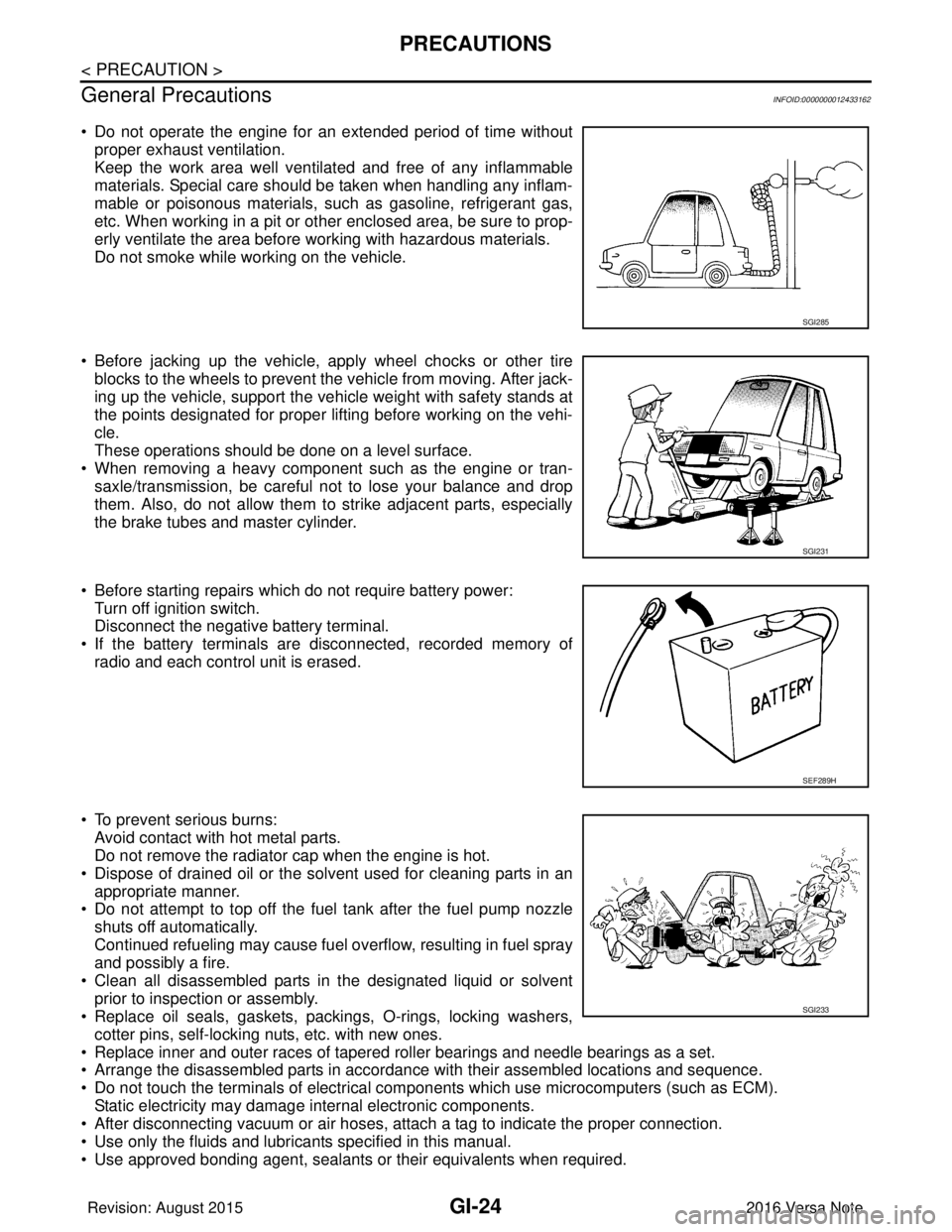
• Do not operate the engine for an extended period of time without proper exhaust ventilation.
Keep the work area well ventilated and free of any inflammable
materials. Special care should be taken when handling any inflam-
mable or poisonous materials, such as gasoline, refrigerant gas,
etc. When working in a pit or other enclosed area, be sure to prop-
erly ventilate the area before working with hazardous materials.
Do not smoke while working on the vehicle.
• Before jacking up the vehicle, apply wheel chocks or other tire blocks to the wheels to prevent the vehicle from moving. After jack-
ing up the vehicle, support the vehicle weight with safety stands at
the points designated for proper lifting before working on the vehi-
cle.
These operations should be done on a level surface.
• When removing a heavy component such as the engine or tran- saxle/transmission, be careful not to lose your balance and drop
them. Also, do not allow them to strike adjacent parts, especially
the brake tubes and master cylinder.
• Before starting repairs which do not require battery power: Turn off ignition switch.
Disconnect the negative battery terminal.
• If the battery terminals are disconnected, recorded memory of radio and each control unit is erased.
• To prevent serious burns: Avoid contact with hot metal parts.
Do not remove the radiator cap when the engine is hot.
• Dispose of drained oil or the solvent used for cleaning parts in an appropriate manner.
• Do not attempt to top off the fuel tank after the fuel pump nozzle
shuts off automatically.
Continued refueling may cause fuel overflow, resulting in fuel spray
and possibly a fire.
• Clean all disassembled parts in the designated liquid or solvent prior to inspection or assembly.
• Replace oil seals, gaskets, packings, O-rings, locking washers,
cotter pins, self-locking nuts, etc. with new ones.
• Replace inner and outer races of tapered roller bearings and needle bearings as a set.
• Arrange the disassembled parts in accordance with their assembled locations and sequence.
• Do not touch the terminals of electrical com ponents which use microcomputers (such as ECM).
Static electricity may damage internal electronic components.
• After disconnecting vacuum or air hoses, atta ch a tag to indicate the proper connection.
• Use only the fluids and lubricants specified in this manual.
• Use approved bonding agent, sealants or their equivalents when required.
SGI285
SGI231
SEF289H
SGI233
Revision: August 2015 2016 Versa Note
cardiagn.com