2016 NISSAN NOTE ECU
[x] Cancel search: ECUPage 3194 of 3641
STC-10
< ECU DIAGNOSIS INFORMATION >
EPS CONTROL UNIT
Protection Function
INFOID:0000000012431947
EPS control unit decreases the output signal to EPS mo tor while extremely using the power steering function
(e.g., full steering) consecutively for protecting EPS motor and EPS control unit (Overload protection control).
While activating overload protection control, the assist torque gradually decreases, and the steering wheel
turning force becomes heavy. The normal assist torque reactivates by no steering.
DTC Inspection Priority ChartINFOID:0000000012431948
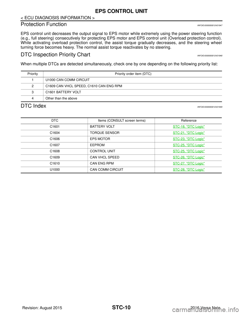
When multiple DTCs are detected simultaneously, c heck one by one depending on the following priority list:
DTC IndexINFOID:0000000012431949
Priority Priority order item (DTC)
1 U1000 CAN COMM CIRCUIT
2 C1609 CAN VHCL SPEED, C1610 CAN ENG RPM
3 C1601 BATTERY VOLT
4 Other than the above
DTC Items (CONSULT screen terms) Reference
C1601 BATTERY VOLT STC-18, "
DTC Logic"
C1604TORQUE SENSOR STC-21, "DTC Logic"
C1606EPS MOTOR STC-23, "DTC Logic"
C1607EEPROM STC-25, "DTC Logic"
C1608CONTROL UNIT STC-25, "DTC Logic"
C1609CAN VHCL SPEED STC-26, "DTC Logic"
C1610CAN ENG RPM STC-27, "DTC Logic"
U1000CAN COMM CIRCUIT STC-28, "DTC Logic"
Revision: August 2015 2016 Versa Note
cardiagn.com
Page 3230 of 3641
STEERING COLUMNST-9
< REMOVAL AND INSTALLATION >
C
DE
F
H I
J
K L
M A
B
ST
N
O P
STEERING COLUMN
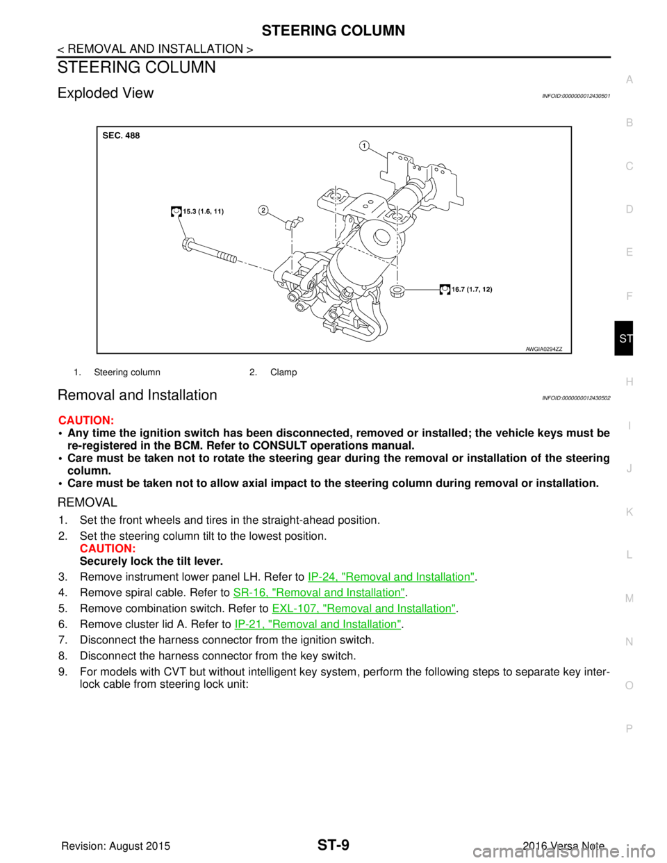
Exploded ViewINFOID:0000000012430501
Removal and InstallationINFOID:0000000012430502
CAUTION:
• Any time the ignition switch has been disconnected, removed or installed; the vehicle keys must be
re-registered in the BCM. Refer to CONSULT operations manual.
• Care must be taken not to rotate the steering gear during the removal or inst allation of the steering
column.
• Care must be taken not to allow axial impact to the steering column during removal or installation.
REMOVAL
1. Set the front wheels and tires in the straight-ahead position.
2. Set the steering column tilt to the lowest position.
CAUTION:
Securely lock the tilt lever.
3. Remove instrument lower panel LH. Refer to IP-24, "
Removal and Installation".
4. Remove spiral cable. Refer to SR-16, "
Removal and Installation".
5. Remove combination switch. Refer to EXL-107, "
Removal and Installation".
6. Remove cluster lid A. Refer to IP-21, "
Removal and Installation".
7. Disconnect the harness connector from the ignition switch.
8. Disconnect the harness connector from the key switch.
9. For models with CVT but without intelligent key system , perform the following steps to separate key inter-
lock cable from steering lock unit:
1. Steering column 2. Clamp
AWGIA0294ZZ
Revision: August 2015 2016 Versa Note
cardiagn.com
Page 3231 of 3641
ST-10
< REMOVAL AND INSTALLATION >
STEERING COLUMN
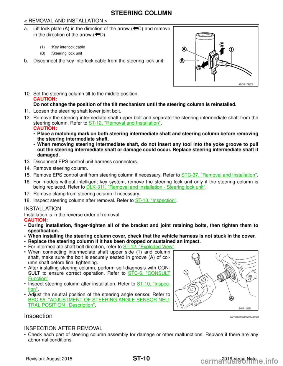
a. Lift lock plate (A) in the direction of the arrow ( C) and removein the direction of the arrow ( D).
b. Disconnect the key interlock cable from the steering lock unit.
10. Set the steering column tilt to the middle position. CAUTION:
Do not change the position of the tilt mechanism until the steering column is reinstalled.
11. Loosen the steering shaft lower joint bolt.
12. Remove the steering intermediate shaft upper bolt and separate the steering intermediate shaft from the
steering column. Refer to ST-12, "
Removal and Installation".
CAUTION:
• Place a matching mark on both steering interme diate shaft and steering column before removing
the steering intermediate shaft.
• When removing steering intermedi ate shaft, do not insert any tool into the yoke groove to pull
out the steering intermediate shaft or damage could occur. Replace steering intermediate shaft if
damaged.
13. Disconnect EPS control unit harness connectors.
14. Remove steering column.
15. Remove EPS control unit from steering column if necessary. Refer to STC-37, "
Removal and Installation".
16. For models without intelligent key system, remove the steering lock unit only if the steering column is being replaced. Refer to DLK-311, "
Removal and Installation - Steering lock unit".
17. Remove clamp from steering column if necessary.
18. Inspect steering column after removal. Refer to ST-10, "
Inspection".
INSTALLATION
Installation is in the reverse order of removal.
CAUTION:
• During installation, finger-tighten all of the bracket and joint retaining bolts, then tighten them to
specification.
• When installing the steering colu mn cover, check that the vehicle harness is not stuck in the cover.
• Replace the steering column if it has been dropped or sustained an impact.
• For intermediate shaft bolt direction, refer to ST-12, "
Exploded View".
• When connecting intermediate shaft upper side (1) and column shaft, make sure the bolt is securely seated in groove (A) of col-
umn shaft before final tightening.
• After installing steering column, perform self-diagnosis with CON- SULT to ensure correct operation. Refer to STC-6, "
CONSULT
Function".
• Inspect steering column after installation. Refer to ST-10, "
Inspec-
tion".
• Adjust the neutral position of the steering angle sensor. Refer to
BRC-55, "
ADJUSTMENT OF STEERI NG ANGLE SENSOR NEU-
TRAL POSITION : Description".
InspectionINFOID:0000000012430503
INSPECTION AFTER REMOVAL
• Check each part of steering column assembly for damage or other malfunctions. Replace if there are any
abnormal conditions.
(1) :Key interlock cable
(B) :Steering lock unit
JSDIA1798ZZ
SGIA1295E
Revision: August 2015 2016 Versa Note
cardiagn.com
Page 3233 of 3641
ST-12
< REMOVAL AND INSTALLATION >
STEERING SHAFT
STEERING SHAFT
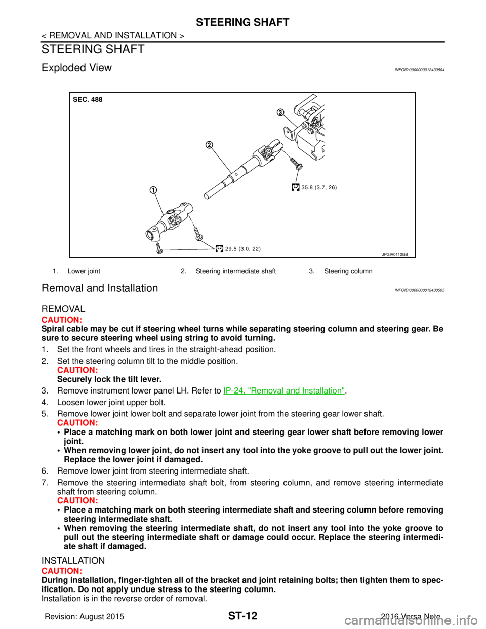
Exploded ViewINFOID:0000000012430504
Removal and InstallationINFOID:0000000012430505
REMOVAL
CAUTION:
Spiral cable may be cut if steering wheel turns while separating steering column and steering gear. Be
sure to secure steering wheel us ing string to avoid turning.
1. Set the front wheels and tires in the straight-ahead position.
2. Set the steering column tilt to the middle position. CAUTION:
Securely lock the tilt lever.
3. Remove instrument lower panel LH. Refer to IP-24, "
Removal and Installation".
4. Loosen lower joint upper bolt.
5. Remove lower joint lower bolt and separate lower joint from the steering gear lower shaft. CAUTION:
• Place a matching mark on both lower joint and st eering gear lower shaft before removing lower
joint.
• When removing lower joint, do not insert any tool into the yoke groove to pull out the lower joint.
Replace the lower joint if damaged.
6. Remove lower joint from steering intermediate shaft.
7. Remove the steering intermediate shaft bolt, from steering column, and remove steering intermediate
shaft from steering column.
CAUTION:
• Place a matching mark on both steering interme diate shaft and steering column before removing
steering intermediate shaft.
• When removing the steering intermediate shaft, do not insert any tool into the yoke groove to pull out the steering intermediate shaft or dama ge could occur. Replace the steering intermedi-
ate shaft if damaged.
INSTALLATION
CAUTION:
During installation, finger-tighten all of the bracket and joint retainin g bolts; then tighten them to spec-
ification. Do not ap ply undue stress to the steering column.
Installation is in the reverse order of removal.
1. Lower joint 2. Steering intermediate shaft 3. Steering column
JPGIA0112GB
Revision: August 2015 2016 Versa Note
cardiagn.com
Page 3234 of 3641
STEERING SHAFTST-13
< REMOVAL AND INSTALLATION >
C
DE
F
H I
J
K L
M A
B
ST
N
O P
• Before installation, check that steering column tilt is in the middle position.
• For intermediate shaft bolt, and lower joint bolt direction, refer to ST-12, "
Exploded View".
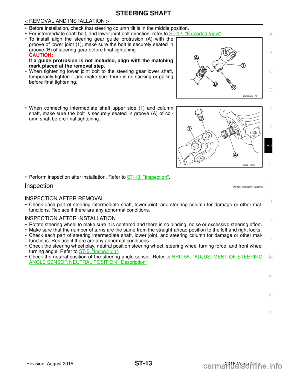
• To install align the steering gear guide protrusion (A) with the
groove of lower joint (1), make sure the bolt is securely seated in
groove (B) of steering gear before final tightening.
CAUTION:
If a guide protrusion is not included, align with the matching
mark placed at the removal step.
• When tightening lower joint bolt to the steering gear lower shaft,
temporarily tighten it and make sure there is no sticking or galling
before final tightening.
• When connecting intermediate shaft upper side (1) and column shaft, make sure the bolt is securely seated in groove (A) of col-
umn shaft before final tightening.
• Perform inspection after installation. Refer to ST-13, "
Inspection".
InspectionINFOID:0000000012430506
INSPECTION AFTER REMOVAL
• Check each part of steering intermediate shaft, lowe r joint, and steering column for damage or other mal-
functions. Replace if there are any abnormal conditions.
INSPECTION AFTER INSTALLATION
• Rotate steering wheel to make sure it is centered and there is no binding, noise or excessive steering effort.
• Make sure that the number of turns are the same from the straight-ahead position to the left and right locks.
• Check each part of steering intermediate shaft, lowe r joint, and steering column for damage or other mal-
functions. Replace if there are any abnormal conditions.
• Check the steering wheel play, neutral position steeri ng wheel, steering wheel turning force, and front wheel
turning angle. Refer to ST-5, "
Inspection".
• Check the neutral position of the steering angle sensor. Refer to BRC-55, "
ADJUSTMENT OF STEERING
ANGLE SENSOR NEUTRAL POSITION : Description".
JPGIA0041ZZ
SGIA1295E
Revision: August 2015 2016 Versa Note
cardiagn.com
Page 3235 of 3641
ST-14
< REMOVAL AND INSTALLATION >
STEERING GEAR AND LINKAGE
STEERING GEAR AND LINKAGE
Exploded ViewINFOID:0000000012430507
Removal and InstallationINFOID:0000000012430508
CAUTION:
• Spiral cable may be cut if steering wheel turns while separating steering column and steering gear;Always secure the steering wheel using string to avoid turning.
• Place a matching mark on both lower joint and steering gear before removing lower joint.
• When removing lower joint, do no t place any tool into the yoke groove to pull out the lower joint.
Replace the lower joint if damaged.
REMOVAL
1. Set the front wheels and tires in the straight-ahead position.
2. Set the steering column tilt to the middle position. CAUTION:
Securely lock the tilt lever.
3. Remove front suspension member. Refer to FSU-14, "
Removal and Installation".
4. Remove the steering gear bolts and nuts and separate the steering gear from the front suspension mem- ber.
5. Separate cowl seal from steering gear if necessary.
INSTALLATION
Installation is in the reverse order of removal.
CAUTION:
• During installation, finger-tighten all of the bracket and joint retaining bolts; then tighten them to
specification. Do not apply undue stress to the steering column.
• The guide protrusion is not required to be reinstalled.
• Before installation, check that the steering column tilt is in the middle position.
• Clean mating surface on the body side of cowl seal when installing steering gear assembly.
• Inspect steering gear after installation. Refer to ST-14, "
Inspection".
InspectionINFOID:0000000012430509
INSPECTION AFTER REMOVAL
• Check each part of steering gear for damage or other malfunctions. Replace if there are any abnormal con-
ditions. Refer to ST-18, "
Inspection".
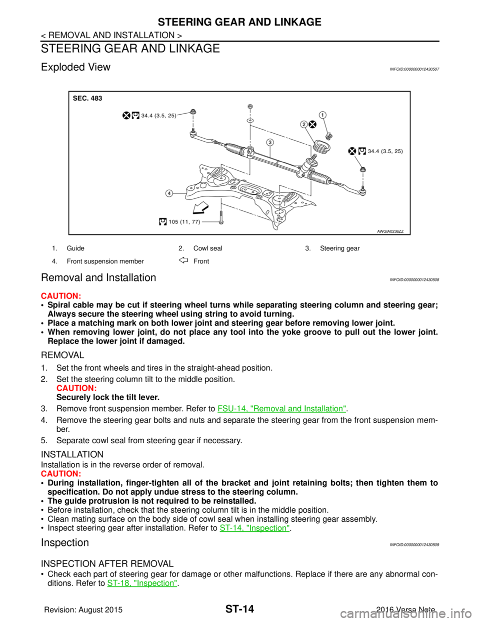
1. Guide 2. Cowl seal3. Steering gear
4. Front suspension member Front
AWGIA0236ZZ
Revision: August 2015 2016 Versa Note
cardiagn.com
Page 3244 of 3641
TM-3
CEF
G H
I
J
K L
M A
B
TM
N
O P
SHIFT CONTROL ..................................................
....
82
SHIFT CONTROL : System Description .................83
SELECT CONTROL .............................................. ....84
SELECT CONTROL : System Description ..............85
LOCK-UP CONTROL ............................................ ....85
LOCK-UP CONTROL : System Description ............86
IDLE NEUTRAL CONTROL .................................. ....86
IDLE NEUTRAL CONTROL : System Description ....87
ON BOARD DIAGNOSTIC (OBD) SYSTEM ......90
Description .......................................................... ....90
Function of OBD ......................................................90
DIAGNOSIS SYSTEM (TCM) .............................91
DIAGNOSIS DESCRIPTION ................................. ....91
DIAGNOSIS DESCRIPTION : 1 Trip Detection Di-
agnosis and 2 Trip Detect ion Diagnosis ..................
91
DIAGNOSIS DESCRIPTION : DTC and DTC of
1st Trip ................................................................ ....
91
DIAGNOSIS DESCRIPTION : Malfunction Indica-
tor Lamp (MIL) .........................................................
91
DIAGNOSIS DESCRIPTION : Counter System ......91
CONSULT Function ............................................ ....93
ECU DIAGNOSIS INFORMATION ..............99
TCM ................................................................ ....99
Reference Value ................................................. ....99
Fail-safe ................................................................106
Protection Control .................................................109
DTC Inspection Priority Chart ............................. ..109
DTC Index ........................................................... ..110
WIRING DIAGRAM ....................................112
CVT CONTROL SYST EM ................................112
Wiring Diagram ................................................... ..112
CVT SHIFT LOCK SYSTEM ............................119
Wiring Diagram ................................................... ..119
BASIC INSPECTION .................................122
DIAGNOSIS AND REPAIR WORK FLOW .... ..122
Flowchart of Trouble Diagnosis ........................... ..122
Question sheet ......................................................123
ADDITIONAL SERVICE WHEN REPLACING
TCM ..................................................................
125
Description .......................................................... ..125
Work Procedure ....................................................125
ADDITIONAL SERVICE WHEN REPLACING
CONTROL VALVE OR TRANSAXLE ASSEM-
BLY ...................................................................
127
Description .......................................................... ..127
Work Procedure ....................................................127
CALIBRATION OF G SENSOR .......................130
Description ........................................................... ..130
Work Procedure .....................................................130
STALL TEST ...................................................131
Work Procedure .....................................................131
LINE PRESSURE TEST ..................................132
Work Procedure .....................................................132
CVT POSITION ...............................................133
Inspection ..............................................................133
Adjustment .............................................................133
HOW TO ERASE PERMANENT DTC ............134
Description .............................................................134
DTC/CIRCUIT DIAGNOSIS .......................135
U0073 COMMUNICATION BUS A OFF .........135
Description ........................................................... ..135
DTC Logic ..............................................................135
Diagnosis Procedure .............................................135
U0100 LOST COMMUNICATION (ECM A) ....136
Description .............................................................136
DTC Logic ..............................................................136
Diagnosis Procedure .............................................136
U0140 LOST COMMUNICATION (BCM) ........137
Description .............................................................137
DTC Logic ..............................................................137
Diagnosis Procedure .............................................137
U0141 LOST COMMUNICATION (BCM A) ....138
Description .............................................................138
DTC Logic ..............................................................138
Diagnosis Procedure .............................................138
U0155 LOST COMMUNICATION (IPC) ..........139
Description .............................................................139
DTC Logic ..............................................................139
Diagnosis Procedure .............................................139
U0300 CAN COMMUNICATION DATA ..........140
Description .............................................................140
DTC Logic ..............................................................140
Diagnosis Procedure .............................................140
U1000 CAN COMM CIRCUIT .........................141
Description .............................................................141
DTC Logic ..............................................................141
Diagnosis Procedure .............................................141
U1117 LOST COMMUNICATION (ABS) ........142
Description .............................................................142
DTC Logic ..............................................................142
Diagnosis Procedure .............................................142
P062F EEPROM ..............................................143
Description .............................................................143
DTC Logic ..............................................................143
Diagnosis Procedure .............................................143
Revision: August 2015 2016 Versa Note
cardiagn.com
Page 3248 of 3641
![NISSAN NOTE 2016 Service Repair Manual PRECAUTIONSTM-7
< PRECAUTION > [5MT: RS5F91R]
C
EF
G H
I
J
K L
M A
B
TM
N
O P
PRECAUTION
PRECAUTIONS
Precaution for Supplemental Restraint System (SRS) "AIR BAG" and "SEAT BELT
PRE-TENSIONER"
INFOID NISSAN NOTE 2016 Service Repair Manual PRECAUTIONSTM-7
< PRECAUTION > [5MT: RS5F91R]
C
EF
G H
I
J
K L
M A
B
TM
N
O P
PRECAUTION
PRECAUTIONS
Precaution for Supplemental Restraint System (SRS) "AIR BAG" and "SEAT BELT
PRE-TENSIONER"
INFOID](/manual-img/5/57363/w960_57363-3247.png)
PRECAUTIONSTM-7
< PRECAUTION > [5MT: RS5F91R]
C
EF
G H
I
J
K L
M A
B
TM
N
O P
PRECAUTION
PRECAUTIONS
Precaution for Supplemental Restraint System (SRS) "AIR BAG" and "SEAT BELT
PRE-TENSIONER"
INFOID:0000000012430936
The Supplemental Restraint System such as “AIR BAG” and “SEAT BELT PRE-TENSIONER”, used along
with a front seat belt, helps to reduce the risk or severi ty of injury to the driver and front passenger for certain
types of collision. Information necessary to service the system safely is included in the SR and SB section of
this Service Manual.
WARNING:
• To avoid rendering the SRS inoper ative, which could increase the risk of personal injury or death in
the event of a collision which would result in air bag inflation, all maintenance must be performed by
an authorized NISSAN/INFINITI dealer.
• Improper maintenance, including in correct removal and installation of the SRS, can lead to personal
injury caused by unintentional act ivation of the system. For removal of Spiral Cable and Air Bag
Module, see the SR section.
• Do not use electrical test equipm ent on any circuit related to the SRS unless instructed to in this
Service Manual. SRS wiring harnesses can be identi fied by yellow and/or orange harnesses or har-
ness connectors.
PRECAUTIONS WHEN USING POWER TOOLS (AIR OR ELECTRIC) AND HAMMERS
WARNING:
• When working near the Airbag Diagnosis Sensor Un it or other Airbag System sensors with the Igni-
tion ON or engine running, DO NOT use air or el ectric power tools or strike near the sensor(s) with a
hammer. Heavy vibration could activate the sensor( s) and deploy the air bag(s), possibly causing
serious injury.
• When using air or electric power tools or hammers, always switch the Ignition OFF, disconnect the
battery and wait at least three mi nutes before performing any service.
General PrecautionsINFOID:0000000012430937
CAUTION:
• Do not reuse CSC (Concentric Sl ave Cylinder). CSC slides back to th e original position every time
when removing transaxle assembly. At this time, du st on the sliding parts may damage the seal of
CSC and may cause clutch fluid leakage. Refer to CL-17, "
Removal and Installation".
• Do not reuse transaxle gear oi l, once it has been drained.
• Check oil level or replace gear oil with vehicle on level surface.
• During removal or installation, keep insi de of transaxle clear of dust or dirt.
• Check for the correct installation alignment prior to removal or disassembly. If matching marks are
required, be certain they do not interfer e with the function of the parts marked.
• In principle, tighten bolts or nu ts gradually in several steps workin g diagonally from inside to out-
side. If tightening sequence is specified, use it.
• Do not damage sliding surfaces and mating surfaces.
Precaution for WorkINFOID:0000000012430938
• When removing or disassembling each component, be ca reful not to damage or deform it. If a component
may be subject to interference, be sure to protect it with a shop cloth.
• When removing (disengaging) components with a screwdriver or similar tool, be sure to wrap the component with a shop cloth or vinyl tape to protect it.
• Protect the removed parts with a shop cloth and prevent them from being dropped.
• Replace a deformed or damaged clip.
• If a part is specified as a non-reusabl e part, always replace it with a new one.
• Be sure to tighten bolts and nuts securely to the specified torque.
• After installation is complete, be sure to check that each part works properly.
• Follow the steps below to clean components:
- Water soluble dirt:
• Dip a soft cloth into lukewarm water, wring the water out of the cloth and wipe the dirty area.
• Then rub with a soft, dry cloth.
Revision: August 2015 2016 Versa Note
cardiagn.com