2016 NISSAN NOTE radio
[x] Cancel search: radioPage 585 of 3641
![NISSAN NOTE 2016 Service Repair Manual PEDAL VIBRATION OR ABS OPERATION SOUND OCCURS
BRC-137
< SYMPTOM DIAGNOSIS > [VDC/TCS/ABS]
C
D
E
G H
I
J
K L
M A
B
BRC
N
O P
PEDAL VIBRATION OR ABS OPERATION SOUND OCCURS
Diagnosis ProcedureINFOID:000 NISSAN NOTE 2016 Service Repair Manual PEDAL VIBRATION OR ABS OPERATION SOUND OCCURS
BRC-137
< SYMPTOM DIAGNOSIS > [VDC/TCS/ABS]
C
D
E
G H
I
J
K L
M A
B
BRC
N
O P
PEDAL VIBRATION OR ABS OPERATION SOUND OCCURS
Diagnosis ProcedureINFOID:000](/manual-img/5/57363/w960_57363-584.png)
PEDAL VIBRATION OR ABS OPERATION SOUND OCCURS
BRC-137
< SYMPTOM DIAGNOSIS > [VDC/TCS/ABS]
C
D
E
G H
I
J
K L
M A
B
BRC
N
O P
PEDAL VIBRATION OR ABS OPERATION SOUND OCCURS
Diagnosis ProcedureINFOID:0000000012430922
CAUTION:
Under the following conditions, ABS is activated an d vibration is felt when brake pedal is lightly
depressed (just place a foot on it). However, this is normal.
• When shifting gears
• When driving on slippery road
• During cornering at high speed
• When passing over bumps or grooves [approximately 50 mm (1.97 in) or more]
• When pulling away just after starting engine [at approximately 10 km/h (6 MPH) or higher]
1.SYMPTOM CHECK 1
Check that there are pedal vibrat ions when the engine is started.
Do symptoms occur?
YES >> GO TO 2.
NO >> Inspect the brake pedal.
2.SYMPTOM CHECK 2
Check that there are ABS operation noises when the engine is started.
Do symptoms occur?
YES >> GO TO 3.
NO >> Perform “Self Diagnostic Result”. Refer to BRC-31, "
CONSULT Function (ABS)".
3.SYMPTOM CHECK 3
Check symptoms when electrical component (headlamps, etc.) switches are operated.
Do symptoms occur?
YES >> Check if there is a radio, antenna, antenna lead wire, or wiring close to the control unit. If there is,
move it farther away.
NO >> Inspection End.
Revision: August 2015 2016 Versa Note
cardiagn.com
Page 698 of 3641
![NISSAN NOTE 2016 Service Repair Manual PRECAUTIONSDLK-9
< PRECAUTION > [WITH INTELLIGENT KEY SYSTEM]
C
D
E
F
G H
I
J
L
M A
B
DLK
N
O P
PRECAUTION
PRECAUTIONS
Precaution for Supplemental Restraint System (SRS) "AIR BAG" and "SEAT BELT
PRE NISSAN NOTE 2016 Service Repair Manual PRECAUTIONSDLK-9
< PRECAUTION > [WITH INTELLIGENT KEY SYSTEM]
C
D
E
F
G H
I
J
L
M A
B
DLK
N
O P
PRECAUTION
PRECAUTIONS
Precaution for Supplemental Restraint System (SRS) "AIR BAG" and "SEAT BELT
PRE](/manual-img/5/57363/w960_57363-697.png)
PRECAUTIONSDLK-9
< PRECAUTION > [WITH INTELLIGENT KEY SYSTEM]
C
D
E
F
G H
I
J
L
M A
B
DLK
N
O P
PRECAUTION
PRECAUTIONS
Precaution for Supplemental Restraint System (SRS) "AIR BAG" and "SEAT BELT
PRE-TENSIONER"
INFOID:0000000012429960
The Supplemental Restraint System such as “AIR BAG” and “SEAT BELT PRE-TENSIONER”, used along
with a front seat belt, helps to reduce the risk or severi ty of injury to the driver and front passenger for certain
types of collision. Information necessary to service the system safely is included in the SR and SB section of
this Service Manual.
WARNING:
• To avoid rendering the SRS inoper ative, which could increase the risk of personal injury or death in
the event of a collision which would result in air bag inflation, all maintenance must be performed by
an authorized NISSAN/INFINITI dealer.
• Improper maintenance, including in correct removal and installation of the SRS, can lead to personal
injury caused by unintentional act ivation of the system. For removal of Spiral Cable and Air Bag
Module, see the SR section.
• Do not use electrical test equipm ent on any circuit related to the SRS unless instructed to in this
Service Manual. SRS wiring harnesses can be identi fied by yellow and/or orange harnesses or har-
ness connectors.
PRECAUTIONS WHEN USING POWER TOOLS (AIR OR ELECTRIC) AND HAMMERS
WARNING:
• When working near the Airbag Diagnosis Sensor Un it or other Airbag System sensors with the Igni-
tion ON or engine running, DO NOT use air or el ectric power tools or strike near the sensor(s) with a
hammer. Heavy vibration could activate the sensor( s) and deploy the air bag(s), possibly causing
serious injury.
• When using air or electric power tools or hammers, always switch the Ignition OFF, disconnect the
battery and wait at least three mi nutes before performing any service.
Procedure without Cowl Top CoverINFOID:0000000012429961
When performing the procedure after removing cowl top cover, cover
the lower end of windshield with urethane, etc. to prevent damage to
the windshield.
Precaution for Servicing Doors and LocksINFOID:0000000012429962
WARNING:
Radio waves could adversely affect electric medical equipment. Those who use a pacemaker should
contact the electric medical equipment manufacturer for the possible influences before use,
• After removing and installing the opening/closing parts, be sure to carry out fitting adjustments to check their operation.
• Check the lubrication level, damage, and wear of each part. If necessary, grease or replace it.
• When removing or disassembling each component, be ca reful not to damage or deform it. If a component
may be subject to interference, be sure to protect it with a shop cloth.
• When removing (disengaging) components with a screwdriver or similar tool, be sure to wrap the component
with a shop cloth or vinyl tape to protect it.
• Protect the removed parts with a shop cloth and prevent them from being dropped.
• Replace a deformed or damaged clip.
• If a part is specified as a non-reusabl e part, always replace it with a new one.
PIIB3706J
Revision: August 2015 2016 Versa Note
cardiagn.com
Page 878 of 3641
![NISSAN NOTE 2016 Service Repair Manual PRECAUTIONSDLK-189
< PRECAUTION > [WITHOUT INTELLIGENT KEY SYSTEM]
C
D
E
F
G H
I
J
L
M A
B
DLK
N
O P
PRECAUTION
PRECAUTIONS
Precaution for Supplemental Restraint System (SRS) "AIR BAG" and "SEAT BELT NISSAN NOTE 2016 Service Repair Manual PRECAUTIONSDLK-189
< PRECAUTION > [WITHOUT INTELLIGENT KEY SYSTEM]
C
D
E
F
G H
I
J
L
M A
B
DLK
N
O P
PRECAUTION
PRECAUTIONS
Precaution for Supplemental Restraint System (SRS) "AIR BAG" and "SEAT BELT](/manual-img/5/57363/w960_57363-877.png)
PRECAUTIONSDLK-189
< PRECAUTION > [WITHOUT INTELLIGENT KEY SYSTEM]
C
D
E
F
G H
I
J
L
M A
B
DLK
N
O P
PRECAUTION
PRECAUTIONS
Precaution for Supplemental Restraint System (SRS) "AIR BAG" and "SEAT BELT
PRE-TENSIONER"
INFOID:0000000012430150
The Supplemental Restraint System such as “AIR BAG” and “SEAT BELT PRE-TENSIONER”, used along
with a front seat belt, helps to reduce the risk or severi ty of injury to the driver and front passenger for certain
types of collision. Information necessary to service the system safely is included in the SR and SB section of
this Service Manual.
WARNING:
• To avoid rendering the SRS inoper ative, which could increase the risk of personal injury or death in
the event of a collision which would result in air bag inflation, all maintenance must be performed by
an authorized NISSAN/INFINITI dealer.
• Improper maintenance, including in correct removal and installation of the SRS, can lead to personal
injury caused by unintentional act ivation of the system. For removal of Spiral Cable and Air Bag
Module, see the SR section.
• Do not use electrical test equipm ent on any circuit related to the SRS unless instructed to in this
Service Manual. SRS wiring harnesses can be identi fied by yellow and/or orange harnesses or har-
ness connectors.
PRECAUTIONS WHEN USING POWER TOOLS (AIR OR ELECTRIC) AND HAMMERS
WARNING:
• When working near the Airbag Diagnosis Sensor Un it or other Airbag System sensors with the Igni-
tion ON or engine running, DO NOT use air or el ectric power tools or strike near the sensor(s) with a
hammer. Heavy vibration could activate the sensor( s) and deploy the air bag(s), possibly causing
serious injury.
• When using air or electric power tools or hammers, always switch the Ignition OFF, disconnect the
battery and wait at least three mi nutes before performing any service.
Procedure without Cowl Top CoverINFOID:0000000012430151
When performing the procedure after removing cowl top cover, cover
the lower end of windshield with urethane, etc. to prevent damage to
the windshield.
Precaution for Servicing Doors and LocksINFOID:0000000012430152
WARNING:
Radio waves could adversely affect electric medical equipment. Those who use a pacemaker should
contact the electric medical equipment manufacturer for the possible influences before use,
• After removing and installing the opening/closing parts, be sure to carry out fitting adjustments to check their operation.
• Check the lubrication level, damage, and wear of each part. If necessary, grease or replace it.
• When removing or disassembling each component, be ca reful not to damage or deform it. If a component
may be subject to interference, be sure to protect it with a shop cloth.
• When removing (disengaging) components with a screwdriver or similar tool, be sure to wrap the component
with a shop cloth or vinyl tape to protect it.
• Protect the removed parts with a shop cloth and prevent them from being dropped.
• Replace a deformed or damaged clip.
• If a part is specified as a non-reusabl e part, always replace it with a new one.
PIIB3706J
Revision: August 2015 2016 Versa Note
cardiagn.com
Page 1138 of 3641
![NISSAN NOTE 2016 Service Repair Manual PRECAUTIONSEC-11
< PRECAUTION > [HR16DE]
C
D
E
F
G H
I
J
K L
M A
EC
NP
O
•
When installing C.B. ham radio or a mobile phone, be sure to
observe the following as it may adversely affect electronic
co NISSAN NOTE 2016 Service Repair Manual PRECAUTIONSEC-11
< PRECAUTION > [HR16DE]
C
D
E
F
G H
I
J
K L
M A
EC
NP
O
•
When installing C.B. ham radio or a mobile phone, be sure to
observe the following as it may adversely affect electronic
co](/manual-img/5/57363/w960_57363-1137.png)
PRECAUTIONSEC-11
< PRECAUTION > [HR16DE]
C
D
E
F
G H
I
J
K L
M A
EC
NP
O
•
When installing C.B. ham radio or a mobile phone, be sure to
observe the following as it may adversely affect electronic
control systems depending on installation location.
- Keep the antenna as far as possible from the electronic con-
trol units.
- Keep the antenna feeder line more than 20 cm (8 in) away
from the harness of electronic controls.
Do not let them run para llel for a long distance.
- Adjust the antenna and feeder line so that the standing-wave
ratio can be kept smaller.
- Be sure to ground the radio to vehicle body.
SEF708Y
Revision: August 2015 2016 Versa Note
cardiagn.com
Page 1912 of 3641

GI-24
< PRECAUTION >
PRECAUTIONS
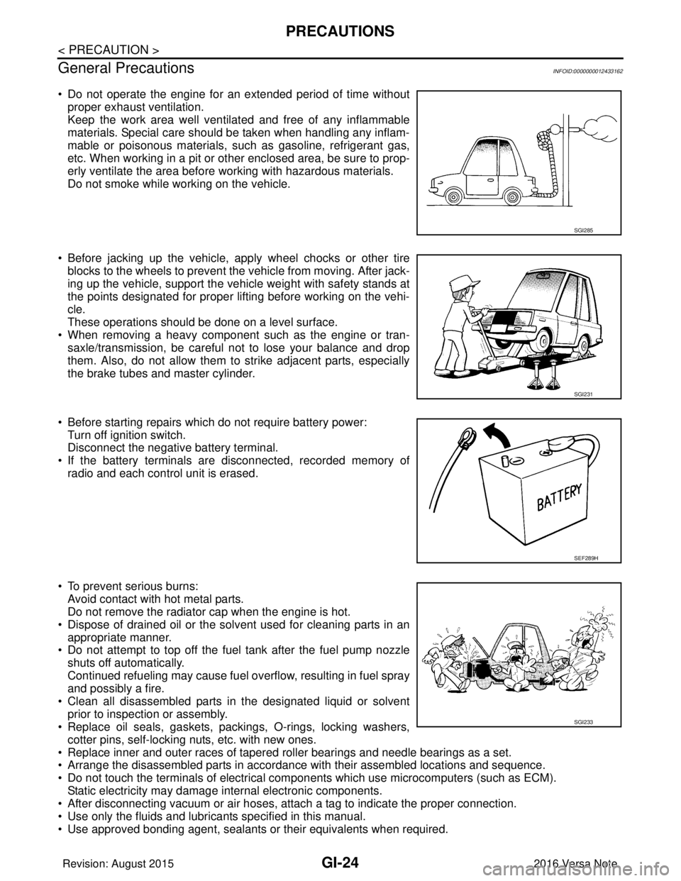
General Precautions
INFOID:0000000012433162
• Do not operate the engine for an extended period of time without proper exhaust ventilation.
Keep the work area well ventilated and free of any inflammable
materials. Special care should be taken when handling any inflam-
mable or poisonous materials, such as gasoline, refrigerant gas,
etc. When working in a pit or other enclosed area, be sure to prop-
erly ventilate the area before working with hazardous materials.
Do not smoke while working on the vehicle.
• Before jacking up the vehicle, apply wheel chocks or other tire blocks to the wheels to prevent the vehicle from moving. After jack-
ing up the vehicle, support the vehicle weight with safety stands at
the points designated for proper lifting before working on the vehi-
cle.
These operations should be done on a level surface.
• When removing a heavy component such as the engine or tran- saxle/transmission, be careful not to lose your balance and drop
them. Also, do not allow them to strike adjacent parts, especially
the brake tubes and master cylinder.
• Before starting repairs which do not require battery power: Turn off ignition switch.
Disconnect the negative battery terminal.
• If the battery terminals are disconnected, recorded memory of radio and each control unit is erased.
• To prevent serious burns: Avoid contact with hot metal parts.
Do not remove the radiator cap when the engine is hot.
• Dispose of drained oil or the solvent used for cleaning parts in an appropriate manner.
• Do not attempt to top off the fuel tank after the fuel pump nozzle
shuts off automatically.
Continued refueling may cause fuel overflow, resulting in fuel spray
and possibly a fire.
• Clean all disassembled parts in the designated liquid or solvent prior to inspection or assembly.
• Replace oil seals, gaskets, packings, O-rings, locking washers,
cotter pins, self-locking nuts, etc. with new ones.
• Replace inner and outer races of tapered roller bearings and needle bearings as a set.
• Arrange the disassembled parts in accordance with their assembled locations and sequence.
• Do not touch the terminals of electrical com ponents which use microcomputers (such as ECM).
Static electricity may damage internal electronic components.
• After disconnecting vacuum or air hoses, atta ch a tag to indicate the proper connection.
• Use only the fluids and lubricants specified in this manual.
• Use approved bonding agent, sealants or their equivalents when required.
SGI285
SGI231
SEF289H
SGI233
Revision: August 2015 2016 Versa Note
cardiagn.com
Page 1926 of 3641

GI-38
< BASIC INSPECTION >
SERVICE INFORMATION FOR ELECTRICAL INCIDENT
BASIC INSPECTION
SERVICE INFORMATION FOR ELECTRICAL INCIDENT
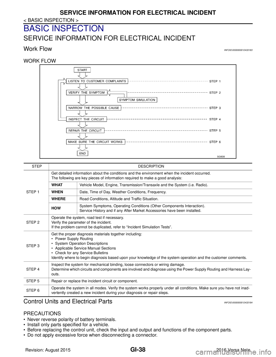
Work FlowINFOID:0000000012433183
WORK FLOW
Control Units and Electrical PartsINFOID:0000000012433184
PRECAUTIONS
• Never reverse polarity of battery terminals.
• Install only parts specified for a vehicle.
• Before replacing the control unit, check the i nput and output and functions of the component parts.
• Do not apply excessive force when disconnecting a connector.
SGI838
STEP DESCRIPTION
STEP 1 Get detailed information about the conditions and the environment when the incident occurred.
The following are key pieces of information required to make a good analysis:
WHAT
Vehicle Model, Engine, Transmission/Transaxle and the System (i.e. Radio).
WHEN Date, Time of Day, Weather Conditions, Frequency.
WHERE Road Conditions, Altitude and Traffic Situation.
HOW System Symptoms, Operating Conditions
(Other Components Interaction).
Service History and if any After Market Accessories have been installed.
STEP 2 Operate the system, road test if necessary.
Verify the parameter of the incident.
If the problem cannot be duplicated, refer to “Incident Simulation Tests”.
STEP 3 Get the proper diagnosis materials together including:
• Power Supply Routing
• System Operation Descriptions
• Applicable Service Manual Sections
• Check for any Service Bulletins
Identify where to begin diagnosis based upon your knowledge of the system operation and the customer comments.
STEP 4 Inspect the system for mechanical binding, loose connectors or wiring damage.
Determine which circuits and components are involved and diagnose using the Power Supply Routing and Harness Lay-
outs.
STEP 5 Repair or replace the incident circuit or component.
STEP 6 Operate the system in all modes. Verify the system works properly under all conditions. Make sure you have not inad-
vertently created a new incident during your diagnosis or repair steps.
Revision: August 2015
2016 Versa Note
cardiagn.com
Page 1932 of 3641

GI-44
< BASIC INSPECTION >
SERVICE INFORMATION FOR ELECTRICAL INCIDENT
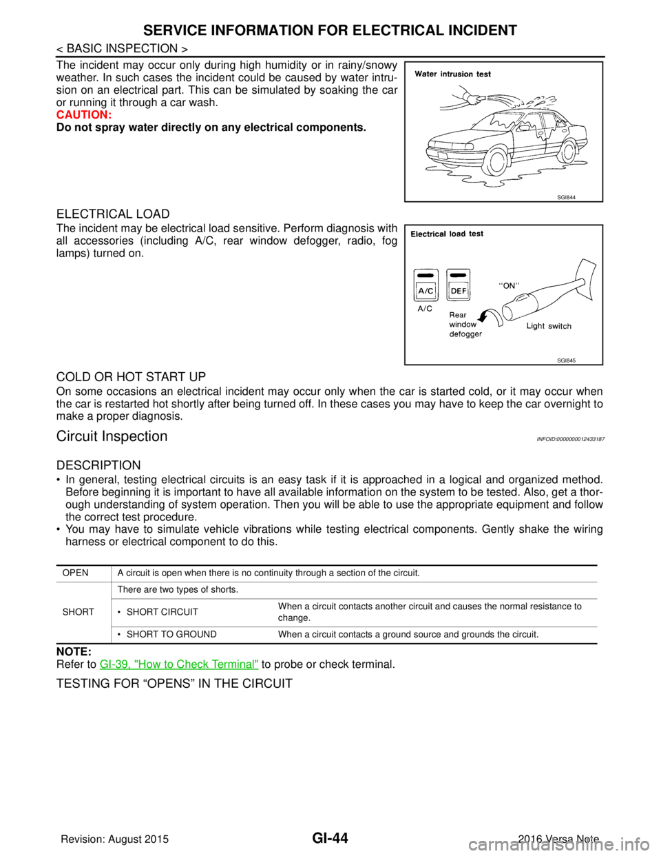
The incident may occur only during high humidity or in rainy/snowy
weather. In such cases the incident could be caused by water intru-
sion on an electrical part. This can be simulated by soaking the car
or running it through a car wash.
CAUTION:
Do not spray water directly on any electrical components.
ELECTRICAL LOAD
The incident may be electrical load sensitive. Perform diagnosis with
all accessories (including A/C, rear window defogger, radio, fog
lamps) turned on.
COLD OR HOT START UP
On some occasions an electrical incident may occur only when the car is started cold, or it may occur when
the car is restarted hot shortly after being turned off. In these cases you may have to keep the car overnight to
make a proper diagnosis.
Circuit InspectionINFOID:0000000012433187
DESCRIPTION
• In general, testing electrical circuits is an easy task if it is approached in a logical and organized method.
Before beginning it is important to have all available information on the system to be tested. Also, get a thor-
ough understanding of system operation. Then you will be able to use the appropriate equipment and follow
the correct test procedure.
• You may have to simulate vehicle vibrations while te sting electrical components. Gently shake the wiring
harness or electrical component to do this.
NOTE:
Refer to GI-39, "
How to Check Terminal" to probe or check terminal.
TESTING FOR “OPENS” IN THE CIRCUIT
SGI844
SGI845
OPEN A circuit is open when there is no continuity through a section of the circuit.
SHORT There are two types of shorts.
• SHORT CIRCUIT
When a circuit contacts another circuit and causes the normal resistance to
change.
• SHORT TO GROUND When a circuit contacts a ground source and grounds the circuit.
Revision: August 2015 2016 Versa Note
cardiagn.com
Page 2651 of 3641

PG-64
< BASIC INSPECTION >
INSPECTION AND ADJUSTMENT
INSPECTION AND ADJUSTMENT
ADDITIONAL SERVICE WHEN REMOVING BATTERY NEGATIVE TERMINAL
ADDITIONAL SERVICE WHEN REMOVING BATTERY NEGATIVE TERMINAL : Spe-
cial Repair Requirement
INFOID:0000000012433129
Required Procedure After Battery Disconnection
System ItemReference
Engine Control System Idle Air Volume Learning EC-130
Audio, Visual & Navigation SystemAudio (Radio Preset) Refer to Owner's Manual.
Navigation System
Refer to Owner's Manual.
Revision: August 2015 2016 Versa Note
cardiagn.com