2016 NISSAN NOTE coolant level
[x] Cancel search: coolant levelPage 1903 of 3641
ABBREVIATIONSGI-15
< HOW TO USE THIS MANUAL >
C
DE
F
G H
I
J
K L
M B
GI
N
O P
E
F
G
H
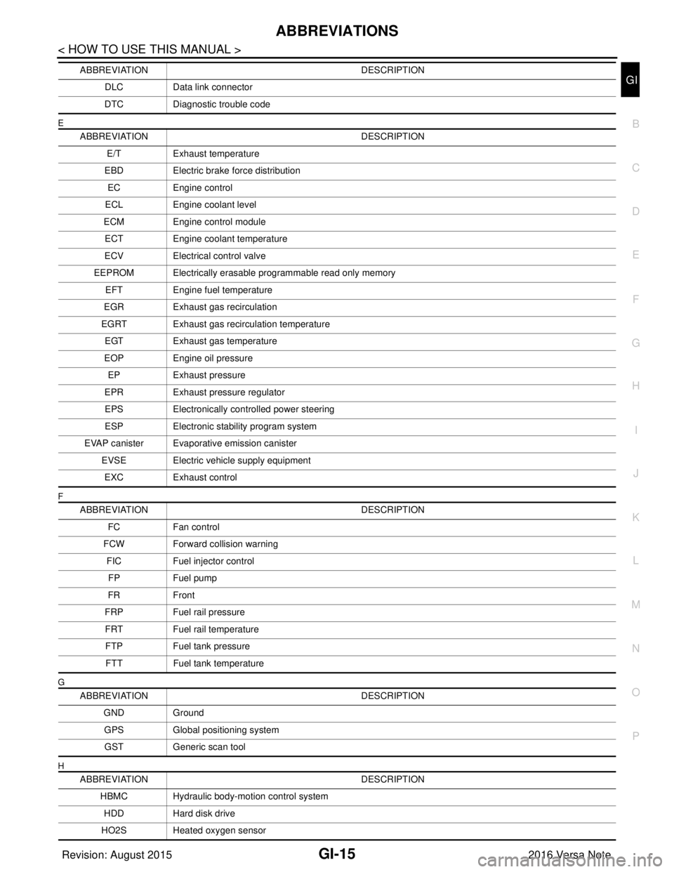
DLC Data link connector
DTC Diagnostic trouble code
ABBREVIATION DESCRIPTION
E/T Exhaust temperature
EBD Electric brake force distribution
EC Engine control
ECL Engine coolant level
ECM Engine control module
ECT Engine coolant temperature
ECV Electrical control valve
EEPROM Electrically erasable programmable read only memory EFT Engine fuel temperature
EGR Exhaust gas recirculation
EGRT Exhaust gas recirculation temperature EGT Exhaust gas temperature
EOP Engine oil pressure
EP Exhaust pressure
EPR Exhaust pressure regulator
EPS Electronically controlled power steering
ESP Electronic stability program system
EVAP canister Evaporative emission canister EVSE Electric vehicle supply equipment
EXC Exhaust control
ABBREVIATION DESCRIPTION
FC Fan control
FCW Forward collision warning
FIC Fuel injector control
FP Fuel pump
FR Front
FRP Fuel rail pressure
FRT Fuel rail temperature
FTP Fuel tank pressure
FTT Fuel tank temperature
ABBREVIATION DESCRIPTION
GND Ground
GPS Global positioning system
GST Generic scan tool
ABBREVIATION DESCRIPTION
HBMC Hydraulic body-motion control system HDD Hard disk drive
HO2S Heated oxygen sensor
ABBREVIATION
DESCRIPTION
Revision: August 2015 2016 Versa Note
cardiagn.com
Page 2017 of 3641

INSUFFICIENT HEATINGHAC-49
< SYMPTOM DIAGNOSIS > [MANUAL AIR CONDITIONING]
C
D
E
F
G H
J
K L
M A
B
HAC
N
O P
INSUFFICIENT HEATING
DescriptionINFOID:0000000012430752
Symptom
• Insufficient heating
• No warm air comes out. (Air flow volume is normal.)
Diagnosis ProcedureINFOID:0000000012430753
NOTE:
Perform self-diagnosis with CONSULT before performing sy mptom diagnosis. If any malfunction result or DTC
is detected, perform the corresponding diagnosis.
1.CHECK COOLING SYSTEM
1. Check engine coolant level and check for leakage. Refer to CO-8, "
Inspection".
2. Check radiator cap. Refer to CO-12, "
RADIATOR CAP : Inspection".
3. Check water flow sounds of the engine coolant. Refer to CO-9, "
Refilling".
Is the inspection result normal?
YES >> GO TO 2.
NO >> Refill engine coolant and repair or replace the parts depending on the inspection results.
2.CHECK HEATER HOSE
Check installation of heater hose by visually or touching.
Is the inspection result normal?
YES >> GO TO 3.
NO >> Repair or replace parts depending on the inspection results.
3.CHECK HEATER CORE
1. Check temperature of inlet hose and outlet hose of heater core.
2. Check that inlet side of heater core is hot and the outle t side is slightly lower than/almost equal to the inlet
side.
CAUTION:
Always perform the temperature inspection in a sh ort period of time because the engine coolant
temperature is very hot.
Is the inspection result normal?
YES >> GO TO 4.
NO >> Replace heater core. Refer to HA-35, "
HEATER CORE : Removal and Installation".
4.CHECK AIR LEAKAGE FROM EACH DUCT
Check duct and nozzle, etc. of air conditioning system for air leakage.
Is the inspection result normal?
YES >> Check air mix door cable inst allation and air mix door operation.
NO >> Repair or replace parts depending on the inspection results.
Revision: August 2015 2016 Versa Note
cardiagn.com
Page 2321 of 3641
MA-6
< PERIODIC MAINTENANCE >
GENERAL MAINTENANCE
UNDER THE HOOD AND VEHICLE
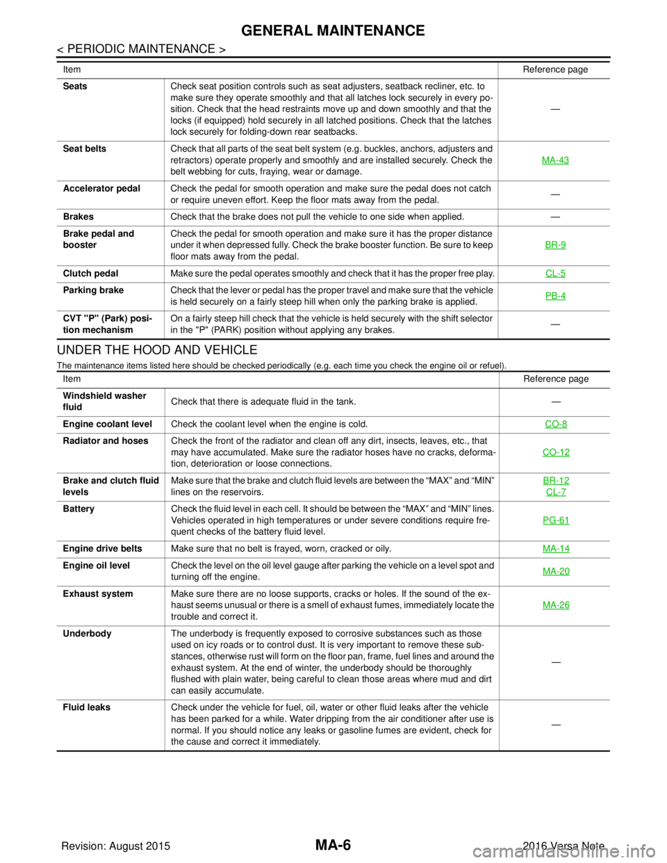
The maintenance items listed here should be checked periodically (e.g. each time you check the engine oil or refuel).
SeatsCheck seat position controls such as seat adjusters, seatback recliner, etc. to
make sure they operate smoothly and that all latches lock securely in every po-
sition. Check that the head restraints move up and down smoothly and that the
locks (if equipped) hold securely in all latched positions. Check that the latches
lock securely for folding-down rear seatbacks. —
Seat belts Check that all parts of the seat belt system (e.g. buckles, anchors, adjusters and
retractors) operate properly and smoothly and are installed securely. Check the
belt webbing for cuts, fraying, wear or damage. MA-43
Accelerator pedal
Check the pedal for smooth operation and make sure the pedal does not catch
or require uneven effort. Keep the floor mats away from the pedal. —
Brakes Check that the brake does not pull the vehicle to one side when applied. —
Brake pedal and
booster Check the pedal for smooth operation and make sure it has the proper distance
under it when depressed fully. Check the brake booster function. Be sure to keep
floor mats away from the pedal. BR-9
Clutch pedal
Make sure the pedal operates smoothly and check that it has the proper free play. CL-5
Parking brakeCheck that the lever or pedal has the proper travel and make sure that the vehicle
is held securely on a fairly steep hill when only the parking brake is applied. PB-4
CVT "P" (Park) posi-
tion mechanismOn a fairly steep hill check that the vehicle is held securely with the shift selector
in the "P" (PARK) position without applying any brakes.
—
Item
Reference page
Item Reference page
Windshield washer
fluid Check that there is adequate fluid in the tank.
—
Engine coolant level Check the coolant level when the engine is cold. CO-8
Radiator and hosesCheck the front of the radiator and clean off any dirt, insects, leaves, etc., that
may have accumulated. Make sure the radiator hoses have no cracks, deforma-
tion, deterioration or loose connections. CO-12
Brake and clutch fluid
levelsMake sure that the brake and clutch fluid levels are between the “MAX” and “MIN”
lines on the reservoirs. BR-12
CL-7
Battery
Check the fluid level in each cell. It should be between the “MAX” and “MIN” lines.
Vehicles operated in high temperatures or under severe conditions require fre-
quent checks of the battery fluid level. PG-61
Engine drive belts
Make sure that no belt is frayed, worn, cracked or oily. MA-14
Engine oil levelCheck the level on the oil level gauge after parking the vehicle on a level spot and
turning off the engine. MA-20
Exhaust system
Make sure there are no loose supports, cracks or holes. If the sound of the ex-
haust seems unusual or there is a smell of exhaust fumes, immediately locate the
trouble and correct it. MA-26
Underbody
The underbody is frequently exposed to corrosive substances such as those
used on icy roads or to control dust. It is very important to remove these sub-
stances, otherwise rust will form on the floor pan, frame, fuel lines and around the
exhaust system. At the end of winter, the underbody should be thoroughly
flushed with plain water, being careful to clean those areas where mud and dirt
can easily accumulate. —
Fluid leaks Check under the vehicle for fuel, oil, water or other fluid leaks after the vehicle
has been parked for a while. Water dripping from the air conditioner after use is
normal. If you should notice any leaks or gasoline fumes are evident, check for
the cause and correct it immediately. —
Revision: August 2015
2016 Versa Note
cardiagn.com
Page 2326 of 3641
RECOMMENDED FLUIDS AND LUBRICANTSMA-11
< PERIODIC MAINTENANCE >
C
DE
F
G H
I
J
K L
M B
MA
N
O A
RECOMMENDED FLUIDS AND LUBRICANTS
Fluids and LubricantsINFOID:0000000012432245
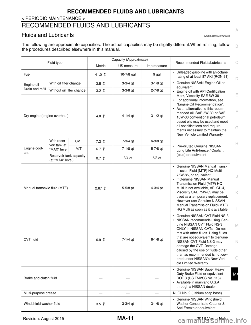
The following are approximate capacities. The actual capa
cities may be slightly different.When refilling, follow
the procedures described elsewhere in this manual.
Fluid type Capacity (Approximate)
Recommended Fluids/Lubricants
Metric US measure Imp measure
Fuel 41.0 10-7/8 gal
9 gal• Unleaded gasoline with an octane
rating of at least 87 AKI (RON 91)
Engine oil
Drain and refill With oil filter change
3.5 3-3/4 qt 3-1/8 qt
• Genuine NISSAN Engine Oil or
equivalent
• Engine oil with API Certification
Mark, Viscosity SAE 5W-30
• For additional information, see "Engine Oil Recommendation".
• As an alternative to this recom-
mended oil, SAE 5W-30 or SAE
10W-30 conventional petroleum
based oils may be used and meet
all specifications and require-
ments necessary to maintain the
New Vehicle Limited Warranty.
Without oil filter change
3.2 3-3/8 qt 2-7/8 qt
Dry engine (engine overhaul) 4.0 4-1/4 qt 3-1/2 qt
Engine cool-
ant With reser-
voir tank at
“MAX” level
CVT
7.3 7-3/4 qt 6-3/8 qt
• Pre-diluted Genuine NISSAN Long Life Anti-freeze / Coolant
(blue) or equivalent
M/T
6.7 7-1/8 qt 5-7/8 qt
Reservoir tank capacity
(at “MAX” level) 0.7
3/4 qt
5/8 qt
Manual transaxle fluid (MTF) 2.67 5-5/8 pt 4-3/4 pt • Genuine NISSAN
Manual Trans-
mission Fluid (MTF) HQ Multi
75W-85, or equivalent
• If Genuine NISSAN Manual
Transmission Fluid (MTF) HQ
Multi is not available, API GL-4,
Viscosity SAE 75W-85 may be
used as a temporary replacement.
However use Genuine NISSAN
Manual Transmission Fluid (MTF)
HQ Multi as soon as it is available.
CVT fluid 6.9 7-1/4 qt 6-1/8 qt • Genuine NISSAN CVT Fluid NS-3
• NISSAN recommends using Gen-
uine NISSAN CVT Fluid NS-3
ONLY in NISSAN CVTs. Do not
mix with other fluids. Using fluids
that are not equivalent to Genuine
NISSAN CVT Fluid NS-3 may
damage the CVT. Damage
caused by the use of fluids other
than as recommended is not cov-
ered under NISSAN's New Vehi-
cle Limited Warranty.
Brake and clutch fluid —— —• Genuine NISSAN Super Heavy
Duty Brake Fluid or equivalent
DOT 3 (US FMVSS No. 116)
• Available in mainland U.S.A.
through a NISSAN dealer.
Multi-purpose grease —— — NLGI No. 2 (Lithium soap base)
Windshield washer fluid 3.5 3-3/4 qt 3-1/8 qt • Genuine NISSAN Windshield
Washer Concentrate Cleaner &
Anti-Freeze or equivalent
Revision: August 2015 2016 Versa Note
cardiagn.com
Page 2330 of 3641
ENGINE MAINTENANCEMA-15
< PERIODIC MAINTENANCE >
C
DE
F
G H
I
J
K L
M B
MA
N
O A
• When checking immediately after in
stallation, first adjust it to the specified value. Then, after
turning crankshaft two turns or more, readjust to the specified value to avoid variation in deflec-
tion between pulleys.
• When the tension adjustment is performed, the lo ck nut should be in the condition at Step 2. If
the tension adjustment is perfo rmed when the lock nut is loosened more than the temporary
tightening, the idler pulley tilts and the co rrect tension adjustment cannot be performed.
4. Tighten the lock nut to final tightening specification.
ENGINE COOLANT
ENGINE COOLANT : InspectionINFOID:0000000012432252
CHECKING COOLING SYSTEM HOSES
Check hoses for the following:
• Improper attachment
• Leaks
•Cracks
• Damage
• Loose connections
• Chafing
• Deterioration
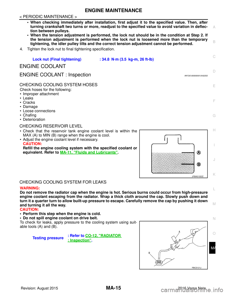
CHECKING RESERVOIR LEVEL
• Check that the reservoir tank engine coolant level is within the MAX (A) to MIN (B) range when the engine is cool.
• Adjust the engine coolant level if necessary. CAUTION:
Refill the engine cooling system with the specified coolant or
equivalent. Refer to MA-11, "
Fluids and Lubricants".
CHECKING COOLING SYSTEM FOR LEAKS
WARNING:
Do not remove the radiator cap when the engine is hot. Serious burns could occur from high-pressure
engine coolant escaping from the radiator. Wrap a thick cloth around the cap. Slowly push down and
turn it a quarter turn to allow built-up pressure to escape. Carefully remove the cap by pushing it down
and turning it all the way.
CAUTION:
• Perform this step when the engine is cold.
• Do not spill engine coolant on drive belt.
To check for leaks, apply pressure to the cooling system using suit-
able tools (A) and (B). Lock nut (Final tightening) :
34.8 N·m (3.5 kg-m, 26 ft-lb)
JPBIA0102ZZ
Testing pressure: Refer to CO-12, "RADIATOR
: Inspection".
PBIC5121J
Revision: August 2015
2016 Versa Note
cardiagn.com
Page 2332 of 3641
ENGINE MAINTENANCEMA-17
< PERIODIC MAINTENANCE >
C
DE
F
G H
I
J
K L
M B
MA
N
O A
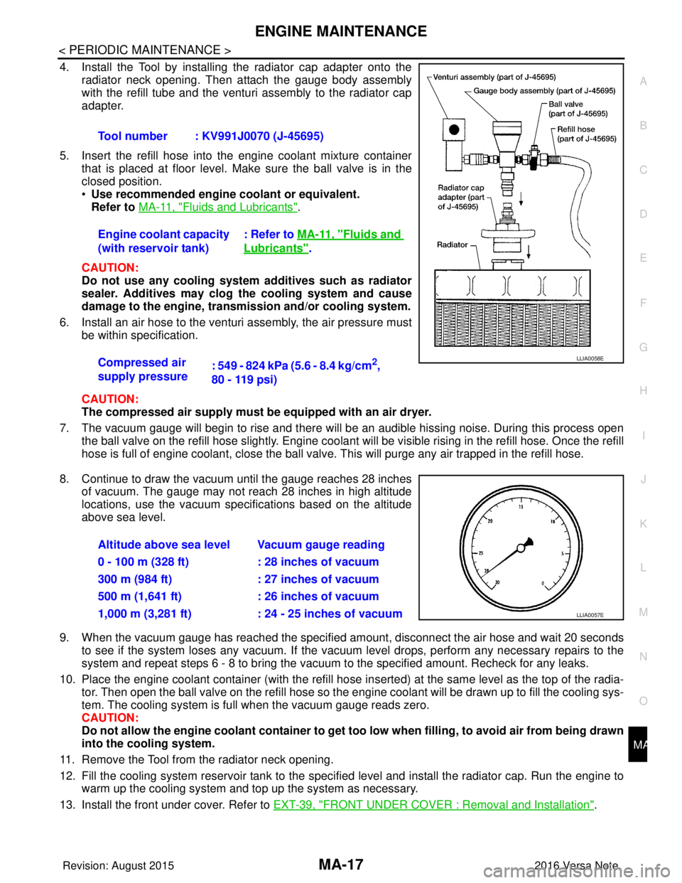
4. Install the Tool by installing the radiator cap adapter onto the
radiator neck opening. Then attach the gauge body assembly
with the refill tube and the venturi assembly to the radiator cap
adapter.
5. Insert the refill hose into the engine coolant mixture container that is placed at floor level. Make sure the ball valve is in the
closed position.
•Use recommended engine coolant or equivalent.
Refer to MA-11, "
Fluids and Lubricants".
CAUTION:
Do not use any cooling system additives such as radiator
sealer. Additives may clog the cooling system and cause
damage to the engine, transmission and/or cooling system.
6. Install an air hose to the venturi assembly, the air pressure must be within specification.
CAUTION:
The compressed air supply must be equipped with an air dryer.
7. The vacuum gauge will begin to rise and there will be an audible hissing noise. During this process open the ball valve on the refill hose slightly. Engine coolant will be visible rising in the refill hose. Once the refill
hose is full of engine coolant, close the ball valve. This will purge any air trapped in the refill hose.
8. Continue to draw the vacuum until the gauge reaches 28 inches of vacuum. The gauge may not reach 28 inches in high altitude
locations, use the vacuum specifications based on the altitude
above sea level.
9. When the vacuum gauge has reached the specified amount, disconnect the air hose and wait 20 seconds
to see if the system loses any vacuum. If the vacuum level drops, perform any necessary repairs to the
system and repeat steps 6 - 8 to br ing the vacuum to the specified amount. Recheck for any leaks.
10. Place the engine coolant container (with the refill hose in serted) at the same level as the top of the radia-
tor. Then open the ball valve on the refill hose so the engine coolant will be drawn up to fill the cooling sys-
tem. The cooling system is full when the vacuum gauge reads zero.
CAUTION:
Do not allow the engine coolant co ntainer to get too low when filling, to avoid air from being drawn
into the cooling system.
11. Remove the Tool from the radiator neck opening.
12. Fill the cooling system reservoir tank to the specif ied level and install the radiator cap. Run the engine to
warm up the cooling system and top up the system as necessary.
13. Install the front under cover. Refer to EXT-39, "
FRONT UNDER COVER : Removal and Installation".
Tool number : KV991J0070 (J-45695)
Engine coolant capacity
(with reservoir tank)
: Refer to
MA-11, "
Fluids and
Lubricants".
Compressed air
supply pressure : 549 - 824 kPa (5.6 - 8.4 kg/cm
2,
80 - 119 psi)LLIA0058E
Altitude above sea level Vacuum gauge reading
0 - 100 m (328 ft) : 28 inches of vacuum
300 m (984 ft) : 27 inches of vacuum
500 m (1,641 ft) : 26 inches of vacuum
1,000 m (3,281 ft) : 24 - 25 inches of vacuum
LLIA0057E
Revision: August 2015 2016 Versa Note
cardiagn.com
Page 2335 of 3641
MA-20
< PERIODIC MAINTENANCE >
ENGINE MAINTENANCE
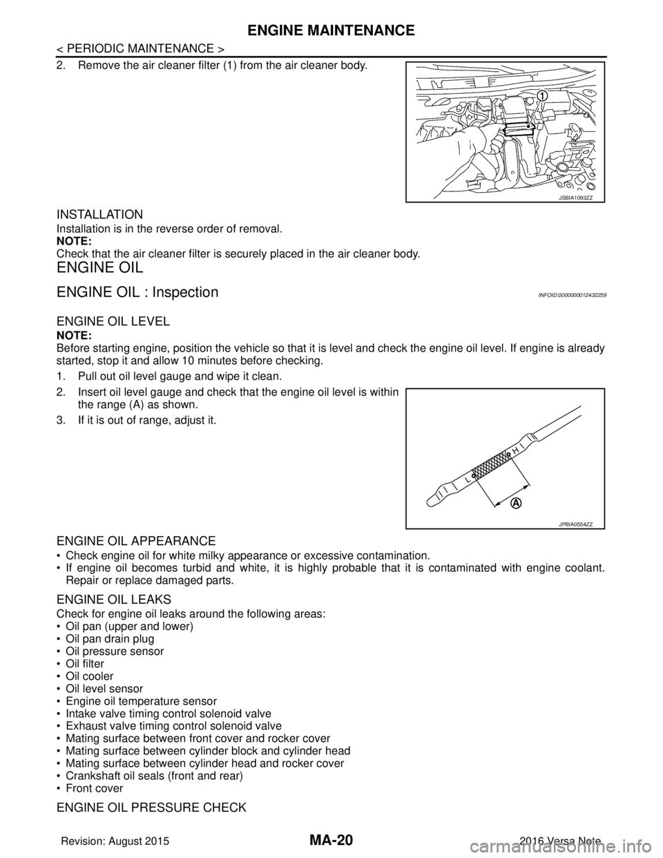
2. Remove the air cleaner filter (1) from the air cleaner body.
INSTALLATION
Installation is in the reverse order of removal.
NOTE:
Check that the air cleaner filter is securely placed in the air cleaner body.
ENGINE OIL
ENGINE OIL : InspectionINFOID:0000000012432259
ENGINE OIL LEVEL
NOTE:
Before starting engine, position the vehicle so that it is level and check the engine oil level. If engine is already
started, stop it and allow 10 minutes before checking.
1. Pull out oil level gauge and wipe it clean.
2. Insert oil level gauge and check that the engine oil level is withinthe range (A) as shown.
3. If it is out of range, adjust it.
ENGINE OIL APPEARANCE
• Check engine oil for white milky appearance or excessive contamination.
• If engine oil becomes turbid and white, it is highl y probable that it is contaminated with engine coolant.
Repair or replace damaged parts.
ENGINE OIL LEAKS
Check for engine oil leaks around the following areas:
• Oil pan (upper and lower)
• Oil pan drain plug
• Oil pressure sensor
• Oil filter
• Oil cooler
• Oil level sensor
• Engine oil temperature sensor
• Intake valve timing control solenoid valve
• Exhaust valve timing control solenoid valve
• Mating surface between front cover and rocker cover
• Mating surface between cylinder block and cylinder head
• Mating surface between cylinder head and rocker cover
• Crankshaft oil seals (front and rear)
• Front cover
ENGINE OIL PRESSURE CHECK
JSBIA1093ZZ
JPBIA0554ZZ
Revision: August 2015 2016 Versa Note
cardiagn.com
Page 2367 of 3641

MWI
COMPONENT PARTSMWI-9
< SYSTEM DESCRIPTION > [TYPE A]
C
D
E
F
G H
I
J
K L
M B A
O P
METER SYSTEM : Combination MeterINFOID:0000000012432542
The combination meter controls the following items a ccording to the signals received from each unit via CAN
communication and the signals from switches and sensors:
• Measuring instruments
• Indicator lamps
• Warning lamps
• Meter illumination control
• Information display
ARRANGEMENT OF COMBINATION METER
6. ECM Transmits the following signals to the combination meter via CAN communication:
• Engine speed signal
• Engine coolant temperature signal
• Fuel consumption monitor signal
• Engine oil pressure sensor signal
Refer to EC-14, "
ENGINE CONTROL SYSTEM : ComponentPartsLocation" for de-
tailed installation location.
7. BCM Transmits the following signals to the combination meter via CAN communication:
• Door switch signal
• Buzzer signal
Refer to BCS-137, "
Removal and Installation" for detailed installation location.
8. Combination meter Refer to MWI-9, "
METER SYSTEM : Combination Meter".
9. Fuel level sensor unit and fuel pump
(fuel level sensor) Transmits the fuel level sensor signal to the combination meter.
No.
Component Function
U: USAEU: Except USA
AWNIA3633ZZ
Revision: August 2015 2016 Versa Note
cardiagn.com