2016 NISSAN NOTE contents
[x] Cancel search: contentsPage 1946 of 3641
GW-6
< SYMPTOM DIAGNOSIS >
SQUEAK AND RATTLE TROUBLE DIAGNOSES
If possible, drive the vehicle with the customer until the noise is duplicated. Note any additional information on
the Diagnostic Worksheet regarding the conditions or lo cation of the noise. This information can be used to
duplicate the same conditions when you confirm the repair.
If the noise can be duplicated easily during the test drive, to help identify the source of the noise, try to dupli-
cate the noise with the vehicle stopped by doing one or all of the following:
1) Close a door.
2) Tap or push/pull around the area where the noise appears to be coming from.
3) Rev the engine.
4) Use a floor jack to recreate vehicle “twist”.
5) At idle, apply engine load (electrical load, half-clutch on M/T model, drive position on CVT and A/T models).
6) Raise the vehicle on a hoist and hit a tire with a rubber hammer.
• Drive the vehicle and attempt to duplicate the conditions the customer states exist when the noise occurs.
• If it is difficult to duplicate the noise, drive the v ehicle slowly on an undulating or rough road to stress the
vehicle body.
CHECK RELATED SERVICE BULLETINS
After verifying the customer concern or symptom, chec k ASIST for Technical Service Bulletins (TSBs) related
to that concern or symptom.
If a TSB relates to the symptom, follo w the procedure to repair the noise.
LOCATE THE NOISE AND IDENTIFY THE ROOT CAUSE
1. Narrow down the noise to a general area. To help pi npoint the source of the noise, use a listening tool
(Chassis Ear: J-39570, Engine Ear: J-39565 and mechanic's stethoscope).
2. Narrow down the noise to a more specific area and identify the cause of the noise by: • removing the components in the area that you suspect the noise is coming from.Do not use too much force when removing clips and fasteners, otherwise clips and fasteners can be
broken or lost during the repair, resulting in the creation of new noise.
• tapping or pushing/pulling the component that you suspect is causing the noise. Do not tap or push/pull the component with excessive force, otherwise the noise will be eliminated only
temporarily.
• feeling for a vibration with your hand by touching the component(s) that you suspec t is (are) causing the
noise.
• placing a piece of paper between components that you suspect are causing the noise.
• looking for loose components and contact marks.
Refer to GW-6, "
Generic Squeak and Rattle Troubleshooting".
REPAIR THE CAUSE
• If the cause is a loose component, tighten the component securely.
• If the cause is insufficient clearance between components:
- separate components by repositioning or loos ening and retightening the component, if possible.
- insulate components with a suitable insulator such as urethane pads, foam blocks, felt cloth tape or urethane tape. A NISSAN Squeak and Rattle Kit (J-50397) is av ailable through your authorized NISSAN Parts Depart-
ment.
CAUTION:
Do not use excessive force as many components are constructed of plastic and may be damaged.
NOTE:
• Always check with the Parts Department for the latest parts information.
• The materials contained in the NISSAN Squeak and Rattle Kit (J-50397) are listed on the inside cover of the
kit; and can each be ordered separately as needed.
• The following materials not found in the kit can also be used to repair squeaks and rattles.
- SILICONE GREASE: Use instead of UHMW tape that will be visible or does not fit. The silicone grease will only last a few months.
- SILICONE SPRAY: Use when grease cannot be applied.
- DUCT TAPE: Use to eliminate movement.
CONFIRM THE REPAIR
Confirm that the cause of a noise is repaired by test driving the vehicle. Operate the vehicle under the same
conditions as when the noise originally occurred. Refer to the notes on the Diagnostic Worksheet.
Generic Squeak and Rattle TroubleshootingINFOID:0000000012430528
Refer to Table of Contents for specific component removal and installation information.
Revision: August 2015 2016 Versa Note
cardiagn.com
Page 1969 of 3641
HAC-1
VENTILATION, HEATER & AIR CONDITIONER
C
DE
F
G H
J
K L
M
SECTION HAC
A
B
HAC
N
O P
CONTENTS
HEATER & AIR CONDITIONING CONTROL SYSTEM
MANUAL AIR CONDITIONING
PRECAUTION ....... ........................................
3
PRECAUTIONS .............................................. .....3
Precaution for Supplemental Restraint System
(SRS) "AIR BAG" and "SEAT BELT PRE-TEN-
SIONER" ............................................................. ......
3
Precaution for Procedure without Cowl Top Cover ......3
Precaution for Work ..................................................3
Precautions For Refrigerant System Service ............4
Service Equipment .............................................. ......6
PREPARATION ............................................8
PREPARATION .............................................. .....8
Special Service Tool ........................................... ......8
Commercial Service Tool ..........................................8
SYSTEM DESCRIPTION ..............................9
COMPONENT PARTS ................................... .....9
Component Parts Location .................................. ......9
SYSTEM .............................................................11
System Description ............................................. ....11
Compressor Control ................................................11
Door Control ............................................................13
OPERATION .......................................................16
Switch Name and Function ................................. ....16
DIAGNOSIS SYSTEM (BCM) (WITH INTELLI-
GENT KEY SYSTEM) .........................................
17
COMMON ITEM ..................................................... ....17
COMMON ITEM : CONSULT Function (BCM -
COMMON ITEM) .....................................................
17
AIR CONDITIONER ............................................... ....18
AIR CONDITIONER : CONSULT Function (BCM -
AIR CONDITIONER) ........................................... ....
18
DIAGNOSIS SYSTEM (BCM) (WITHOUT IN-
TELLIGENT KEY SYSTEM) .............................
19
COMMON ITEM ..................................................... ....19
COMMON ITEM : CONSULT Function (BCM -
COMMON ITEM) .....................................................
19
AIR CONDITIONER ............................................... ....20
AIR CONDITIONER : CONSULT Function (BCM -
AIR CONDITIONER) ........................................... ....
20
ECU DIAGNOSIS INFORMATION ..............21
BCM, ECM, IPDM E/R .......................................21
List of ECU Reference ......................................... ....21
WIRING DIAGRAM ......................................22
MANUAL AIR CONDITIONING SYSTEM .........22
Wiring Diagram .................................................... ....22
BASIC INSPECTION ...................................28
DIAGNOSIS AND REPAIR WORKFLOW ........28
Workflow .............................................................. ....28
OPERATION INSPECTION ..............................30
Work Procedure .......................................................30
DTC/CIRCUIT DIAGNOSIS .........................32
A/C ON SIGNAL ................................................32
Component Function Check ................................ ....32
Diagnosis Procedure ...............................................32
Component Inspection .............................................34
BLOWER FAN ON SIGNAL .............................35
Component Function Check ....................................35
Diagnosis Procedure ...............................................35
DEFROSTER POSITION SIGNAL ....................37
Description ...............................................................37
Component Function Check ....................................37
Revision: August 2015 2016 Versa Note
cardiagn.com
Page 2026 of 3641
HA-1
VENTILATION, HEATER & AIR CONDITIONER
C
DE
F
G H
J
K L
M
SECTION HA
A
B
HA
N
O P
CONTENTS
HEATER & AIR CONDITIONING SYSTEM
PRECAUTION ....... ........................................3
PRECAUTIONS .............................................. .....3
Precaution for Supplemental Restraint System
(SRS) "AIR BAG" and "SEAT BELT PRE-TEN-
SIONER" ............................................................. ......
3
Precaution for Work ..................................................3
Precaution for Procedure without Cowl Top Cover ......4
Precautions For Refrigerant System Service ............4
Service Equipment .............................................. ......6
PREPARATION ............................................9
PREPARATION .............................................. .....9
Special Service Tool ........................................... ......9
Commercial Service Tool ..........................................9
Sealant and/or Oil ...................................................11
SYSTEM DESCRIPTION .............................12
COMPONENT PARTS ................................... ....12
Component Parts Location .................................. ....12
BASIC INSPECTION ...................................13
DIAGNOSIS AND REPAIR WORKFLOW ..... ....13
Workflow ............................................................. ....13
SYMPTOM DIAGNOSIS ..............................15
REFRIGERATION SYSTEM SYMPTOMS ..... ....15
Trouble Diagnosis For Unusual Pressure ........... ....15
Symptom Table .......................................................15
NOISE .................................................................17
Symptom Table ................................................... ....17
PERIODIC MAINTENANCE .........................18
REFRIGERANT .............................................. ....18
Description .......................................................... ....18
Leak Test ................................................................18
Recycle Refrigerant .................................................20
Charge Refrigerant .............................................. ....20
OIL .....................................................................22
Description ...............................................................22
Inspection ................................................................22
Perform Oil Return Operation ..................................22
Oil Adjusting Procedure for Components Replace-
ment Except Compressor .................................... ....
22
Oil Adjusting Procedure for Compressor Replace-
ment .........................................................................
23
PERFORMANCE TEST ....................................24
Inspection ................................................................24
REMOVAL AND INSTALLATION ...............26
COMPRESSOR .................................................26
Exploded View ..................................................... ....26
Removal and Installation .........................................26
Inspection ................................................................27
COOLER PIPE AND HOSE ..............................28
Exploded View .........................................................28
LOW-PRESSURE FLEXIBLE HOSE ..................... ....28
LOW-PRESSURE FLEXIBLE HOSE : Removal
and Installation ........................................................
28
HIGH-PRESSURE FLEXIBLE HOSE ........................29
HIGH-PRESSURE FLEXIBLE HOSE : Removal
and Installation .................................................... ....
29
HIGH-PRESSURE PIPE ............................................29
HIGH-PRESSURE PIPE : Removal and Installa-
tion ....................................................................... ....
29
CONDENSER ....................................................31
Exploded View .........................................................31
CONDENSER ......................................................... ....31
CONDENSER : Removal and Installation ...............31
LIQUID TANK ........................................................ ....32
Revision: August 2015 2016 Versa Note
cardiagn.com
Page 2063 of 3641
HRN-1
DRIVER CONTROLS
C
DE
F
G H
I
J
K
M
SECTION HRN
A
B
HRN
N
O P
CONTENTS
HORN
PRECAUTION ....... ........................................2
PRECAUTIONS .............................................. .....2
Precaution for Supplemental Restraint System
(SRS) "AIR BAG" and "SEAT BELT PRE-TEN-
SIONER" ............................................................. ......
2
WIRING DIAGRAM .......................................3
HORN .................................................................3
Wiring Diagram .................................................... .....3
REMOVAL AND INSTALLATION ................6
HORN .................................................................6
Exploded View ..................................................... .....6
Removal and Installation ..........................................6
Revision: August 2015 2016 Versa Note
cardiagn.com
Page 2069 of 3641
IP-1
BODY INTERIOR
C
DE
F
G H
I
K L
M
SECTION IP
A
B
IP
N
O P
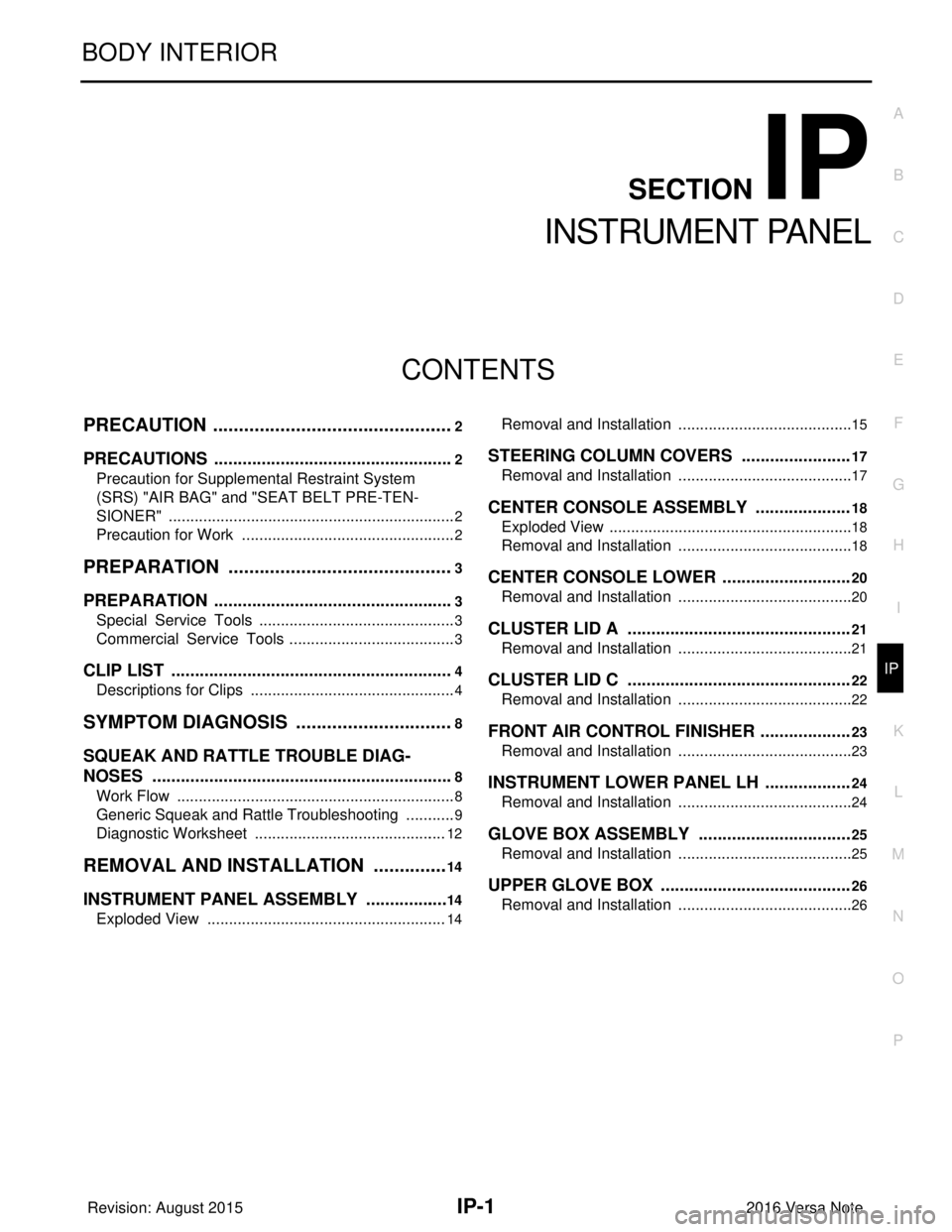
CONTENTS
INSTRUMENT PANEL
PRECAUTION ....... ........................................2
PRECAUTIONS .............................................. .....2
Precaution for Supplemental Restraint System
(SRS) "AIR BAG" and "SEAT BELT PRE-TEN-
SIONER" ............................................................. ......
2
Precaution for Work ..................................................2
PREPARATION ............................................3
PREPARATION .............................................. .....3
Special Service Tools ........................................ ......3
Commercial Service Tools .......................................3
CLIP LIST ............................................................4
Descriptions for Clips ................................................4
SYMPTOM DIAGNOSIS ...............................8
SQUEAK AND RATTLE TROUBLE DIAG-
NOSES ........................ ........................................
8
Work Flow ........................................................... ......8
Generic Squeak and Rattle Troubleshooting ............9
Diagnostic Worksheet .............................................12
REMOVAL AND INSTALLATION ...............14
INSTRUMENT PANEL ASSEMBLY .............. ....14
Exploded View .................................................... ....14
Removal and Installation ..................................... ....15
STEERING COLUMN COVERS .......................17
Removal and Installation .........................................17
CENTER CONSOLE ASSEMBLY ....................18
Exploded View .........................................................18
Removal and Installation .........................................18
CENTER CONSOLE LOWER ...........................20
Removal and Installation .........................................20
CLUSTER LID A ...............................................21
Removal and Installation .........................................21
CLUSTER LID C ...............................................22
Removal and Installation .........................................22
FRONT AIR CONTROL FINISHER ...................23
Removal and Installation .........................................23
INSTRUMENT LOWER PANEL LH ..................24
Removal and Installation .........................................24
GLOVE BOX ASSEMBLY ................................25
Removal and Installation .........................................25
UPPER GLOVE BOX ........................................26
Removal and Installation ..................................... ....26
Revision: August 2015 2016 Versa Note
cardiagn.com
Page 2077 of 3641
SQUEAK AND RATTLE TROUBLE DIAGNOSESIP-9
< SYMPTOM DIAGNOSIS >
C
DE
F
G H
I
K L
M A
B
IP
N
O P
If possible, drive the vehicle with the customer until the noise is duplicated. Note any additional information on
the Diagnostic Worksheet regarding the conditions or lo cation of the noise. This information can be used to
duplicate the same conditions when you confirm the repair.
If the noise can be duplicated easily during the test drive, to help identify the source of the noise, try to dupli-
cate the noise with the vehicle stopped by doing one or all of the following:
1) Close a door.
2) Tap or push/pull around the area where the noise appears to be coming from.
3) Rev the engine.
4) Use a floor jack to recreate vehicle “twist”.
5) At idle, apply engine load (electrical load, half-clutch on M/T model, drive position on CVT and A/T models).
6) Raise the vehicle on a hoist and hit a tire with a rubber hammer.
• Drive the vehicle and attempt to duplicate the conditions the customer states exist when the noise occurs.
• If it is difficult to duplicate the noise, drive the vehicle slowly on an undulating or rough road to stress the
vehicle body.
CHECK RELATED SERVICE BULLETINS
After verifying the customer concern or symptom, check ASIST for Technical Service Bulletins (TSBs) related
to that concern or symptom.
If a TSB relates to the symptom, follow the procedure to repair the noise.
LOCATE THE NOISE AND IDENTIFY THE ROOT CAUSE
1. Narrow down the noise to a general area. To help pinpoint the source of the noise, use a listening tool (Chassis Ear: J-39570, Engine Ear: J-39565 and mechanic's stethoscope).
2. Narrow down the noise to a more specific area and identify the cause of the noise by: • removing the components in the area that you suspect the noise is coming from.Do not use too much force when removing clips and fasteners, otherwise clips and fasteners can be
broken or lost during the repair, resulting in the creation of new noise.
• tapping or pushing/pulling the component that you suspect is causing the noise.
Do not tap or push/pull the component with excessive force, otherwise the noise will be eliminated only
temporarily.
• feeling for a vibration with your hand by touching the component(s) that you suspect is (are) causing the
noise.
• placing a piece of paper between components that you suspect are causing the noise.
• looking for loose components and contact marks. Refer to IP-9, "
Generic Squeak and Rattle Troubleshooting".
REPAIR THE CAUSE
• If the cause is a loose component, tighten the component securely.
• If the cause is insufficient clearance between components:
- separate components by repositioning or loos ening and retightening the component, if possible.
- insulate components with a suitable insulator such as urethane pads, foam blocks, felt cloth tape or urethane tape. A NISSAN Squeak and Rattle Kit (J-50397) is available through your authorized NISSAN Parts Depart-
ment.
CAUTION:
Do not use excessive force as many components are constructed of plastic and may be damaged.
NOTE:
• Always check with the Parts Department for the latest parts information.
• The materials contained in the NISSAN Squeak and Rattle Kit (J-50397) are listed on the inside cover of the
kit; and can each be ordered separately as needed.
• The following materials not found in the kit can also be used to repair squeaks and rattles.
- SILICONE GREASE: Use instead of UHMW tape that will be visible or does not fit. The silicone grease will
only last a few months.
- SILICONE SPRAY: Use when grease cannot be applied.
- DUCT TAPE: Use to eliminate movement.
CONFIRM THE REPAIR
Confirm that the cause of a noise is repaired by test driving the vehicle. Operate the vehicle under the same
conditions as when the noise originally occurred. Refer to the notes on the Diagnostic Worksheet.
Generic Squeak and Rattle TroubleshootingINFOID:0000000012430775
Refer to Table of Contents for specific component removal and installation information.
Revision: August 2015 2016 Versa Note
cardiagn.com
Page 2095 of 3641
INL-1
DRIVER CONTROLS
C
DE
F
G H
I
J
K
M
SECTION INL
A
B
INL
N
O P
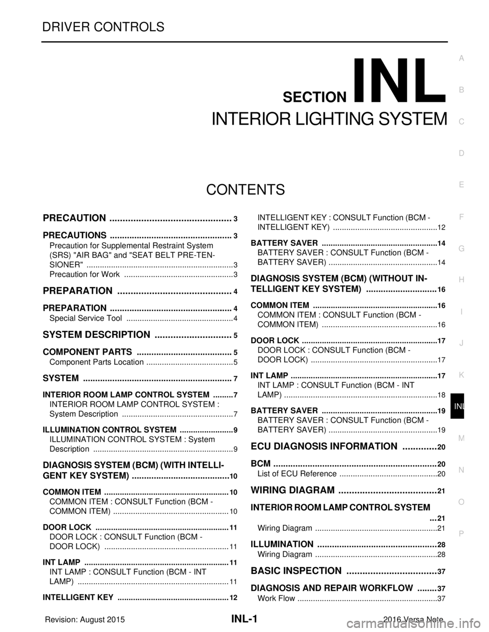
CONTENTS
INTERIOR LIGHTING SYSTEM
PRECAUTION ....... ........................................3
PRECAUTIONS .............................................. .....3
Precaution for Supplemental Restraint System
(SRS) "AIR BAG" and "SEAT BELT PRE-TEN-
SIONER" ............................................................. ......
3
Precaution for Work ..................................................3
PREPARATION ............................................4
PREPARATION .............................................. .....4
Special Service Tool ........................................... ......4
SYSTEM DESCRIPTION ..............................5
COMPONENT PARTS ................................... .....5
Component Parts Location .................................. ......5
SYSTEM ..............................................................7
INTERIOR ROOM LAMP CONTROL SYSTEM .... ......7
INTERIOR ROOM LAMP CONTROL SYSTEM :
System Description ...................................................
7
ILLUMINATION CONTROL SYSTEM ................... ......9
ILLUMINATION CONTROL SYSTEM : System
Description ................................................................
9
DIAGNOSIS SYSTEM (BCM) (WITH INTELLI-
GENT KEY SYSTEM) .........................................
10
COMMON ITEM ..................................................... ....10
COMMON ITEM : CONSULT Function (BCM -
COMMON ITEM) .....................................................
10
DOOR LOCK ......................................................... ....11
DOOR LOCK : CONSULT Function (BCM -
DOOR LOCK) .........................................................
11
INT LAMP .............................................................. ....11
INT LAMP : CONSULT Function (BCM - INT
LAMP) .....................................................................
11
INTELLIGENT KEY ............................................... ....12
INTELLIGENT KEY : CONSULT Function (BCM -
INTELLIGENT KEY) ................................................
12
BATTERY SAVER ................................................. ....14
BATTERY SAVER : CONSULT Function (BCM -
BATTERY SAVER) ..................................................
14
DIAGNOSIS SYSTEM (BCM) (WITHOUT IN-
TELLIGENT KEY SYSTEM) .............................
16
COMMON ITEM ..................................................... ....16
COMMON ITEM : CONSULT Function (BCM -
COMMON ITEM) .....................................................
16
DOOR LOCK .......................................................... ....17
DOOR LOCK : CONSULT Function (BCM -
DOOR LOCK) ..........................................................
17
INT LAMP ............................................................... ....17
INT LAMP : CONSULT Function (BCM - INT
LAMP) ......................................................................
18
BATTERY SAVER ................................................. ....19
BATTERY SAVER : CONSULT Function (BCM -
BATTERY SAVER) ..................................................
19
ECU DIAGNOSIS INFO RMATION ..............20
BCM ...................................................................20
List of ECU Reference ......................................... ....20
WIRING DIAGRAM ......................................21
INTERIOR ROOM LAMP CONTROL SYSTEM
...
21
Wiring Diagram .................................................... ....21
ILLUMINATION .................................................28
Wiring Diagram ........................................................28
BASIC INSPECTION ...................................37
DIAGNOSIS AND REPAIR WORKFLOW ........37
Work Flow ............................................................ ....37
Revision: August 2015 2016 Versa Note
cardiagn.com
Page 2152 of 3641
INT-1
BODY INTERIOR
C
DE
F
G H
I
K L
M
SECTION INT
A
B
INT
N
O P
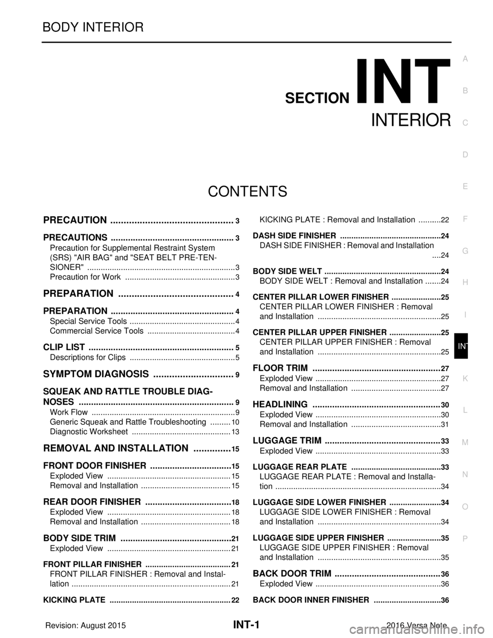
CONTENTS
INTERIOR
PRECAUTION ....... ........................................3
PRECAUTIONS .............................................. .....3
Precaution for Supplemental Restraint System
(SRS) "AIR BAG" and "SEAT BELT PRE-TEN-
SIONER" ............................................................. ......
3
Precaution for Work ..................................................3
PREPARATION ............................................4
PREPARATION .............................................. .....4
Special Service Tools .......................................... ......4
Commercial Service Tools ........................................4
CLIP LIST ............................................................5
Descriptions for Clips ................................................5
SYMPTOM DIAGNOSIS ...............................9
SQUEAK AND RATTLE TROUBLE DIAG-
NOSES ........................ ........................................
9
Work Flow ........................................................... ......9
Generic Squeak and Rattle Troubleshooting ..........10
Diagnostic Worksheet .............................................13
REMOVAL AND INSTALLATION ...............15
FRONT DOOR FINISHER .............................. ....15
Exploded View .................................................... ....15
Removal and Installation .........................................15
REAR DOOR FINISHER ................................ ....18
Exploded View .................................................... ....18
Removal and Installation .........................................18
BODY SIDE TRIM .......................................... ....21
Exploded View .................................................... ....21
FRONT PILLAR FINISHER ................................... ....21
FRONT PILLAR FINISHER : Removal and Instal-
lation .................................................................... ....
21
KICKING PLATE ................................................... ....22
KICKING PLATE : Removal and Installation ...........22
DASH SIDE FINISHER .......................................... ....24
DASH SIDE FINISHER : Removal and Installation
....
24
BODY SIDE WELT ................................................. ....24
BODY SIDE WELT : Removal and Installation ........24
CENTER PILLAR LOWER FINISHER ................... ....25
CENTER PILLAR LOWER FINISHER : Removal
and Installation ........................................................
25
CENTER PILLAR UPPER FINISHER ........................25
CENTER PILLAR UPPER FINISHER : Removal
and Installation .................................................... ....
25
FLOOR TRIM ....................................................27
Exploded View .........................................................27
Removal and Installation .........................................27
HEADLINING ....................................................30
Exploded View .........................................................30
Removal and Installation .........................................31
LUGGAGE TRIM ...............................................33
Exploded View .........................................................33
LUGGAGE REAR PLATE ..................................... ....33
LUGGAGE REAR PLATE : Removal and Installa-
tion ...........................................................................
34
LUGGAGE SIDE LOWER FINISHER .................... ....34
LUGGAGE SIDE LOWER FINISHER : Removal
and Installation ........................................................
34
LUGGAGE SIDE UPPER FINISHER .........................35
LUGGAGE SIDE UPPER FINISHER : Removal
and Installation .................................................... ....
35
BACK DOOR TRIM ...........................................36
Exploded View ..................................................... ....36
BACK DOOR INNER FINISHER ........................... ....36
Revision: August 2015 2016 Versa Note
cardiagn.com