2016 NISSAN NOTE relay
[x] Cancel search: relayPage 524 of 3641
![NISSAN NOTE 2016 Service Repair Manual BRC-76
< DTC/CIRCUIT DIAGNOSIS >[VDC/TCS/ABS]
C1111 ABS MOTOR, MOTOR RELAY SYSTEM
5. Turn the ignition switch OFF
→ ON → OFF.
NOTE:
Wait at least 10 seconds after turning ignition switch OFF or](/manual-img/5/57363/w960_57363-523.png "NISSAN NOTE 2016 Service Repair Manual BRC-76
< DTC/CIRCUIT DIAGNOSIS >[VDC/TCS/ABS]
C1111 ABS MOTOR, MOTOR RELAY SYSTEM
5. Turn the ignition switch OFF
→ ON → OFF.
NOTE:
Wait at least 10 seconds after turning ignition switch OFF or")
BRC-76
< DTC/CIRCUIT DIAGNOSIS >[VDC/TCS/ABS]
C1111 ABS MOTOR, MOTOR RELAY SYSTEM
5. Turn the ignition switch OFF
→ ON → OFF.
NOTE:
Wait at least 10 seconds after turning ignition switch OFF or ON.
>> Inspection End.
Revision: August 2015 2016 Versa Note
cardiagn.com
Page 542 of 3641
![NISSAN NOTE 2016 Service Repair Manual BRC-94
< DTC/CIRCUIT DIAGNOSIS >[VDC/TCS/ABS]
C1140 ACTUATOR RELAY SYSTEM
C1140 ACTUATOR RELAY SYSTEM
DTC DescriptionINFOID:0000000012430875
DTC DETECTION LOGIC
POSSIBLE CAUSE
NOTE:
Confirm if DTC is](/manual-img/5/57363/w960_57363-541.png "NISSAN NOTE 2016 Service Repair Manual BRC-94
< DTC/CIRCUIT DIAGNOSIS >[VDC/TCS/ABS]
C1140 ACTUATOR RELAY SYSTEM
C1140 ACTUATOR RELAY SYSTEM
DTC DescriptionINFOID:0000000012430875
DTC DETECTION LOGIC
POSSIBLE CAUSE
NOTE:
Confirm if DTC is")
BRC-94
< DTC/CIRCUIT DIAGNOSIS >[VDC/TCS/ABS]
C1140 ACTUATOR RELAY SYSTEM
C1140 ACTUATOR RELAY SYSTEM
DTC DescriptionINFOID:0000000012430875
DTC DETECTION LOGIC
POSSIBLE CAUSE
NOTE:
Confirm if DTC is PAST or CRNT. If DTC is CRNT, proceed with Diagnosis Procedure. If DTC is PAST, clear
the DTC. Do not replace the
ABS actuator and electric unit (control unit) for a PAST DTC.
DTC CONFIRMATION PROCEDURE
1.PRECONDITIONING
If “DTC CONFIRMATION PROCEDURE” has been previously conducted, always turn the ignition switch OFF
and wait at least 10 seconds before conducting the next test.
>> GO TO 2.
2.CHECK DTC DETECTION
With CONSULT
1. Turn the ignition switch OFF. NOTE:
Wait at least 10 seconds after turning ignition switch OFF.
2. Start the engine. NOTE:
Wait at least 10 seconds after starting the engine.
3. Perform “Self Diagnostic Result” of “ABS”.
Is DTC
“C1140” detected?
YES-1 >> “C1140” is displayed as “CRNT”: Proceed to BRC-94, "Diagnosis Procedure".
YES-2 >> “C1140” is displayed as “PAST”: Inspection End (Erase “Self Diagnostic Result” of “ABS”).
NO-1 >> To check malfunction symptom before repair: Refer to GI-42, "
Intermittent Incident".
NO-2 >> Confirmation after repair: Inspection End.
Diagnosis ProcedureINFOID:0000000012430876
1.CHECK CONNECTOR
1. Turn the ignition switch OFF.
2. Check the ABS actuator and electric unit (contro l unit) harness connector for disconnection or looseness.
Is the inspection result normal?
YES >> GO TO 3.
NO >> Repair / replace harness or connector, securely lock the connector, and GO TO 2.
2.PERFORM SELF-DIAGNOSIS
DTC Display Item
(Trouble diagnosis content) Malfunction detected condition
C1140 ACTUATOR RLY
(Actuator relay) When a malfunction is detected in actuator relay.
PAST DTC
CRNT DTC
• Harness or connector
• ABS actuator and electric unit (control unit) power supply sys-
tem
•Fuse
• Fusible link
•Battery • Harness or connector
• ABS actuator and electric unit (control unit)
• ABS actuator and electric unit
(control unit) power supply sys-
tem
•Fuse
• Fusible link
•Battery
Revision: August 2015 2016 Versa Note
cardiagn.com
Page 543 of 3641
![NISSAN NOTE 2016 Service Repair Manual C1140 ACTUATOR RELAY SYSTEMBRC-95
< DTC/CIRCUIT DIAGNOSIS > [VDC/TCS/ABS]
C
D
E
G H
I
J
K L
M A
B
BRC
N
O P
With CONSULT
1. Turn the ignition switch OFF.
NOTE:
Wait at least 10 seconds after turning i](/manual-img/5/57363/w960_57363-542.png "NISSAN NOTE 2016 Service Repair Manual C1140 ACTUATOR RELAY SYSTEMBRC-95
< DTC/CIRCUIT DIAGNOSIS > [VDC/TCS/ABS]
C
D
E
G H
I
J
K L
M A
B
BRC
N
O P
With CONSULT
1. Turn the ignition switch OFF.
NOTE:
Wait at least 10 seconds after turning i")
C1140 ACTUATOR RELAY SYSTEMBRC-95
< DTC/CIRCUIT DIAGNOSIS > [VDC/TCS/ABS]
C
D
E
G H
I
J
K L
M A
B
BRC
N
O P
With CONSULT
1. Turn the ignition switch OFF.
NOTE:
Wait at least 10 seconds after turning ignition switch OFF.
2. Start the engine.
NOTE:
Wait at least 10 seconds after starting the engine.
3. Perform “Self Diagnostic Result” of “ABS”.
Is DTC
“C1140” detected?
YES >> GO TO 3.
NO >> Inspection End.
3.CHECK ABS ACTUATOR AND ELECTRIC UNIT (CONTROL UNIT) POWER SUPPLY AND GROUND CIR-
CUIT
Check the ABS actuator and electr ic unit (control unit) power supply and ground circuits. Refer to BRC-121,
"Diagnosis Procedure".
Is the inspection result normal?
YES >> GO TO 4.
NO >> Repair / replace harness, connector, fuse, or fusible link.
4.CHECK TERMINAL
Check the ABS actuator and electric unit (control unit) pin terminals for damage or loose connection with har-
ness connector.
Is the inspection result normal?
YES >> Replace the ABS actuator and electric unit (control unit). Refer to BRC-144, "Removal and Instal-
lation".
NO >> Repair / replace harness, connector, or terminal.
Revision: August 2015 2016 Versa Note
cardiagn.com
Page 569 of 3641
![NISSAN NOTE 2016 Service Repair Manual POWER SUPPLY AND GROUND CIRCUITBRC-121
< DTC/CIRCUIT DIAGNOSIS > [VDC/TCS/ABS]
C
D
E
G H
I
J
K L
M A
B
BRC
N
O P
POWER SUPPLY AND GROUND CIRCUIT
Diagnosis ProcedureINFOID:0000000012430902
1.CHECK ABS](/manual-img/5/57363/w960_57363-568.png "NISSAN NOTE 2016 Service Repair Manual POWER SUPPLY AND GROUND CIRCUITBRC-121
< DTC/CIRCUIT DIAGNOSIS > [VDC/TCS/ABS]
C
D
E
G H
I
J
K L
M A
B
BRC
N
O P
POWER SUPPLY AND GROUND CIRCUIT
Diagnosis ProcedureINFOID:0000000012430902
1.CHECK ABS")
POWER SUPPLY AND GROUND CIRCUITBRC-121
< DTC/CIRCUIT DIAGNOSIS > [VDC/TCS/ABS]
C
D
E
G H
I
J
K L
M A
B
BRC
N
O P
POWER SUPPLY AND GROUND CIRCUIT
Diagnosis ProcedureINFOID:0000000012430902
1.CHECK ABS ACTUATOR AND ELECTRIC UNIT (CONTROL UNIT) IGNITION POWER SUPPLY (1)
1. Turn the ignition switch OFF.
2. Disconnect ABS actuator and electric unit (control unit) harness connector.
3. Check the voltage between ABS actuator and elec tric unit (control unit) harness connector and ground.
4. Turn the ignition switch ON NOTE:
Start the engine.
5. Check the voltage between ABS actuator and elec tric unit (control unit) harness connector and ground.
Is the inspection result normal?
YES >> GO TO 3.
NO >> GO TO 2.
2.CHECK ABS ACTUATOR AND ELECTRIC UNIT (CONTROL UNIT) IGNITION POWER SUPPLY CIRCUIT
1. Turn the ignition switch OFF.
2. Check the 10A fuse (50).
3. Disconnect IPDM E/R harness connector.
4. Check the continuity between ABS actuator and elec tric unit (control unit) harness connector and IPDM E/
R.
5. Check the continuity between ABS actuator and electric unit (control unit) harness connector and ground.
Is the inspection result normal?
YES >> Perform trouble diagnosis for ignition power supply.
NO >> Repair / replace harness, connector, or fuse.
3.CHECK MOTOR AND MOTOR RELAY POWER SUPPLY
1. Turn the ignition switch OFF.
2. Check the voltage between ABS actuator and elec tric unit (control unit) harness connector and ground.
3. Turn the ignition switch ON. NOTE:
ABS actuator and electric unit (control unit) —Voltag e
(Approx.)
Connector Terminal
E33 6Ground 0 V
ABS actuator and electric unit (control unit)
—Voltag e
(Approx.)
Connector Terminal
E33 6GroundBattery voltage
ABS actuator and electric unit (control unit) IPDM E/R
Continuity
Connector TerminalConnectorTerminal
E33 6E4520Yes
ABS actuator and electric unit (control unit)
—Con tin uit y
Connector Terminal
E33 6Ground No
ABS actuator and electric unit (control unit)
—Voltag e
(Approx.)
Connector Terminal
E33 1GroundBattery voltage
Revision: August 2015 2016 Versa Note
cardiagn.com
Page 570 of 3641
![NISSAN NOTE 2016 Service Repair Manual BRC-122
< DTC/CIRCUIT DIAGNOSIS >[VDC/TCS/ABS]
POWER SUPPLY AND GROUND CIRCUIT
Start the engine.
4. Check the voltage between ABS actuator and elec tric unit (control unit) harness connector and groun](/manual-img/5/57363/w960_57363-569.png "NISSAN NOTE 2016 Service Repair Manual BRC-122
< DTC/CIRCUIT DIAGNOSIS >[VDC/TCS/ABS]
POWER SUPPLY AND GROUND CIRCUIT
Start the engine.
4. Check the voltage between ABS actuator and elec tric unit (control unit) harness connector and groun")
BRC-122
< DTC/CIRCUIT DIAGNOSIS >[VDC/TCS/ABS]
POWER SUPPLY AND GROUND CIRCUIT
Start the engine.
4. Check the voltage between ABS actuator and elec tric unit (control unit) harness connector and ground.
Is the inspection result normal?
YES >> GO TO 5.
NO >> GO TO 4.
4.CHECK MOTOR AND MOTOR RE LAY POWER SUPPLY CIRCUIT
1. Turn the ignition switch OFF.
2. Check the 40A fusible link (I).
3. Check the continuity and short circuit between ABS actuator and electric unit (control unit) harness con-
nector terminal 1 and 40A fusible link (I).
Is the inspection result normal?
YES >> Perform trouble diagnosis for battery power supply.
NO >> Repair / replace harness, connector, or fusible link.
5.CHECK ACTUATOR RELAY, ABS IN VALVE, ABS OUT VALVE POWER SUPPLY
1. Turn the ignition switch OFF.
2. Check the voltage between ABS actuator and elec tric unit (control unit) harness connector and ground.
3. Turn the ignition switch ON NOTE:
Start the engine.
4. Check the voltage between ABS actuator and elec tric unit (control unit) harness connector and ground.
Is the inspection result normal?
YES >> GO TO 7.
NO >> GO TO 6.
6.CHECK ACTUATOR RELAY, ABS IN VALV E, ABS OUT VALVE POWER SUPPLY CIRCUIT
1. Turn the ignition switch OFF.
2. Check the 30A fusible link (M).
3. Check the continuity and short circuit between ABS actuator and electric unit (control unit) harness con-
nector terminal 25 and 30A fusible link (M).
Is the inspection result normal?
YES >> Perform trouble diagnosis for battery power supply.
NO >> Repair / replace harness, connector, or fusible link.
7.CHECK ABS ACTUATOR AND ELECTRIC UNIT (CONTROL UNIT) GROUND CIRCUIT
Check the continuity between ABS actuator and electric unit (control unit) harness connector and the ground.
ABS actuator and electric unit (control unit)
—Vol tag e
(Approx.)
Connector Terminal
E33 1GroundBattery voltage
ABS actuator and electric unit (control unit)
—Vo l ta g e
(Approx.)
Connector Terminal
E33 25GroundBattery voltage
ABS actuator and electric unit (control unit)
—Vo l ta g e
(Approx.)
Connector Terminal
E33 25GroundBattery voltage
Revision: August 2015 2016 Versa Note
cardiagn.com
Page 652 of 3641

DEF-1
DRIVER CONTROLS
C
DE
F
G H
I
J
K
M
SECTION DEF
A
B
DEF
N
O P
CONTENTS
DEFOGGER
PRECAUTION ....... ........................................3
PRECAUTIONS .............................................. .....3
Precaution for Supplemental Restraint System
(SRS) "AIR BAG" and "SEAT BELT PRE-TEN-
SIONER" ............................................................. ......
3
SYSTEM DESCRIPTION ..............................4
COMPONENT PARTS ................................... .....4
Component Parts Location .................................. ......4
Rear window defogger ..............................................5
Door mirror defogger .................................................5
SYSTEM ..............................................................6
System Description ............................................. ......6
DIAGNOSIS SYSTEM (BCM) (WITH INTELLI-
GENT KEY SYSTEM) ..........................................
7
COMMON ITEM ..................................................... ......7
COMMON ITEM : CONSULT Function (BCM -
COMMON ITEM) .......................................................
7
REAR DEFOGGER ............................................... ......8
REAR DEFOGGER : CONSULT Function (BCM -
REAR DEFOGGER) ........................................... ......
8
DIAGNOSIS SYSTEM (BCM) (WITHOUT IN-
TELLIGENT KEY SYSTEM) ................................
9
COMMON ITEM ..................................................... ......9
COMMON ITEM : CONSULT Function (BCM -
COMMON ITEM) .......................................................
9
REAR DEFOGGER ............................................... ....10
REAR DEFOGGER : CONSULT Function (BCM -
REAR DEFOGGER) ........................................... ....
10
ECU DIAGNOSIS INFORMATION ..............11
BCM ................................................................ ....11
List of ECU Reference ........................................ ....11
WIRING DIAGRAM ......................................12
REAR WINDOW DE FOGGER SYSTEM ..........12
Wiring Diagram .................................................... ....12
BASIC INSPECTION ...................................17
DIAGNOSIS AND REPAIR WORK FLOW .......17
Work Flow ............................................................ ....17
DTC/CIRCUIT DIAGNOSIS .........................20
REAR WINDOW DEFOGGER SWITCH ...........20
Description ........................................................... ....20
Component Function Check ....................................20
Diagnosis Procedure ...............................................20
Component Inspection .............................................21
REAR WINDOW DEFOGGER RELAY .............22
Description ...............................................................22
Component Function Check ....................................22
Diagnosis Procedure ...............................................22
Component Inspection .............................................23
REAR WINDOW DEFOGGER POWER SUP-
PLY AND GROUND CIRCUIT ..........................
24
Description ...............................................................24
Component Function Check ....................................24
Diagnosis Procedure ...............................................24
Component Inspection .............................................25
DRIVER SIDE DOOR MIRROR DEFOGGER ...26
Description ...............................................................26
Component Function Check ....................................26
Diagnosis Procedure ...............................................26
Component Inspection .............................................27
PASSENGER SIDE DOOR MIRROR DEFOG-
GER ...................................................................
28
Description ...............................................................28
Component Function Check ....................................28
Diagnosis Procedure ...............................................28
Revision: August 2015 2016 Versa Note
cardiagn.com
Page 656 of 3641
COMPONENT PARTSDEF-5
< SYSTEM DESCRIPTION >
C
DE
F
G H
I
J
K
M A
B
DEF
N
O P
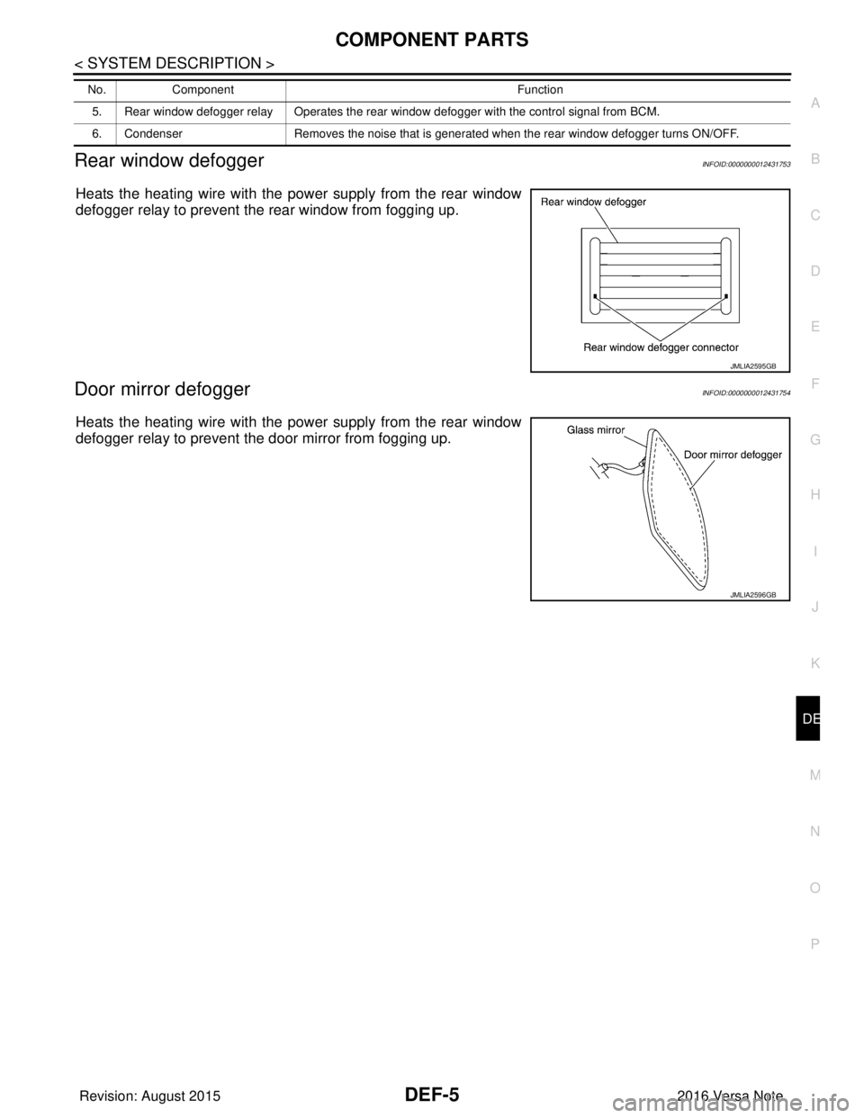
Rear window defoggerINFOID:0000000012431753
Heats the heating wire with the pow er supply from the rear window
defogger relay to prevent the rear window from fogging up.
Door mirror defoggerINFOID:0000000012431754
Heats the heating wire with the pow er supply from the rear window
defogger relay to prevent the door mirror from fogging up.
5. Rear window defogger relay Operates the rear window defogger with the control signal from BCM.
6. Condenser Removes the noise that is generated when the rear window defogger turns ON/OFF.
No.
Component Function
JMLIA2595GB
JMLIA2596GB
Revision: August 2015 2016 Versa Note
cardiagn.com
Page 657 of 3641
DEF-6
< SYSTEM DESCRIPTION >
SYSTEM
SYSTEM
System DescriptionINFOID:0000000012431755
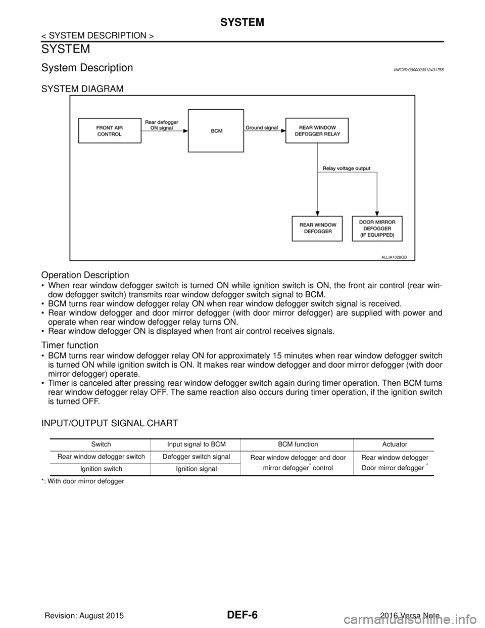
SYSTEM DIAGRAM
Operation Description
• When rear window defogger switch is turned ON while ignition switch is ON, the front air control (rear win-dow defogger switch) transmits rear window defogger switch signal to BCM.
• BCM turns rear window defogger relay ON when rear window defogger switch signal is received.
• Rear window defogger and door mirror defogger (with door mirror defogger) are supplied with power and operate when rear window defogger relay turns ON.
• Rear window defogger ON is displayed when front air control receives signals.
Timer function
• BCM turns rear window defogger relay ON for appr oximately 15 minutes when rear window defogger switch
is turned ON while ignition switch is ON. It makes rear window defogger and door mirror defogger (with door
mirror defogger) operate.
• Timer is canceled after pressing rear window defogger switch again during timer operation. Then BCM turns rear window defogger relay OFF. The same reaction also occurs during timer operation, if the ignition switch
is turned OFF.
INPUT/OUTPUT SIGNAL CHART
*: With door mirror defogger
ALLIA1028GB
Switch Input signal to BCM BCM functionActuator
Rear window defogger switch Defogger switch signal Rear window defogger and door
mirror defogger
* control Rear window defogger
Door mirror defogger *Ignition switch Ignition signal
Revision: August 2015 2016 Versa Note
cardiagn.com