2016 NISSAN NOTE change key battery
[x] Cancel search: change key batteryPage 2107 of 3641
![NISSAN NOTE 2016 Service Repair Manual DIAGNOSIS SYSTEM (BCM) (WITH INTELLIGENT KEY SYSTEM)
INL-13
< SYSTEM DESCRIPTION >
C
D E
F
G H
I
J
K
M A
B
INL
N
O P
ACTIVE TEST
BRAKE SW 2 [On/Off] Indicates condition of brake switch.
DETE/CANCL SW](/manual-img/5/57363/w960_57363-2106.png "NISSAN NOTE 2016 Service Repair Manual DIAGNOSIS SYSTEM (BCM) (WITH INTELLIGENT KEY SYSTEM)
INL-13
< SYSTEM DESCRIPTION >
C
D E
F
G H
I
J
K
M A
B
INL
N
O P
ACTIVE TEST
BRAKE SW 2 [On/Off] Indicates condition of brake switch.
DETE/CANCL SW")
DIAGNOSIS SYSTEM (BCM) (WITH INTELLIGENT KEY SYSTEM)
INL-13
< SYSTEM DESCRIPTION >
C
D E
F
G H
I
J
K
M A
B
INL
N
O P
ACTIVE TEST
BRAKE SW 2 [On/Off] Indicates condition of brake switch.
DETE/CANCL SW [On/Off] ×Indicates condition of P (park) position.
SFT PN/N SW [On/Off] ×Indicates condition of P (park) or N (neutral) position.
UNLK SEN -DR [On/Off] ×Indicates condition of door unlock sensor.
PUSH SW -IPDM [On/Off] Indicates condition of push-button ignition switch received from IPDM E/R on
CAN communication line.
IGN RLY1 -F/B [On/Off] Indicates condition of ignition relay 1 received from IPDM E/R on CAN commu-
nication line.
DETE SW -IPDM [On/Off] Indicates condition of detent switch received from TCM on CAN communication
line.
SFT PN -IPDM [On/Off] Indicates condition of P (park) or N (neutral) position from TCM on CAN com-
munication line.
SFT P -MET [On/Off] Indicates condition of P (park) position from TCM on CAN communication line.
SFT N -MET [On/Off] Indicates condition of N (neutral) position from IPDM E/R on CAN communica-
tion line.
ENGINE STATE [Stop/Start/Crank/Run] ×Indicates condition of engine state from ECM on CAN communication line.
VEH SPEED 1 [mph/km/h] ×Indicates condition of vehicle speed si
gnal received from ABS on CAN commu-
nication line.
VEH SPEED 2 [mph/km/h] ×Indicates condition of vehicle speed signal received from combination meter on
CAN communication line.
DOOR STAT -DR [LOCK/READY/UNLK] ×Indicates condition of driver side door status.
DOOR STAT -AS [LOCK/READY/UNLK] ×Indicates condition of passenger side door status.
ID OK FLAG [Set/Reset] Indicates condition of Intelligent Key ID.
PRMT ENG STRT [Set/Reset] Indicates condition of engine start possibility.
RKE OPE COUN1 [0-19] ×When remote keyless entry receiver receives the signal transmitted while oper-
ating on Intelligent Key, the numerical value start changing.
RKE OPE COUN2 [0-19] ×When remote keyless entry receiver receives the signal transmitted while oper-
ating on Intelligent Key, the numerical value start changing.
RKE-LOCK [On/Off] Indicates condition of lock signal from Intelligent Key.
RKE-UNLOCK [On/Off] Indicates condition of unlock signal from Intelligent Key.
RKE-PANIC [On/Off] Indicates condition of panic signal from Intelligent Key.
RKE-MODE CHG [On/Off] Indicates condition of mode change signal from Intelligent Key.
Monitor Item [Unit]
Main Description
Test Item Description
INSIDE BUZZER This test is able to check combination meter warning chime operation [Take Out/Knob/Key/
Off].
LCD This test is able to check combination me
ter display information [Off/LK WN/OUTKEY/NO
KY/BATT/INSRT/SFT P/ROTAT/ID NG/B&P I/B&P N].
BATTERY SAVER This test is able to check battery saver operation [On/Off].
ENGINE SW ILLUMI This test is able to check push-button ignition switch START indicator operation [On/Off].
PUSH SWITCH INDICATOR This test is able to check push-button ignition switch indicator operation [On/Off].
INT LAMP This test is able to check interior room lamp operation [On/Off].
INDICATOR This test is able to check combination mete r warning lamp operation [KEY ON/KEY IND/Off].
FLASHER This test is able to check hazard lamp operation [LH/RH/Off].
OUTSIDE BUZZER This test is able to check Intelligent Key warning buzzer operation [On/Off].
HORN This test is able to check horn operation [On].
P RANGE This test is able to check CVT shift selector illumination operation [On/Off].
Revision: August 2015 2016 Versa Note
cardiagn.com
Page 2110 of 3641

INL-16
< SYSTEM DESCRIPTION >
DIAGNOSIS SYSTEM (BCM) (WITHOUT INTELLIGENT KEY SYSTEM)
DIAGNOSIS SYSTEM (BCM) (WITHOUT INTELLIGENT KEY SYSTEM)
COMMON ITEM
COMMON ITEM : CONSULT Function (BCM - COMMON ITEM)INFOID:0000000012542974
APPLICATION ITEM
CONSULT performs the following functions via CAN communication with BCM.
SYSTEM APPLICATION
BCM can perform the following functions.
Direct Diagnostic Mode Description
ECU Identification The BCM part number is displayed.
Self Diagnostic Result The BCM self diagnostic results are displayed.
Data Monitor The BCM input/output data is displayed in real time.
Active Test The BCM activates outputs to test components.
Work support The settings for BCM functions can be changed.
Configuration • The vehicle specification can be read and saved.
• The vehicle specification can be written when replacing BCM.
CAN DIAG SUPPORT MNTR The result of transmit/receive diagnosis of CAN communication is displayed.
System Sub System Direct Diagnostic Mode
ECU Identification
Self Diagnostic Result
Data Monitor
Active Test
Work support
Configuration
CAN DIAG SUPPORT MNTR
Door lock
DOOR LOCK ×××
Rear window defogger REAR DEFOGGER ××
Warning chime BUZZER ××
Interior room lamp timer INT LAMP ×××
Remote keyless entry system MULTI REMOTE ENT ×××
Exterior lamp HEAD LAMP ×××
Wiper and washer WIPER ×××
Turn signal and hazard warning lamps FLASHER ××
Air conditioner AIR CONDITIONER ×
Combination switch COMB SW ×
BCM BCM× × ×××
Immobilizer IMMU ×××
Interior room lamp battery saver BATTERY SAVER ×××
Vehicle security system THEFT ALM ××
RAP system RETAINED PWR ××
Signal buffer system SIGNAL BUFFER ×
TPMS AIR PRESSURE MONITOR ××××
Panic alarm system PANIC ALARM ×
Revision: August 2015 2016 Versa Note
cardiagn.com
Page 2324 of 3641
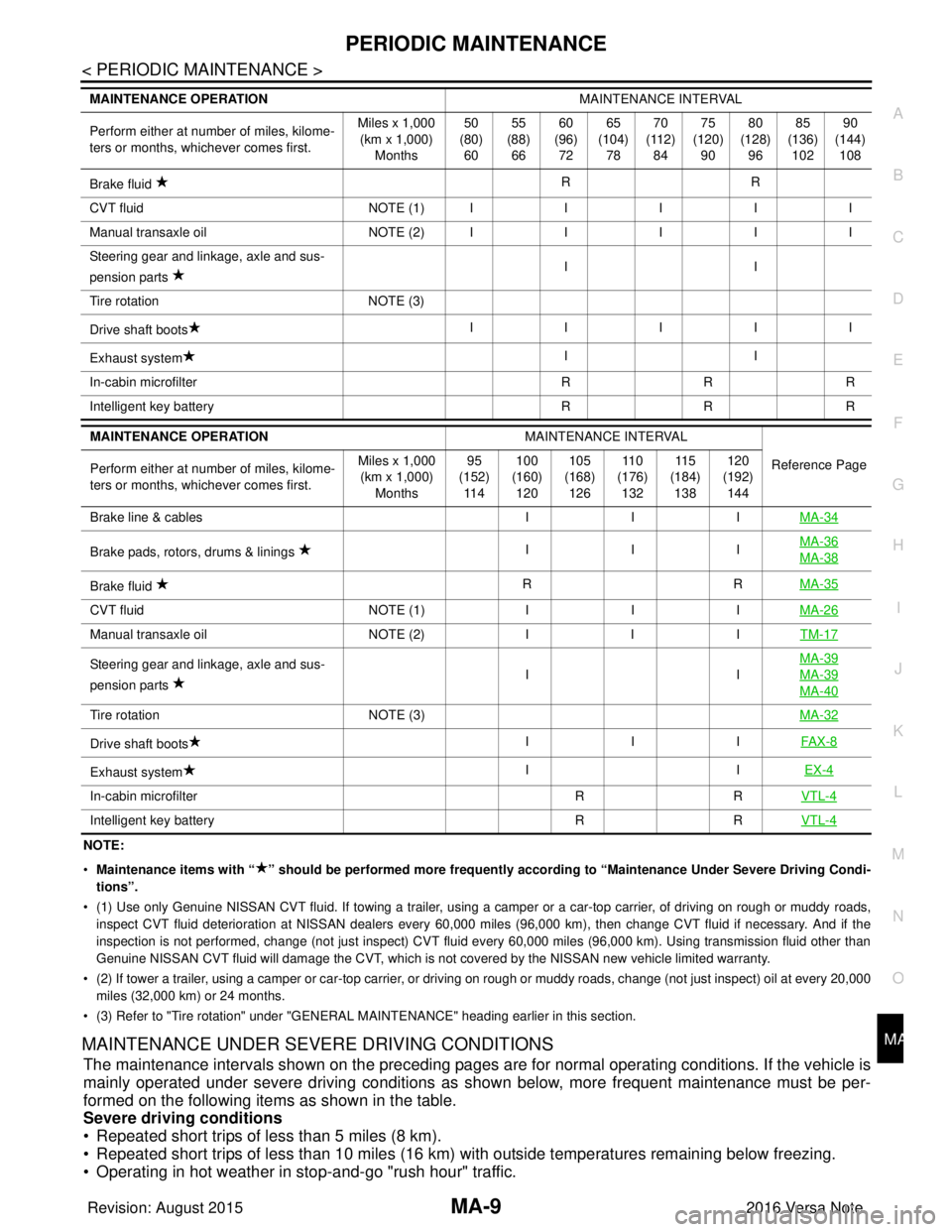
PERIODIC MAINTENANCEMA-9
< PERIODIC MAINTENANCE >
C
DE
F
G H
I
J
K L
M B
MA
N
O A
NOTE:
•
Maintenance items with “ ” shoul d be performed more frequently according to “Maintenance Under Severe Driving Condi-
tions”.
• (1) Use only Genuine NISSAN CVT fluid. If towing a trailer, using a camper or a car-top carrier, of driving on rough or muddy roads,
inspect CVT fluid deterioration at NISSAN dealers every 60,000 miles (96,000 km), then change CVT fluid if necessary. And if th e
inspection is not performed, change (not just inspect) CVT fluid every 60,000 miles (96,000 km). Using transmission fluid other than
Genuine NISSAN CVT fluid will damage the CVT, which is not covered by the NISSAN new vehicle limited warranty.
• (2) If tower a trailer, using a camper or car-top carrier, or driving on rough or muddy roads, change (not just inspect) oil a t every 20,000
miles (32,000 km) or 24 months.
• (3) Refer to "Tire rotation" under "GENERAL MAINTENANCE" heading earlier in this section.
MAINTENANCE UNDER SEVERE DRIVING CONDITIONS
The maintenance intervals shown on the preceding pages are for normal operating conditions. If the vehicle is
mainly operated under severe driving conditions as shown below, more frequent maintenance must be per-
formed on the following items as shown in the table.
Severe driving conditions
• Repeated short trips of less than 5 miles (8 km).
• Repeated short trips of less than 10 miles (16 km) wi th outside temperatures remaining below freezing.
• Operating in hot weather in stop-and-go "rush hour" traffic.
Brake fluid RR
C VT flu id NO TE (1)IIIII
M anu al t ra nsa xle o il NO TE (2)IIIII
Steering gear and linkage, axle and sus-
pension parts II
Tire rotation NOTE (3)
Drive shaft boots IIIII
Exhaust system II
In-cabin microfilter RRR
Intelligent key battery RRR
MAINTENANCE OPERATION MAINTENANCE INTERVAL
Reference Page
Perform either at number of miles, kilome-
ters or months, whichever comes first. Miles x 1,000
(km x 1,000) Months 95
(152) 11 4 100
(160) 120 105
(168) 126 11 0
(176) 132 11 5
(184) 138 120
(192) 144
Brake line & cables IIIMA-34
Brake pads, rotors, drums & linings IIIMA-36MA-38
Brake fluid
RR
MA-35
CVT fluid NOTE (1)IIIMA-26
Manual transaxle oil NOTE (2)IIITM-17
Steering gear and linkage, axle and sus-
pension parts IIMA-39MA-39
MA-40
Tire rotation
NOTE (3) MA-32
Drive shaft boots III
FAX-8
Exhaust system II
EX-4
In-cabin microfilter RRVTL-4
Intelligent key battery RRVTL-4
MAINTENANCE OPERATION MAINTENANCE INTERVAL
Perform either at number of miles, kilome-
ters or months, whichever comes first. Miles x 1,000
(km x 1,000)
Months 50
(80)
60 55
(88)
66 60
(96)
72 65
(104)
78 70
(112)
84 75
(120)
90 80
(128)
96 85
(136)
102 90
(144)
108
Revision: August 2015 2016 Versa Note
cardiagn.com
Page 2537 of 3641
![NISSAN NOTE 2016 Service Repair Manual PCS-34
< SYSTEM DESCRIPTION >[POWER DISTRIBUTION SYSTEM]
SYSTEM
SYSTEM
POWER DISTRIBUTION SYSTEM
POWER DISTRIBUTION SYSTEM
: System DescriptionINFOID:0000000012433289
SYSTEM DIAGRAM
SYSTEM DESCRIPTIO](/manual-img/5/57363/w960_57363-2536.png "NISSAN NOTE 2016 Service Repair Manual PCS-34
< SYSTEM DESCRIPTION >[POWER DISTRIBUTION SYSTEM]
SYSTEM
SYSTEM
POWER DISTRIBUTION SYSTEM
POWER DISTRIBUTION SYSTEM
: System DescriptionINFOID:0000000012433289
SYSTEM DIAGRAM
SYSTEM DESCRIPTIO")
PCS-34
< SYSTEM DESCRIPTION >[POWER DISTRIBUTION SYSTEM]
SYSTEM
SYSTEM
POWER DISTRIBUTION SYSTEM
POWER DISTRIBUTION SYSTEM
: System DescriptionINFOID:0000000012433289
SYSTEM DIAGRAM
SYSTEM DESCRIPTION
• PDS (POWER DISTRIBUTION SYSTEM) is the system that BCM contro ls with the operation of the push-
button ignition switch and performs the power distribution to each power circuit. This system is used instead
of the mechanical power supply changing mechanism wi th the operation of the conventional key cylinder.
• The push-button ignition switch can be operated when Intelligent Key is in the following condition:
- Intelligent Key is in the detection area of the inside key antenna.
- Intelligent Key backside is contacted to push-button ignition switch.
• The push-button ignition switch operation is input to BCM as a signal. BCM changes the power supply posi-
tion according to the status and operates the following relays to supply power to each power circuit:
- Ignition relay-1
- Ignition relay-2
- Accessory relay-1
- Accessory relay-2
- Blower motor relay NOTE:
The engine switch operation changes due to the conditions of brake pedal, selector lever and vehicle speed.
• The power supply position can be confirmed with the light ing of the indicators in the push-button ignition
switch.
IGNITION BATTERY SAVER SYSTEM
When all the following conditions are met for a period of time, the battery saver system will turn off the power
supply (ignition switch ON/ACC → OFF) to prevent battery discharge.
• Ignition switch is in the ACC or ON position
• Turn signal lamp is not in operation
• Selector lever is in the P (park) position
Reset Condition of Igniti on Battery Saver System
If any of the following conditions are met, the battery saver system is released.
• Ignition switch is not in the ACC or ON position
• Turn signal lamp is in operation
• Selector lever is not in the P (park) position
NOTE:
The ignition battery saver system can be temporarily di sabled, without using CONSULT, to prevent it from
functioning when performing trouble diagnosis. Refer to PCS-53, "
Work Procedure".
POWER SUPPLY POSITION CHANGE TABLE BY PUSH-BUTTON IGNITION SWITCH OPERA-
AWMIA3150GB
Revision: August 2015 2016 Versa Note
cardiagn.com
Page 2540 of 3641
![NISSAN NOTE 2016 Service Repair Manual PCS
DIAGNOSIS SYSTEM (BCM)PCS-37
< SYSTEM DESCRIPTION > [POWER DISTRIBUTION SYSTEM]
C
D
E
F
G H
I
J
K L
B A
O P
N
DIAGNOSIS SYSTEM (BCM)
COMMON ITEM
COMMON ITEM : CONSULT Function (BCM - COMMON ITEM)I](/manual-img/5/57363/w960_57363-2539.png "NISSAN NOTE 2016 Service Repair Manual PCS
DIAGNOSIS SYSTEM (BCM)PCS-37
< SYSTEM DESCRIPTION > [POWER DISTRIBUTION SYSTEM]
C
D
E
F
G H
I
J
K L
B A
O P
N
DIAGNOSIS SYSTEM (BCM)
COMMON ITEM
COMMON ITEM : CONSULT Function (BCM - COMMON ITEM)I")
PCS
DIAGNOSIS SYSTEM (BCM)PCS-37
< SYSTEM DESCRIPTION > [POWER DISTRIBUTION SYSTEM]
C
D
E
F
G H
I
J
K L
B A
O P
N
DIAGNOSIS SYSTEM (BCM)
COMMON ITEM
COMMON ITEM : CONSULT Function (BCM - COMMON ITEM)INFOID:0000000012542491
APPLICATION ITEM
CONSULT performs the following functions via CAN communication with BCM.
SYSTEM APPLICATION
BCM can perform the following functions.
Direct Diagnostic Mode
Description
ECU Identification The BCM part number is displayed.
Self Diagnostic Result The BCM self diagnostic results are displayed.
Data Monitor The BCM input/output data is displayed in real time.
Active Test The BCM activates outputs to test components.
Work support The settings for BCM functions can be changed.
Configuration • The vehicle specification can be read and saved.
• The vehicle specification can be written when replacing BCM.
CAN DIAG SUPPORT MNTR The result of transmit/receive diagnosis of CAN communication is displayed.
System Sub System Direct Diagnostic Mode
ECU Identification
Self Diagnostic Result
Data Monitor
Active Test
Work support
Configuration
CAN DIAG SUPPORT MNTR
Door lock
DOOR LOCK ×××
Rear window defogger REAR DEFOGGER ××
Warning chime BUZZER ××
Interior room lamp timer INT LAMP ×××
Exterior lamp HEAD LAMP ×××
Wiper and washer WIPER ×××
Turn signal and hazard warning lamps FLASHER ×××
Air conditioner AIR CONDITIONER ×
Intelligent Key system INTELLIGENT KEY ××××
Combination switch COMB SW ×
BCM BCM× × ×××
Immobilizer IMMU ××××
Interior room lamp battery saver BATTERY SAVER ×××
Vehicle security system THEFT ALM ××
RAP system RETAINED PWR ×
Signal buffer system SIGNAL BUFFER ×
TPMS AIR PRESSURE MONITOR ××××
Panic alarm system PANIC ALARM ×
Revision: August 2015 2016 Versa Note
cardiagn.com
Page 2670 of 3641

DIAGNOSIS SYSTEM (BCM) (WITH INTELLIGENT KEY SYSTEM)
PWC-9
< SYSTEM DESCRIPTION >
C
D E
F
G H
I
J
L
M A
B
PWC
N
O P
DIAGNOSIS SYSTEM (BCM) (WIT H INTELLIGENT KEY SYSTEM)
COMMON ITEM
COMMON ITEM : CONSULT Function (BCM - COMMON ITEM)INFOID:0000000012542484
APPLICATION ITEM
CONSULT performs the following functions via CAN communication with BCM.
SYSTEM APPLICATION
BCM can perform the following functions.
Direct Diagnostic Mode Description
ECU Identification The BCM part number is displayed.
Self Diagnostic Result The BCM self diagnostic results are displayed.
Data Monitor The BCM input/output data is displayed in real time.
Active Test The BCM activates outputs to test components.
Work support The settings for BCM functions can be changed.
Configuration • The vehicle specification can be read and saved.
• The vehicle specification can be written when replacing BCM.
CAN DIAG SUPPORT MNTR The result of transmit/receive diagnosis of CAN communication is displayed.
System Sub System Direct Diagnostic Mode
ECU Identification
Self Diagnostic Result
Data Monitor
Active Test
Work support
Configuration
CAN DIAG SUPPORT MNTR
Door lock
DOOR LOCK ×××
Rear window defogger REAR DEFOGGER ××
Warning chime BUZZER ××
Interior room lamp timer INT LAMP ×××
Exterior lamp HEAD LAMP ×××
Wiper and washer WIPER ×××
Turn signal and hazard warning lamps FLASHER ×××
Air conditioner AIR CONDITIONER ×
Intelligent Key system INTELLIGENT KEY ××××
Combination switch COMB SW ×
BCM BCM× × ×××
Immobilizer IMMU ××××
Interior room lamp battery saver BATTERY SAVER ×××
Vehicle security system THEFT ALM ××
RAP system RETAINED PWR ×
Signal buffer system SIGNAL BUFFER ×
TPMS AIR PRESSURE MONITOR ××××
Panic alarm system PANIC ALARM ×
Revision: August 2015 2016 Versa Note
cardiagn.com
Page 2672 of 3641

DIAGNOSIS SYSTEM (BCM) (WITHOUT INTELLIGENT KEY SYSTEM)PWC-11
< SYSTEM DESCRIPTION >
C
DE
F
G H
I
J
L
M A
B
PWC
N
O P
DIAGNOSIS SYSTEM (BCM) (WITHO UT INTELLIGENT KEY SYSTEM)
COMMON ITEM
COMMON ITEM : CONSULT Function (BCM - COMMON ITEM)INFOID:0000000012542486
APPLICATION ITEM
CONSULT performs the following functions via CAN communication with BCM.
SYSTEM APPLICATION
BCM can perform the following functions.
Direct Diagnostic Mode Description
ECU Identification The BCM part number is displayed.
Self Diagnostic Result The BCM self diagnostic results are displayed.
Data Monitor The BCM input/output data is displayed in real time.
Active Test The BCM activates outputs to test components.
Work support The settings for BCM functions can be changed.
Configuration • The vehicle specification can be read and saved.
• The vehicle specification can be written when replacing BCM.
CAN DIAG SUPPORT MNTR The result of transmit/receive diagnosis of CAN communication is displayed.
System Sub System Direct Diagnostic Mode
ECU Identification
Self Diagnostic Result
Data Monitor
Active Test
Work support
Configuration
CAN DIAG SUPPORT MNTR
Door lock
DOOR LOCK ×××
Rear window defogger REAR DEFOGGER ××
Warning chime BUZZER ××
Interior room lamp timer INT LAMP ×××
Remote keyless entry system MULTI REMOTE ENT ×××
Exterior lamp HEAD LAMP ×××
Wiper and washer WIPER ×××
Turn signal and hazard warning lamps FLASHER ××
Air conditioner AIR CONDITIONER ×
Combination switch COMB SW ×
BCM BCM× × ×××
Immobilizer IMMU ×××
Interior room lamp battery saver BATTERY SAVER ×××
Vehicle security system THEFT ALM ××
RAP system RETAINED PWR ××
Signal buffer system SIGNAL BUFFER ×
TPMS AIR PRESSURE MONITOR ××××
Panic alarm system PANIC ALARM ×
Revision: August 2015 2016 Versa Note
cardiagn.com
Page 2753 of 3641

WT-10
< SYSTEM DESCRIPTION >
DIAGNOSIS SYSTEM (BCM)
DIAGNOSIS SYSTEM (BCM)
WITH INTELLIGENT KEY
WITH INTELLIGENT KEY : CONSULT Function (BCM - COMMON ITEM)INFOID:0000000012542957
APPLICATION ITEM
CONSULT performs the following functions via CAN communication with BCM.
SYSTEM APPLICATION
BCM can perform the following functions.
Direct Diagnostic Mode Description
ECU Identification The BCM part number is displayed.
Self Diagnostic Result The BCM self diagnostic results are displayed.
Data Monitor The BCM input/output data is displayed in real time.
Active Test The BCM activates outputs to test components.
Work support The settings for BCM functions can be changed.
Configuration • The vehicle specification can be read and saved.
• The vehicle specification can be written when replacing BCM.
CAN DIAG SUPPORT MNTR The result of transmit/receive diagnosis of CAN communication is displayed.
System Sub System Direct Diagnostic Mode
ECU Identification
Self Diagnostic Result
Data Monitor
Active Test
Work support
Configuration
CAN DIAG SUPPORT MNTR
Door lock
DOOR LOCK ×××
Rear window defogger REAR DEFOGGER ××
Warning chime BUZZER ××
Interior room lamp timer INT LAMP ×××
Exterior lamp HEAD LAMP ×××
Wiper and washer WIPER ×××
Turn signal and hazard warning lamps FLASHER ×××
Air conditioner AIR CONDITIONER ×
Intelligent Key system INTELLIGENT KEY ××××
Combination switch COMB SW ×
BCM BCM× × ×××
Immobilizer IMMU ××××
Interior room lamp battery saver BATTERY SAVER ×××
Vehicle security system THEFT ALM ××
RAP system RETAINED PWR ×
Signal buffer system SIGNAL BUFFER ×
TPMS AIR PRESSURE MONITOR ××××
Panic alarm system PANIC ALARM ×
Revision: August 2015 2016 Versa Note
cardiagn.com