2016 NISSAN NOTE steering
[x] Cancel search: steeringPage 3238 of 3641

STEERING GEAR AND LINKAGEST-17
< UNIT DISASSEMBLY AND ASSEMBLY >
C
DE
F
H I
J
K L
M A
B
ST
N
O P
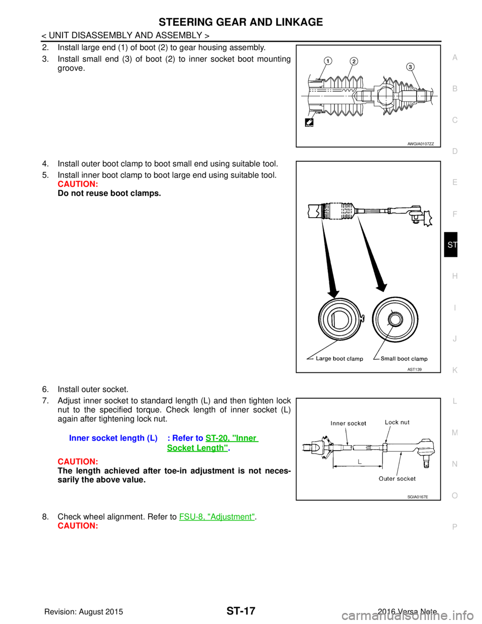
2. Install large end (1) of boot (2) to gear housing assembly.
3. Install small end (3) of boot (2) to inner socket boot mounting groove.
4. Install outer boot clamp to boot small end using suitable tool.
5. Install inner boot clamp to boot large end using suitable tool. CAUTION:
Do not reuse boot clamps.
6. Install outer socket.
7. Adjust inner socket to standard length (L) and then tighten lock nut to the specified torque. Check length of inner socket (L)
again after tightening lock nut.
CAUTION:
The length achieved after toe-in adjustment is not neces-
sarily the above value.
8. Check wheel alignment. Refer to FSU-8, "
Adjustment".
CAUTION:
AWGIA0107ZZ
AST139
Inner socket length (L) : Refer to ST-20, "Inner
Socket Length".
SGIA0167E
Revision: August 2015 2016 Versa Note
cardiagn.com
Page 3239 of 3641

ST-18
< UNIT DISASSEMBLY AND ASSEMBLY >
STEERING GEAR AND LINKAGE
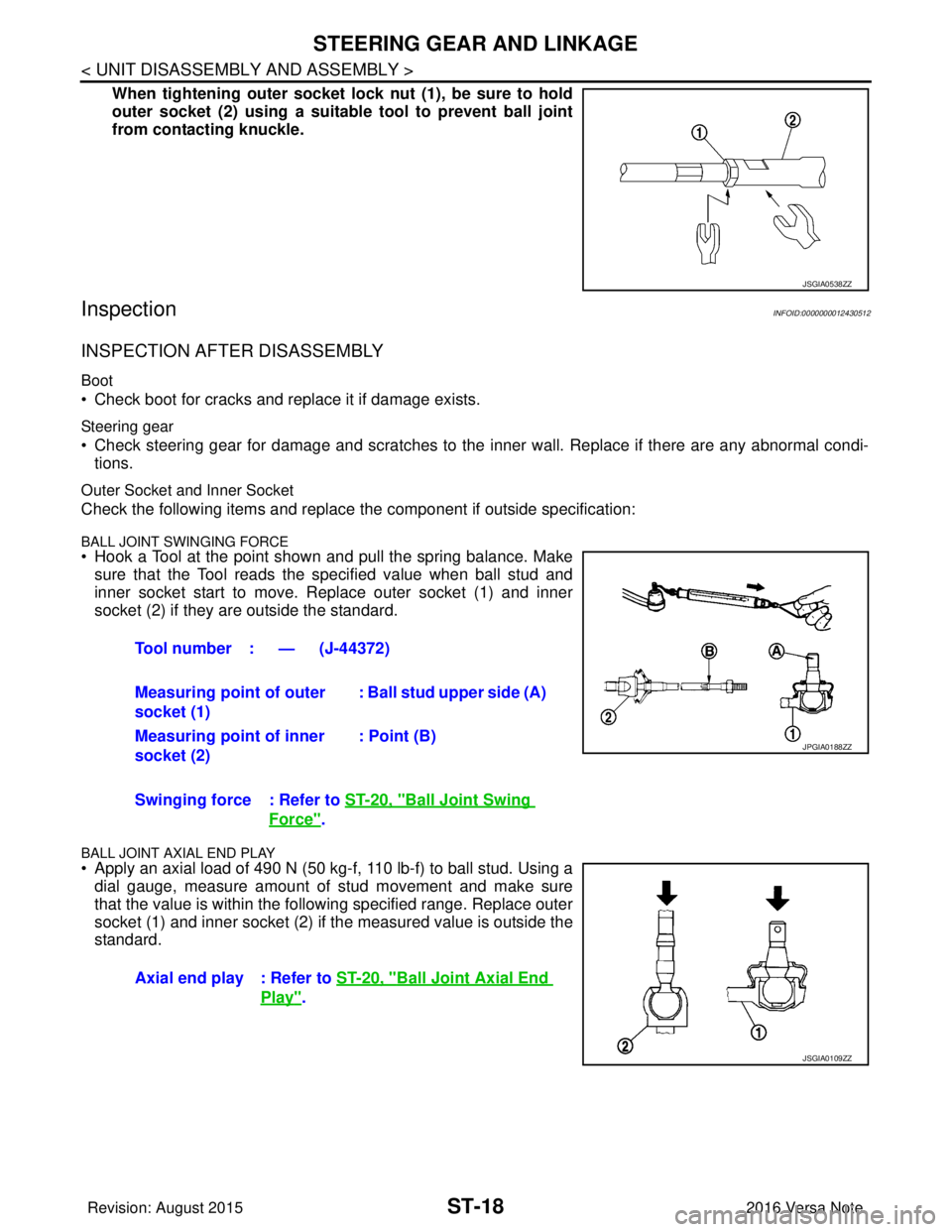
When tightening outer socket lock nut (1), be sure to hold
outer socket (2) using a suitable tool to prevent ball joint
from contacting knuckle.
InspectionINFOID:0000000012430512
INSPECTION AFTER DISASSEMBLY
Boot
• Check boot for cracks and replace it if damage exists.
Steering gear
• Check steering gear for damage and scratches to the inner wall. Replace if there are any abnormal condi- tions.
Outer Socket and Inner Socket
Check the following items and replace the component if outside specification:
BALL JOINT SWINGING FORCE• Hook a Tool at the point shown and pull the spring balance. Make
sure that the Tool reads the specified value when ball stud and
inner socket start to move. Replace outer socket (1) and inner
socket (2) if they are outside the standard.
BALL JOINT AXIAL END PLAY
• Apply an axial load of 490 N (50 kg-f, 110 lb-f) to ball stud. Using adial gauge, measure amount of stud movement and make sure
that the value is within the following specified range. Replace outer
socket (1) and inner socket (2) if the measured value is outside the
standard.
JSGIA0538ZZ
Tool number : — (J-44372)
Measuring point of outer
socket (1) : Ball stud upper side (A)
Measuring point of inner
socket (2) : Point (B)
Swinging force : Refer to ST-20, "
Ball Joint Swing
Force".
Axial end play : Refer to ST-20, "
Ball Joint Axial End
Play".
JPGIA0188ZZ
JSGIA0109ZZ
Revision: August 2015 2016 Versa Note
cardiagn.com
Page 3240 of 3641

SERVICE DATA AND SPECIFICATIONS (SDS)ST-19
< SERVICE DATA AND SPECIFICATIONS (SDS)
C
DE
F
H I
J
K L
M A
B
ST
N
O P
SERVICE DATA AND SPECIFICATIONS (SDS)
SERVICE DATA AND SPECIFICATIONS (SDS)
General SpecificationsINFOID:0000000012430513
Steering Wheel Axial End Play and PlayINFOID:0000000012430514
Unit: mm (in)
Steering Wheel Turning ForceINFOID:0000000012430515
Unit: N (kg-f, lb-f)
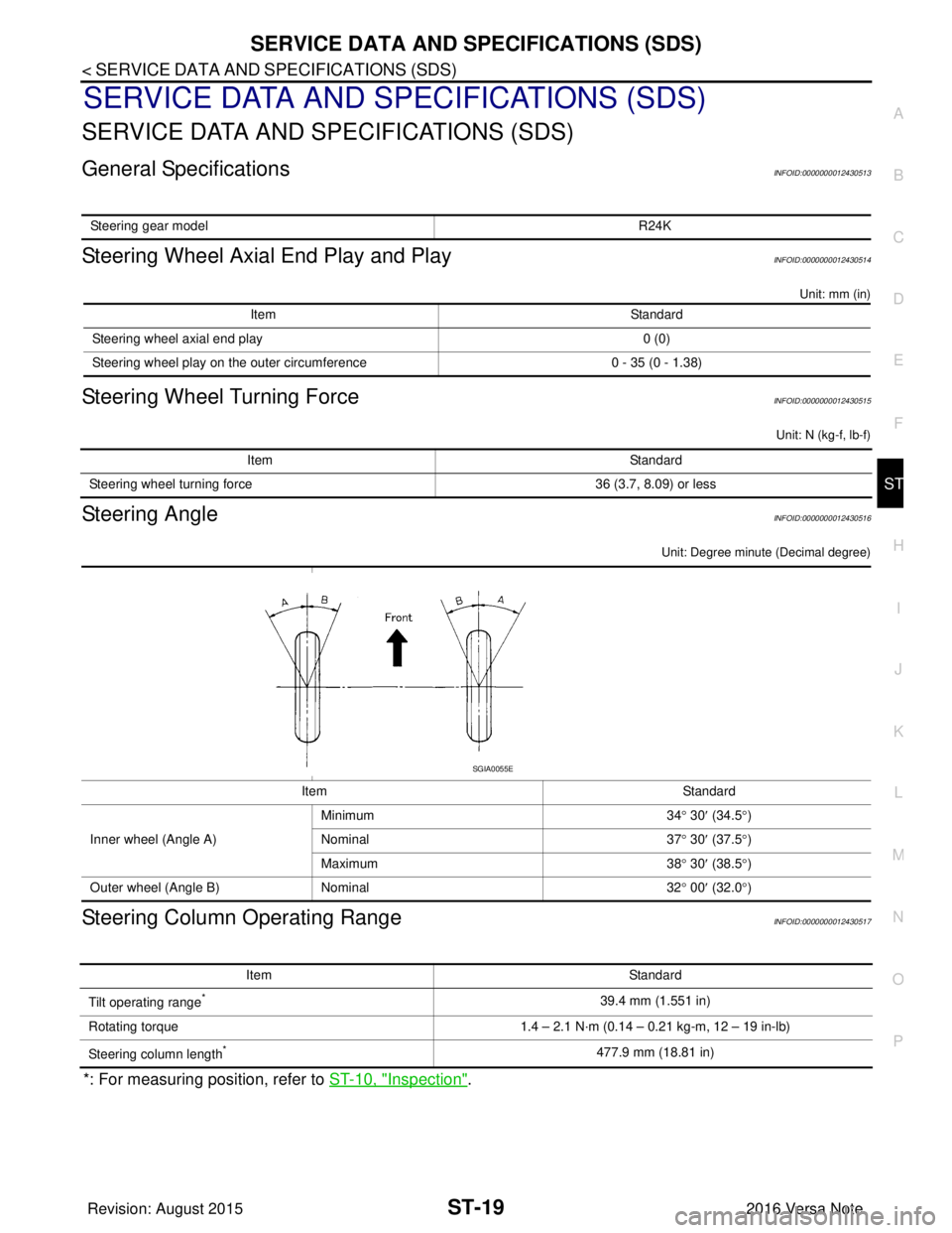
Steering AngleINFOID:0000000012430516
Unit: Degree minute (Decimal degree)
Steering Column Operating RangeINFOID:0000000012430517
*: For measuring position, refer to ST-10, "Inspection".
Steering gear model R24K
ItemStandard
Steering wheel axial end play 0 (0)
Steering wheel play on the outer circumference 0 - 35 (0 - 1.38)
ItemStandard
Steering wheel turning force 36 (3.7, 8.09) or less
ItemStandard
Inner wheel (Angle A) Minimum
34° 30 ′ (34.5° )
Nominal 37° 30 ′ (37.5° )
Maximum 38° 30 ′ (38.5° )
Outer wheel (Angle B) Nominal 32° 00 ′ (32.0° )
SGIA0055E
Item Standard
Tilt operating range
*39.4 mm (1.551 in)
Rotating torque 1.4 – 2.1 N·m (0.14 – 0.21 kg-m, 12 – 19 in-lb)
Steering column length
*477.9 mm (18.81 in)
Revision: August 2015 2016 Versa Note
cardiagn.com
Page 3266 of 3641
![NISSAN NOTE 2016 Service Repair Manual TRANSAXLE ASSEMBLYTM-25
< UNIT REMOVAL AND INSTALLATION > [5MT: RS5F91R]
C
EF
G H
I
J
K L
M A
B
TM
N
O P
• Do not reuse self-tapping bolt.
• Tighten transaxle assembly bolts to the specified torqu NISSAN NOTE 2016 Service Repair Manual TRANSAXLE ASSEMBLYTM-25
< UNIT REMOVAL AND INSTALLATION > [5MT: RS5F91R]
C
EF
G H
I
J
K L
M A
B
TM
N
O P
• Do not reuse self-tapping bolt.
• Tighten transaxle assembly bolts to the specified torqu](/manual-img/5/57363/w960_57363-3265.png)
TRANSAXLE ASSEMBLYTM-25
< UNIT REMOVAL AND INSTALLATION > [5MT: RS5F91R]
C
EF
G H
I
J
K L
M A
B
TM
N
O P
• Do not reuse self-tapping bolt.
• Tighten transaxle assembly bolts to the specified torque. The illus- tration is the view from the engine.
InspectionINFOID:0000000012430963
INSPECTION AFTER INSTALLATION
• Check the operation of the control linkage. Refer to TM-21, "Inspection".
• Before starting engine, check oil/fluid levels incl uding engine coolant and engine oil. If less than required
quantity, fill to the specified level. Refer to MA-11, "
Fluids and Lubricants".
• Use procedure below to check for fuel leaks.
• Turn ignition switch ON (with engine stopped). With fuel pressure applied to fuel piping, check for fuel leaks at connection points.
• Start engine. With engine speed increased, check again for fuel leaks at connection points.
• Run engine to check for unusual noise and vibration. NOTE:
If hydraulic pressure inside timing chain tensioner drops after removal and installation, slack in the guide
may generate a pounding noise during and just after engine start. However, this is normal. Noise will stop
after hydraulic pressure rises.
• Warm up engine thoroughly to make sure there is no lea ks of fuel, exhaust gas, or any oils/fluids including
engine oil and engine coolant.
• Bleed air from passages in lines and hoses, such as in cooling system.
• After cooling down engine, again check oil/fluid levels including engine oil and engine coolant. Refill to spec-
ified level, if necessary.
• Summary of the inspection items:
*Power steering fluid, brake fluid, etc.
Bolt symbol
ABC D
Insertion direction Transaxle to
engine Engine to transaxle
Quantity 2321
Bolt length
() mm (in) 55 (2.17)
49 (1.93) 69 (2.72)
Tightening torque
N·m (kg-m, ft-lb) 48.0 (4.9, 35)
JPDIC0813ZZ
Item
Before starting engine Engine runningAfter engine stopped
Engine coolant LevelLeaks Level
Engine oil LevelLeaks Level
Transmission/
transaxle fluid CVT Models
LeaksLevel/Leaks Leaks
M/T Models Level/Leaks LeaksLevel/Leaks
Other oils and fluids* LevelLeaks Level
Fuel LeaksLeaks Leaks
Exhaust gas —Leaks —
Revision: August 2015 2016 Versa Note
cardiagn.com
Page 3329 of 3641
![NISSAN NOTE 2016 Service Repair Manual TM-88
< SYSTEM DESCRIPTION >[CVT: RE0F11A]
SYSTEM
Provides idle neutral control when st
op/start operation is not performed.
Idle Neutral Control Start Condition
Idle neutral control is started when NISSAN NOTE 2016 Service Repair Manual TM-88
< SYSTEM DESCRIPTION >[CVT: RE0F11A]
SYSTEM
Provides idle neutral control when st
op/start operation is not performed.
Idle Neutral Control Start Condition
Idle neutral control is started when](/manual-img/5/57363/w960_57363-3328.png)
TM-88
< SYSTEM DESCRIPTION >[CVT: RE0F11A]
SYSTEM
Provides idle neutral control when st
op/start operation is not performed.
Idle Neutral Control Start Condition
Idle neutral control is started when all of the following conditions are fulfilled. However, during idle neutral con-
trol, idle neutral control is stopped when any of the following conditions is not met or idle neutral control contin-
ues 30 seconds.
NOTE:
Stops or prohibits the idle neutral control when the TC M and ECM detect that the vehicle is in one of the fol-
lowing conditions.
• Engine coolant temperature and CVT fluid temperature are the specified temperature or more, or the speci-
fied temperature or less.
• When a transaxle malfunction occurs.
• When the vehicle detects DTC and is in the fail-safe mode.
• When idle speed increases due to heavy electric load*. *: When any one of rear window defogger switch, A/C s witch, headlamp, fog lamp is turned ON. In addition,
when the steering wheel is operated.
JPDIA1215GB
Driving environment : Flat road or road with mild gradient
Selector lever position : “D” position
Vehicle speed : 0 km/h (0 MPH)
Accelerator pedal position : 0.0/8
Brake pedal : Depressed
Engine speed : Idle speed
Turn signal lamp/hazard signal lamp : Not activated
Revision: August 2015 2016 Versa Note
cardiagn.com
Page 3478 of 3641
![NISSAN NOTE 2016 Service Repair Manual KEY INTERLOCK CABLETM-237
< REMOVAL AND INSTALLATION > [CVT: RE0F11A]
C
EF
G H
I
J
K L
M A
B
TM
N
O P
KEY INTERLOCK CABLE
Exploded ViewINFOID:0000000012431182
Removal and InstallationINFOID:0000000012 NISSAN NOTE 2016 Service Repair Manual KEY INTERLOCK CABLETM-237
< REMOVAL AND INSTALLATION > [CVT: RE0F11A]
C
EF
G H
I
J
K L
M A
B
TM
N
O P
KEY INTERLOCK CABLE
Exploded ViewINFOID:0000000012431182
Removal and InstallationINFOID:0000000012](/manual-img/5/57363/w960_57363-3477.png)
KEY INTERLOCK CABLETM-237
< REMOVAL AND INSTALLATION > [CVT: RE0F11A]
C
EF
G H
I
J
K L
M A
B
TM
N
O P
KEY INTERLOCK CABLE
Exploded ViewINFOID:0000000012431182
Removal and InstallationINFOID:0000000012431183
REMOVAL
CAUTION:
Always apply the parking brake before pe rforming removal and installation.
1. Move the shift selector to the “N” position.
2. Remove the shift selector handle. Refer to TM-232, "
Disassembly and Assembly".
3. Remove the instrumental lower panel LH. Refer to IP-24, "
Removal and Installation".
4. Remove steering column covers. Refer to IP-17, "
Removal and Installation".
5. Remove the center console. Refer to IP-18, "
Removal and Installation".
6. Move the shift selector to the “P” position.
7. Press the pawls (B) of the key interlock cable slider (A) while sliding it in the direction of the casing cap (C), and separate the
adjusting holder (D) and slider.
8. Remove the key interlock cable from the shift selector assembly.
1. Shift selector assembly 2. Key interlock cable A: Steering lock unit
B: Lock plate C: Clip
ALDIA0262ZZ
(E) :Key interlock rod
JSDIA1797ZZ
Revision: August 2015 2016 Versa Note
cardiagn.com
Page 3479 of 3641
![NISSAN NOTE 2016 Service Repair Manual TM-238
< REMOVAL AND INSTALLATION >[CVT: RE0F11A]
KEY INTERLOCK CABLE
9. Lift lock plate (A) in the direction of the arrow ( C) and remove
in the direction of the arrow ( D).
10. Remove the key interl NISSAN NOTE 2016 Service Repair Manual TM-238
< REMOVAL AND INSTALLATION >[CVT: RE0F11A]
KEY INTERLOCK CABLE
9. Lift lock plate (A) in the direction of the arrow ( C) and remove
in the direction of the arrow ( D).
10. Remove the key interl](/manual-img/5/57363/w960_57363-3478.png)
TM-238
< REMOVAL AND INSTALLATION >[CVT: RE0F11A]
KEY INTERLOCK CABLE
9. Lift lock plate (A) in the direction of the arrow ( C) and remove
in the direction of the arrow ( D).
10. Remove the key interlock cable from the steering lock unit.
11. Disengage the clips and remove the key interlock cable from the vehicle.
INSTALLATION
Installation is in the reverse order of removal.
• Temporarily install the adjust holder (A) to the key interlock rod (B).
• Install the casing cap (C) to the cable bracket (D) on the shift
selector assembly.
CAUTION:
• Do not bend or twist key interlock cable excessively wheninstalling.
• After installing key interlock cable to cable bracket (D) on shift selector assembly, make sure casing caps (C) is firmly
secured in cable bracket (D) on shift selector assembly.
• If casing cap (C) is loose [less than 39.2 N (4.0 kg, 8.8 lb) removing force], replace key interlock cable.
• Slide the slider (A) toward the key interlock rod (D) while pressing the pull lock (B) down to securely connect the adjust holder (C)
with the key interlock rod (D).
CAUTION:
• Do not press tabs when holding slider (A).
• Do not apply any side to side force to key interlock rod (D)
when sliding slider (A).
InspectionINFOID:0000000012431184
INSPECTION AFTER INSTALLATION
• Check the CVT operation. If a malfunction is found, adjust the CVT position. Refer to TM-232, "Inspection".
• Make sure the key can be removed only when the shift selector is in the “P” position.
• Make sure the ignition switch will not turn to LOCK pos ition when the shift selector is not in the “P” position.
(1) :Key interlock cable
(B) :Steering lock unit
JSDIA1798ZZ
JSDIA1799ZZ
JSDIA1800ZZ
Revision: August 2015 2016 Versa Note
cardiagn.com
Page 3503 of 3641
![NISSAN NOTE 2016 Service Repair Manual TM-262
< UNIT REMOVAL AND INSTALLATION >[CVT: RE0F11A]
TRANSMISSION ASSEMBLY
INSPECTION AFTER INSTALLATION
Check the following items:
• For CVT position, refer to
TM-232, "
Inspection".
• Before NISSAN NOTE 2016 Service Repair Manual TM-262
< UNIT REMOVAL AND INSTALLATION >[CVT: RE0F11A]
TRANSMISSION ASSEMBLY
INSPECTION AFTER INSTALLATION
Check the following items:
• For CVT position, refer to
TM-232, "
Inspection".
• Before](/manual-img/5/57363/w960_57363-3502.png)
TM-262
< UNIT REMOVAL AND INSTALLATION >[CVT: RE0F11A]
TRANSMISSION ASSEMBLY
INSPECTION AFTER INSTALLATION
Check the following items:
• For CVT position, refer to
TM-232, "
Inspection".
• Before starting engine, check oil/fluid levels incl uding engine coolant and engine oil. If less than required
quantity, fill to the specified level. Refer to MA-11, "
Fluids and Lubricants".
• Use procedure below to check for fuel leakage.
• Turn ignition switch ON (with engine stopped). With fuel pressure applied to fuel piping, check for fuel leak-
age at connection points.
• Start engine. With engine speed increased, che ck again for fuel leakage at connection points.
• Run engine to check for unusual noise and vibration. NOTE:
If hydraulic pressure inside timing chain tensioner drops after removal and installation, slack in the guide
may generate a pounding noise during and just after engine start. However, this is normal. Noise will stop
after hydraulic pressure rises.
• Warm up engine thoroughly to make sure there is no leakage of fuel, exhaust gas, or any oils/fluids including engine oil and engine coolant.
• Bleed air from passages in lines and hoses, such as in cooling system.
• After cooling down engine, again check oil/fluid levels including engine oil and engine coolant. Refill to spec- ified level, if necessary.
• Summary of the inspection items:
*Power steering fluid, brake fluid, etc.
ADJUSTMENT AFTER INSTALLATION
• Adjust the CVT fluid level. TM-229, "Adjustment".
• Perform "ADDITIONAL SERVICE WHEN REPL ACING TRANSAXLE ASSEMBLY". Refer to TM-127,
"Description".
ItemBefore starting engine Engine runningAfter engine stopped
Engine coolant LevelLeakage Level
Engine oil LevelLeakage Level
Transmission/
transaxle fluid A/T and CVT Models
LeakageLevel/Leakage Leakage
M/T Models Level/Leakage LeakageLevel/Leakage
Other oils and fluids* LevelLeakage Level
Fuel LeakageLeakageLeakage
Exhaust gas —Leakage —
Revision: August 2015 2016 Versa Note
cardiagn.com