2016 NISSAN NOTE transmission oil
[x] Cancel search: transmission oilPage 2324 of 3641

PERIODIC MAINTENANCEMA-9
< PERIODIC MAINTENANCE >
C
DE
F
G H
I
J
K L
M B
MA
N
O A
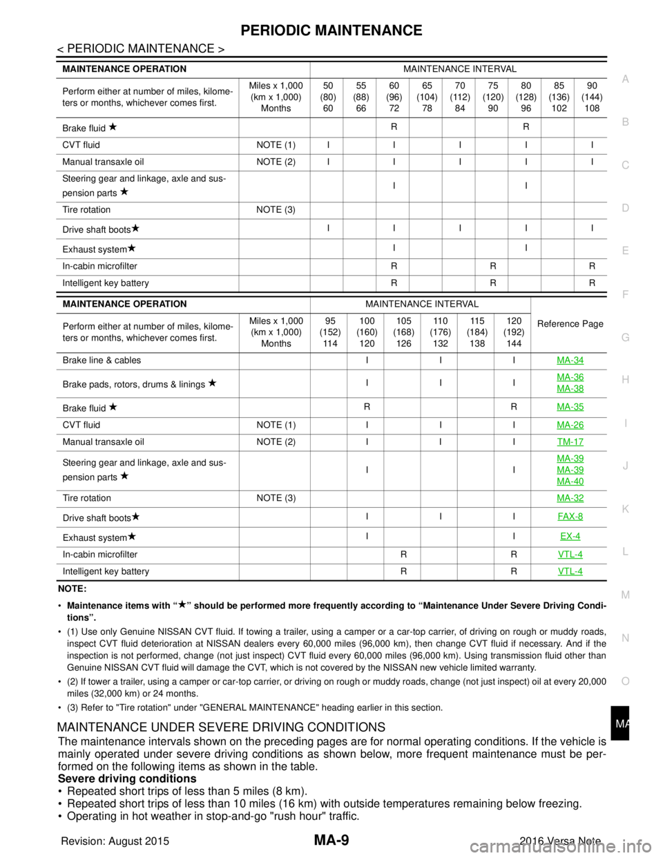
NOTE:
•
Maintenance items with “ ” shoul d be performed more frequently according to “Maintenance Under Severe Driving Condi-
tions”.
• (1) Use only Genuine NISSAN CVT fluid. If towing a trailer, using a camper or a car-top carrier, of driving on rough or muddy roads,
inspect CVT fluid deterioration at NISSAN dealers every 60,000 miles (96,000 km), then change CVT fluid if necessary. And if th e
inspection is not performed, change (not just inspect) CVT fluid every 60,000 miles (96,000 km). Using transmission fluid other than
Genuine NISSAN CVT fluid will damage the CVT, which is not covered by the NISSAN new vehicle limited warranty.
• (2) If tower a trailer, using a camper or car-top carrier, or driving on rough or muddy roads, change (not just inspect) oil a t every 20,000
miles (32,000 km) or 24 months.
• (3) Refer to "Tire rotation" under "GENERAL MAINTENANCE" heading earlier in this section.
MAINTENANCE UNDER SEVERE DRIVING CONDITIONS
The maintenance intervals shown on the preceding pages are for normal operating conditions. If the vehicle is
mainly operated under severe driving conditions as shown below, more frequent maintenance must be per-
formed on the following items as shown in the table.
Severe driving conditions
• Repeated short trips of less than 5 miles (8 km).
• Repeated short trips of less than 10 miles (16 km) wi th outside temperatures remaining below freezing.
• Operating in hot weather in stop-and-go "rush hour" traffic.
Brake fluid RR
C VT flu id NO TE (1)IIIII
M anu al t ra nsa xle o il NO TE (2)IIIII
Steering gear and linkage, axle and sus-
pension parts II
Tire rotation NOTE (3)
Drive shaft boots IIIII
Exhaust system II
In-cabin microfilter RRR
Intelligent key battery RRR
MAINTENANCE OPERATION MAINTENANCE INTERVAL
Reference Page
Perform either at number of miles, kilome-
ters or months, whichever comes first. Miles x 1,000
(km x 1,000) Months 95
(152) 11 4 100
(160) 120 105
(168) 126 11 0
(176) 132 11 5
(184) 138 120
(192) 144
Brake line & cables IIIMA-34
Brake pads, rotors, drums & linings IIIMA-36MA-38
Brake fluid
RR
MA-35
CVT fluid NOTE (1)IIIMA-26
Manual transaxle oil NOTE (2)IIITM-17
Steering gear and linkage, axle and sus-
pension parts IIMA-39MA-39
MA-40
Tire rotation
NOTE (3) MA-32
Drive shaft boots III
FAX-8
Exhaust system II
EX-4
In-cabin microfilter RRVTL-4
Intelligent key battery RRVTL-4
MAINTENANCE OPERATION MAINTENANCE INTERVAL
Perform either at number of miles, kilome-
ters or months, whichever comes first. Miles x 1,000
(km x 1,000)
Months 50
(80)
60 55
(88)
66 60
(96)
72 65
(104)
78 70
(112)
84 75
(120)
90 80
(128)
96 85
(136)
102 90
(144)
108
Revision: August 2015 2016 Versa Note
cardiagn.com
Page 2326 of 3641

RECOMMENDED FLUIDS AND LUBRICANTSMA-11
< PERIODIC MAINTENANCE >
C
DE
F
G H
I
J
K L
M B
MA
N
O A
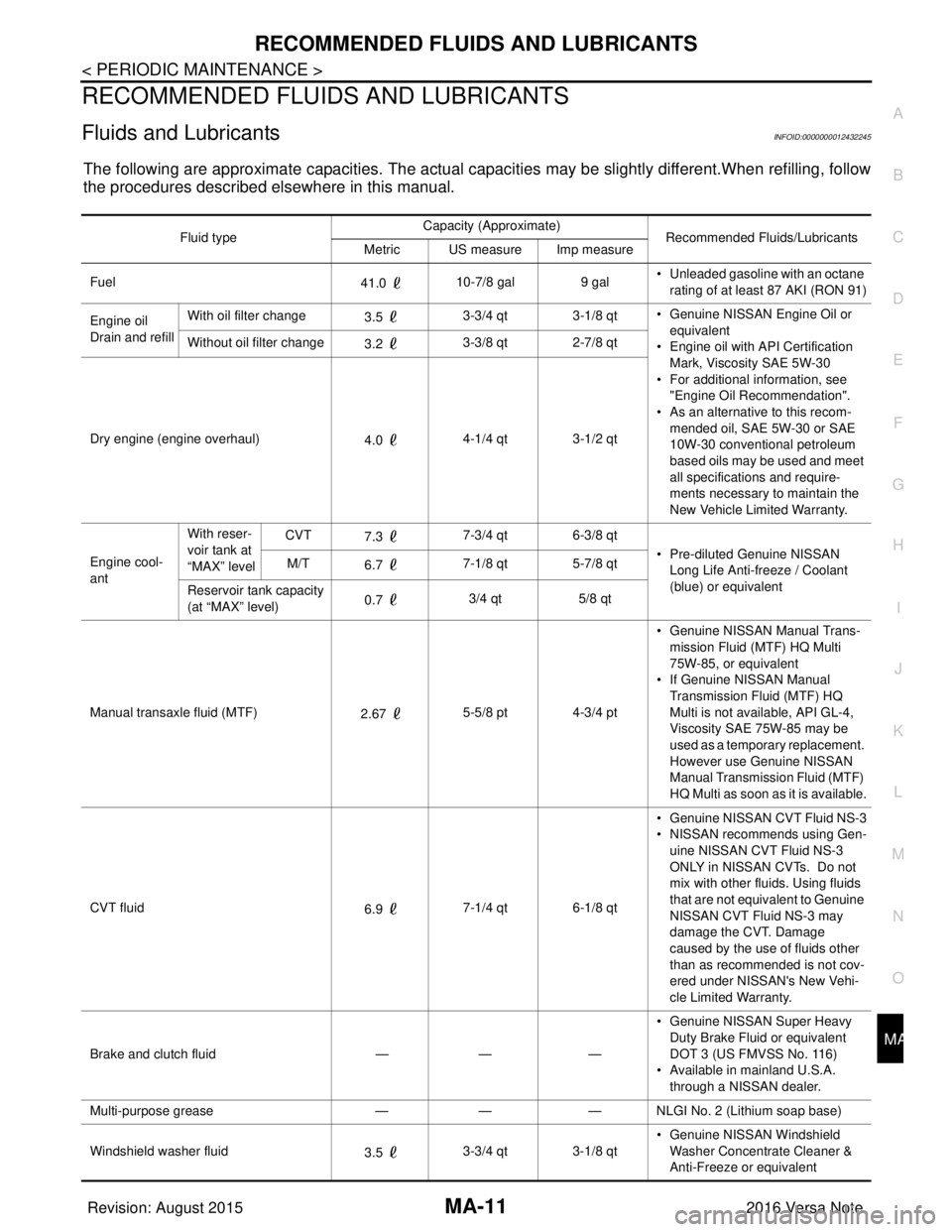
RECOMMENDED FLUIDS AND LUBRICANTS
Fluids and LubricantsINFOID:0000000012432245
The following are approximate capacities. The actual capa
cities may be slightly different.When refilling, follow
the procedures described elsewhere in this manual.
Fluid type Capacity (Approximate)
Recommended Fluids/Lubricants
Metric US measure Imp measure
Fuel 41.0 10-7/8 gal
9 gal• Unleaded gasoline with an octane
rating of at least 87 AKI (RON 91)
Engine oil
Drain and refill With oil filter change
3.5 3-3/4 qt 3-1/8 qt
• Genuine NISSAN Engine Oil or
equivalent
• Engine oil with API Certification
Mark, Viscosity SAE 5W-30
• For additional information, see "Engine Oil Recommendation".
• As an alternative to this recom-
mended oil, SAE 5W-30 or SAE
10W-30 conventional petroleum
based oils may be used and meet
all specifications and require-
ments necessary to maintain the
New Vehicle Limited Warranty.
Without oil filter change
3.2 3-3/8 qt 2-7/8 qt
Dry engine (engine overhaul) 4.0 4-1/4 qt 3-1/2 qt
Engine cool-
ant With reser-
voir tank at
“MAX” level
CVT
7.3 7-3/4 qt 6-3/8 qt
• Pre-diluted Genuine NISSAN Long Life Anti-freeze / Coolant
(blue) or equivalent
M/T
6.7 7-1/8 qt 5-7/8 qt
Reservoir tank capacity
(at “MAX” level) 0.7
3/4 qt
5/8 qt
Manual transaxle fluid (MTF) 2.67 5-5/8 pt 4-3/4 pt • Genuine NISSAN
Manual Trans-
mission Fluid (MTF) HQ Multi
75W-85, or equivalent
• If Genuine NISSAN Manual
Transmission Fluid (MTF) HQ
Multi is not available, API GL-4,
Viscosity SAE 75W-85 may be
used as a temporary replacement.
However use Genuine NISSAN
Manual Transmission Fluid (MTF)
HQ Multi as soon as it is available.
CVT fluid 6.9 7-1/4 qt 6-1/8 qt • Genuine NISSAN CVT Fluid NS-3
• NISSAN recommends using Gen-
uine NISSAN CVT Fluid NS-3
ONLY in NISSAN CVTs. Do not
mix with other fluids. Using fluids
that are not equivalent to Genuine
NISSAN CVT Fluid NS-3 may
damage the CVT. Damage
caused by the use of fluids other
than as recommended is not cov-
ered under NISSAN's New Vehi-
cle Limited Warranty.
Brake and clutch fluid —— —• Genuine NISSAN Super Heavy
Duty Brake Fluid or equivalent
DOT 3 (US FMVSS No. 116)
• Available in mainland U.S.A.
through a NISSAN dealer.
Multi-purpose grease —— — NLGI No. 2 (Lithium soap base)
Windshield washer fluid 3.5 3-3/4 qt 3-1/8 qt • Genuine NISSAN Windshield
Washer Concentrate Cleaner &
Anti-Freeze or equivalent
Revision: August 2015 2016 Versa Note
cardiagn.com
Page 2341 of 3641

MA-26
< PERIODIC MAINTENANCE >
CHASSIS AND BODY MAINTENANCE
CHASSIS AND BODY MAINTENANCE
EXHAUST SYSTEM
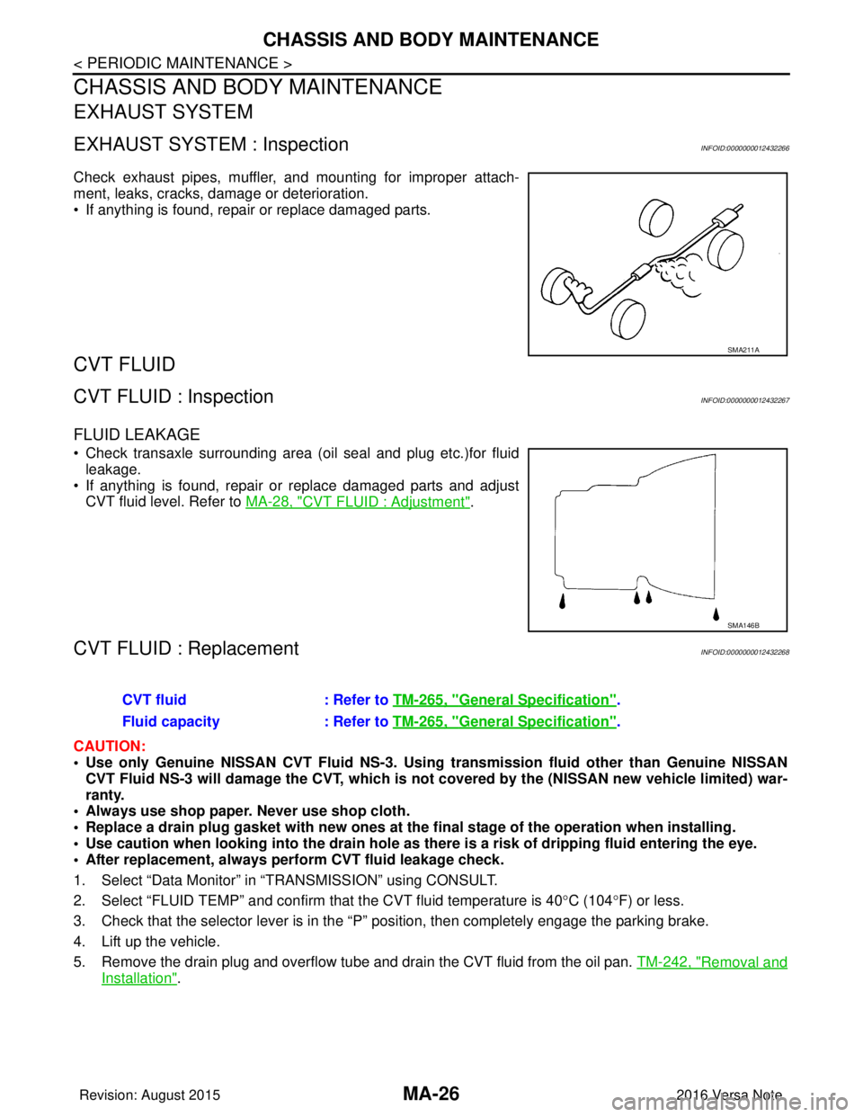
EXHAUST SYSTEM : InspectionINFOID:0000000012432266
Check exhaust pipes, muffler, and mounting for improper attach-
ment, leaks, cracks, damage or deterioration.
• If anything is found, repair or replace damaged parts.
CVT FLUID
CVT FLUID : InspectionINFOID:0000000012432267
FLUID LEAKAGE
• Check transaxle surrounding area (oil seal and plug etc.)for fluidleakage.
• If anything is found, repair or replace damaged parts and adjust CVT fluid level. Refer to MA-28, "
CVT FLUID : Adjustment".
CVT FLUID : ReplacementINFOID:0000000012432268
CAUTION:
• Use only Genuine NISSAN CVT Fluid NS-3. Using transmission fluid other than Genuine NISSAN
CVT Fluid NS-3 will damage the CVT, which is not covered by the (NISSAN new vehicle limited) war-
ranty.
• Always use shop paper. Never use shop cloth.
• Replace a drain plug gasket with new ones at the final stage of the operation when installing.
• Use caution when looking into the drain hole as th ere is a risk of dripping fluid entering the eye.
• After replacement, always perform CVT fluid leakage check.
1. Select “Data Monitor” in “T RANSMISSION” using CONSULT.
2. Select “FLUID TEMP” and confirm t hat the CVT fluid temperature is 40°C (104° F) or less.
3. Check that the selector lever is in the “P ” position, then completely engage the parking brake.
4. Lift up the vehicle.
5. Remove the drain plug and overflow tube and drain the CVT fluid from the oil pan. TM-242, "
Removal and
Installation".
SMA211A
SMA146B
CVT fluid: Refer to TM-265, "General Specification".
Fluid capacity : Refer to TM-265, "
General Specification".
Revision: August 2015 2016 Versa Note
cardiagn.com
Page 2343 of 3641

MA-28
< PERIODIC MAINTENANCE >
CHASSIS AND BODY MAINTENANCE
29. When the flow of CVT fluid slows to a drip, tighten the drain plug to the specified torque. TM-242,
"Removal and Installation".
CAUTION:
Never reuse drain plug gasket.
30. Lift down the vehicle.
31. Select “Work Support” in “TRANSMISSION” using CONSULT.
32. Select “CONFORM CVTF DETERIORTN”.
33. Select “Erase”.
34. Stop the engine.
CVT FLUID : AdjustmentINFOID:0000000012432269
CAUTION:
• Use only Genuine NISSAN CVT Fluid NS-3. Using transmission fluid other than Genuine NISSAN
CVT Fluid NS-3 will damage the CVT, which is not covered by the (NISSAN new vehicle limited) war-
ranty.
• During adjustment of the CVT fluid level, check CO NSULT so that the oil temperature may be main-
tained from 35 to 45 °C (95 to 113 °F).
• Use caution when looking into the drain hole as th ere is a risk of dripping fluid entering the eye.
1. Check that the selector lever is in the “P ” position, then completely engage the parking brake.
2. Start the engine.
3. Adjust the CVT fluid temperature to be approximately 40 °C (104° F).
NOTE:
The CVT fluid is largely affected by temperature. Therefore be sure to use CONSULT and check the
“FLUID TEMP” under “TRANSMISSION” in “Data Monitor” while adjusting.
4. While depressing the brake pedal, shift the selector lever to the entire position from “P” to “L”, and shift it to the “P” position.
NOTE:
Hold the lever at each position for 5 seconds.
5. Lift up the vehicle.
6. Check that there is no CVT fluid leakage.
7. Remove the drain plug. Refer to TM-242, "
Removal and Installation".
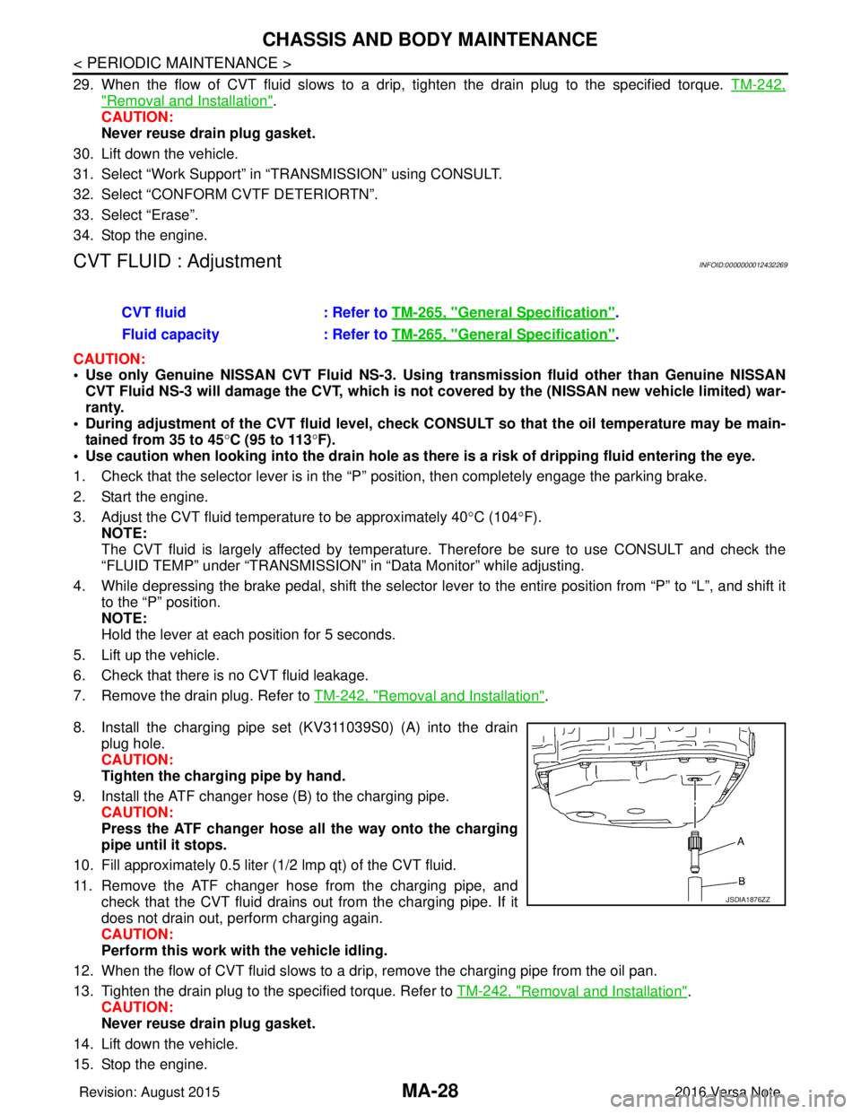
8. Install the charging pipe set (KV311039S0) (A) into the drain plug hole.
CAUTION:
Tighten the charging pipe by hand.
9. Install the ATF changer hose (B) to the charging pipe. CAUTION:
Press the ATF changer hose all the way onto the charging
pipe until it stops.
10. Fill approximately 0.5 liter (1/2 lmp qt) of the CVT fluid.
11. Remove the ATF changer hose from the charging pipe, and check that the CVT fluid drains out from the charging pipe. If it
does not drain out, perform charging again.
CAUTION:
Perform this work with the vehicle idling.
12. When the flow of CVT fluid slows to a drip, remove the charging pipe from the oil pan.
13. Tighten the drain plug to the specified torque. Refer to TM-242, "
Removal and Installation".
CAUTION:
Never reuse drain plug gasket.
14. Lift down the vehicle.
15. Stop the engine. CVT fluid
: Refer to TM-265, "
General Specification".
Fluid capacity : Refer to TM-265, "
General Specification".
JSDIA1876ZZ
Revision: August 2015 2016 Versa Note
cardiagn.com
Page 2519 of 3641
![NISSAN NOTE 2016 Service Repair Manual PCS-16
< ECU DIAGNOSIS INFORMATION >[IPDM E/R]
IPDM E/R (INTELLIGENT POWER DI
STRIBUTION MODULE ENGINE ROOM)
7PCooling fan power sup-
ply (LOW) OutputON
or
START Cooling fan OFF
0V
Cooling fan LO Batt NISSAN NOTE 2016 Service Repair Manual PCS-16
< ECU DIAGNOSIS INFORMATION >[IPDM E/R]
IPDM E/R (INTELLIGENT POWER DI
STRIBUTION MODULE ENGINE ROOM)
7PCooling fan power sup-
ply (LOW) OutputON
or
START Cooling fan OFF
0V
Cooling fan LO Batt](/manual-img/5/57363/w960_57363-2518.png)
PCS-16
< ECU DIAGNOSIS INFORMATION >[IPDM E/R]
IPDM E/R (INTELLIGENT POWER DI
STRIBUTION MODULE ENGINE ROOM)
7PCooling fan power sup-
ply (LOW) OutputON
or
START Cooling fan OFF
0V
Cooling fan LO Battery voltage
Cooling fan MID 4 – 8 V
Cooling fan HI Battery voltage
8 G Battery power supply Input OFF —Battery voltage
9BR Fuel pump power sup-
ply
OutputON
RUN Approximately 1 second af-
ter turning the ignition
switch ON
Battery voltage
ON Approximately 1 second af-
ter turning the ignition
switch ON 0V
10
2L Ignition switch power
supply (ON or START)
InputOFF
0V
ON or
START Battery voltage
11 G ECM relay power supply Output OFF
More than a few seconds
after turning ignition switch
OFF 0V
ON
OFF For a few seconds after
turning ignition switch OFF
Battery voltage
13
3R1
LG2Starter relay coil power
supply Input ONClutch pedal depressed
0V
Clutch pedal released Battery voltage
14 L Headlamp LOW (LH)
power supply OutputLighting switch OFF
0V
Lighting switch 2ND Battery voltage
15
1, 3LG Starter relay coil power
supply Input 0V
Battery voltage
16 P Headlamp LOW (RH)
power supply OutputLighting switch OFF
0V
Lighting switch 2ND Battery voltage
17 LG Front wiper motor LOW
power supply Output ONFront wiper switch OFF
0V
Front wiper switch LO Battery voltage
18 GR Front wiper motor HIGH
power supply
Output ONFront wiper switch OFF
0V
Front wiper switch HI Battery voltage
19 B Ground — —— —
20 BR ABS actuator and elec-
tric unit (control unit)
power supply OutputOFF
— 0V
ON or
START —B
att e ry v olt a ge
21
3G Clutch interlock switch
power supply
OutputOFF
or
ACC 0V
ON Battery voltage
21
4R Transmission range
switch power supply OutputOFF
or
ACC 0V
ON Battery voltage
22 P Illumination power sup-
ply
OutputLighting switch OFF
0V
Lighting switch 1ST Battery voltage
Te r m i n a l
Wire
color Circuit Input/
Output Ignition
switch Condition
Value
Revision: August 2015 2016 Versa Note
cardiagn.com
Page 2636 of 3641

PG
HARNESSPG-49
< WIRING DIAGRAM >
C
DE
F
G H
I
J
K L
B A
O P
N
B3 F1 B/3 : Generator
D4 F28 — : Starter motor
B3 F2 — : Generator D3 F29 B/2 : Fuel injector no. 3 (Rear)
B4 F3 B/1 : A/C compressor D3 F30 B/2 : Fuel injector no. 4 (Rear)
B4 F4 — : Generator D1 F31 B/6 : Mass air flow sensor
B4 F5 — : Engine ground E1 F32 GR/2: Exhaust valve timing control solenoid
valve
E2 F6 GR/2 : Engine coolant temperature sensor F1 F33 W/6 : To E19
D1 F7 B/6 : Electric throttle control actuator B1 F34 GR/3: Ignition coil no.1 (With power
transistor)
E 1 F 8 W / 2 4 : To E 8 C 1 F 3 5 G R / 3: Ignition coil no.2 (With power
transistor)
F2 F9 GR/4 : Battery current sensor C1 F36 GR/3: Ignition coil no.3 (With power
transistor)
G 2 F 1 0 G R / 3 2 : E C M D 2 F 3 7 G R / 3: Ignition coil no.4 (With power
transistor)
G1 F11 BR/48 : ECM C4 F38 B/3 : Engine oil pressure sensor
D1 F12 BR/4 : Air fuel ratio (A/F) sensor 1 G3 F39 — : Fusible link box (Battery)
C3 F14 GR/2 : Knock sensor G3 F40 — : Fusible link box (Battery)
E1 F15 B/3 : Crankshaft position sensor (POS) G4 F41 B/3 : Output speed sensor
D4 F16 — : Engine ground F2 F42 W/12: IPDM E/R (Intelligent power distribution
module engine room)
B3 F17 B/2 : Fuel injector no. 1 (Front) F2 F43 W/12: IPDM E/R (Intelligent power distribution
module engine room)
C3 F18 B/2 : Fuel injector no. 2 (Front) F2 F44 B/48 : TCM (Transmission control module)
C3 F19 B/2 : Fuel injector no. 3 (Front) F4 F46 GR/22 : CVT unit
D3 F20 B/2 : Fuel injector no. 4 (Front) G4 F48 B/3 : Secondary speed sensor
D2 F21 B/3 : Camshaft position sensor G4 F50 B/3 : Primary speed sensor
C 1 F 2 2 G R / 2 : Evap canister purge volume control
solenoid valve F3 F52 B/10 : Transmission range switch
B 3 F 2 3 G R / 2 : Intake valve timing control solenoid
valve
B3 F53 B/2 : Fuel injector no. 1 (Rear)
E4 F24 G/3 : Park/neutral position (PNP) switch C3 F54 B/2 : Fuel injector no. 2 (Rear)
C4 F25 GR/2 : Engine oil temperature sensor G1 F55 GR/12 : To E55
C 3 F 2 6 W / 2 : C o n d e n s e r D 2 F 5 6 B / 3: Exhaust valve timing control position
sensor
D 3 F 2 7 — : S t a r t e r m o t o r D 3 F 5 9 — : E n g i n e g r o u n d
Revision: August 2015 2016 Versa Note
cardiagn.com
Page 3157 of 3641

COMPONENT PARTSSTR-5
< SYSTEM DESCRIPTION >
C
DE
F
G H
I
J
K L
M A
STR
NP
O
STARTING SYSTEM (WITHOUT INTELL
IGENT KEY) : Component Description
INFOID:0000000012432061
STARTING SYSTEM (WITH INTELLIGENT KEY)
No.Component part Description
1. IPDM E/R CPU inside IPDM E/R operates the starter control relay when
the ignition switch is in the start position.
2. Transmission range switch (CVT Models) Supplies power to the starter co
ntrol relay (inside IPDM E/R)
when the selector lever is shifted into the P or N position.
3. Starter motor The starter motor plunger closes and the motor is supplied
with battery power, which in turn cranks the engine, when the
S terminal is supplied with electric power.
4. Clutch interlock switch (M/T Models) Clutch interlock switch supplies power to the coil side of the
starter control relay when the clutch pedal is depressed to
crank the engine.
Revision: August 2015
2016 Versa Note
cardiagn.com
Page 3242 of 3641

TM-1
TRANSMISSION & DRIVELINE
CEF
G H
I
J
K L
M
SECTION TM
A
B
TM
N
O P
CONTENTS
TRANSAXLE & TRANSMISSION
5MT: RS5F91R
PRECAUTION ....... ........................................
7
PRECAUTIONS .............................................. .....7
Precaution for Supplemental Restraint System
(SRS) "AIR BAG" and "SEAT BELT PRE-TEN-
SIONER" ............................................................. ......
7
General Precautions .................................................7
Precaution for Work ..................................................7
Liquid Gasket ............................................................8
PREPARATION ...........................................10
PREPARATION .............................................. ....10
Special Service Tools .......................................... ....10
Commercial Service Tools ......................................12
SYSTEM DESCRIPTION .............................13
STRUCTURE AND OPERATION ................... ....13
Sectional View ..................................................... ....13
System Description .................................................13
DTC/CIRCUIT DIAGNOSIS .........................15
POSITION SWITCH ........................................ ....15
BACK-UP LAMP SWITCH .................................... ....15
BACK-UP LAMP SWITCH : Component Inspec-
tion ..........................................................................
15
PARK/NEUTRAL POSITION (PNP) SWITCH ....... ....15
PARK/NEUTRAL POSITION (PNP) SWITCH :
Component Inspection ............................................
15
SYMPTOM DIAGNOSIS ..............................16
NOISE, VIBRATION AND HARSHNESS
(NVH) TROUBLESHOOTING ........................ ....
16
NVH Troubleshooting Chart ................................ ....16
PERIODIC MAINTENANCE .........................17
GEAR OIL .........................................................17
Inspection ............................................................ ....17
Draining ...................................................................17
Refilling ....................................................................17
REMOVAL AND INSTALLATION ...............18
SIDE OIL SEAL .................................................18
Removal and Installation ..................................... ....18
Inspection ................................................................18
POSITION SWITCH ..........................................19
Removal and Installation .........................................19
Inspection ................................................................19
CONTROL LINKAGE ........................................20
Exploded View ..................................................... ....20
Removal and Installation .........................................20
Inspection ................................................................21
AIR BREATHER HOSE ....................................22
Exploded View .........................................................22
Removal and Installation .........................................22
5TH MAIN GEAR ASSEMBLY .........................23
Removal and Installation .........................................23
Inspection ................................................................23
UNIT REMOVAL AND INSTALLATION ......24
TRANSAXLE ASSEMBLY ................................24
Exploded View ..................................................... ....24
Removal and Installation .........................................24
Inspection ................................................................25
UNIT DISASSEMBLY AND ASSEMBLY ....26
TRANSAXLE ASSEMBLY ................................26
Exploded View ..................................................... ....26
Disassembly ............................................................30
Assembly .................................................................36
Inspection ................................................................44
Revision: August 2015 2016 Versa Note
cardiagn.com