2016 NISSAN NOTE fuel cap release
[x] Cancel search: fuel cap releasePage 1129 of 3641

EC-2
ELECTRIC IGNITION SYSTEM : System De-
scription ............................................................... ...
35
AIR CONDITIONING CUT CONTROL ................... ...36
AIR CONDITIONING CUT CONTROL : System
Diagram ..................................................................
37
AIR CONDITIONING CUT CONTROL : System
Description ..............................................................
37
CAN COMMUNICATION ........................................ ...38
CAN COMMUNICATION : System Description ......38
COOLING FAN CONTROL .................................... ...38
COOLING FAN CONTROL : System Diagram .......38
COOLING FAN CONTROL : System Description ...38
EVAPORATIVE EMISSION SYSTEM .................... ...40
EVAPORATIVE EMISSION SYSTEM : System
Diagram ............................................................... ...
40
EVAPORATIVE EMISSION SYSTEM : System
Description ........................................................... ...
40
INTAKE VALVE TIMING CONTROL ..................... ...41
INTAKE VALVE TIMING CONTROL : System Di-
agram .................................................................. ...
41
INTAKE VALVE TIMING CONTROL : System De-
scription ............................................................... ...
41
EXHAUST VALVE TIMING CONTROL ................. ...42
EXHAUST VALVE TIMING CONTROL : System
Diagram ............................................................... ...
42
EXHAUST VALVE TIMING CONTROL : System
Description ........................................................... ...
42
ENGINE PROTECTION CONTROL AT LOW EN-
GINE OIL PRESSURE ..............................................
43
ENGINE PROTECTION CONTROL AT LOW EN-
GINE OIL PRESSURE : S ystem Diagram ..............
43
ENGINE PROTECTION CONTROL AT LOW EN-
GINE OIL PRESSURE : S ystem Description .........
43
FUEL FILLER CAP WARNING SYSTEM .............. ...44
FUEL FILLER CAP WARNING SYSTEM :
System Diagram ....................................................
44
FUEL FILLER CAP WARNING SYSTEM : System
Description ........................................................... ...
44
AUTOMATIC SPEED CONTROL DEVICE (ASCD) ...45
AUTOMATIC SPEED CONTROL DEVICE (AS-
CD) : System Diagram ............................................
45
AUTOMATIC SPEED CONTROL DEVICE (AS-
CD) : System Description .......................................
45
OPERATION ......................................................47
AUTOMATIC SPEED CONTROL DEVICE (ASCD) ...47
AUTOMATIC SPEED CONTROL DEVICE (AS-
CD) : Switch Name and Function ...........................
47
ON BOARD DIAGNOSTIC (OBD) SYSTEM .....49
Diagnosis Description .......................................... ...49
GST (Generic Scan Tool) .......................................49
DIAGNOSIS SYSTEM (ECM) ............................50
DIAGNOSIS DESCRIPTION .................................. ...50
DIAGNOSIS DESCRIPTION : 1st Trip Detection
Logic and Two Trip Detection Logic ........................
50
DIAGNOSIS DESCRIPTION : DTC and Freeze
Frame Data .......................................................... ...
50
DIAGNOSIS DESCRIPTION : Counter System ......51
DIAGNOSIS DESCRIPTION : Driving Pattern ..... ...54
DIAGNOSIS DESCRIPTION : System Readiness
Test (SRT) Code .................................................. ...
55
DIAGNOSIS DESCRIPTION : Permanent Diag-
nostic Trouble Code (Permanent DTC) ..................
56
DIAGNOSIS DESCRIPTION : Malfunction Indica-
tor Lamp (MIL) ..................................................... ...
57
On Board Diagnosis Function .................................57
CONSULT Function ................................................60
ECU DIAGNOSIS INFORMATION .............71
ECM ...................................................................71
Reference Value .................................................. ...71
Fail Safe .................................................................83
DTC Inspection Priority Chart ...............................85
DTC Index ..............................................................87
Test Value and Test Limit .......................................90
WIRING DIAGRAM ....................................99
ENGINE CONTROL SYSTEM ........................ ...99
Wiring Diagram .................................................... ...99
BASIC INSPECTION .................................120
DIAGNOSIS AND REPAIR WORKFLOW ...... ..120
Work Flow ............................................................ .120
Diagnostic Work Sheet .........................................123
ADDITIONAL SERVICE WHEN REPLACING
ECM ..................................................................
125
Description ........................................................... .125
Work Procedure ....................................................125
VIN REGISTRATION ........................................127
Description ........................................................... .127
Work Procedure ....................................................127
ACCELERATOR PEDAL RELEASED POSI-
TION LEARNING ............................................ ..
128
Description ........................................................... .128
Work Procedure ....................................................128
THROTTLE VALVE CLOSED POSITION
LEARNING .......................................................
129
Description ........................................................... .129
Work Procedure ....................................................129
IDLE AIR VOLUME LEARNING .......................130
Description ........................................................... .130
Work Procedure ....................................................130
Revision: August 2015 2016 Versa Note
cardiagn.com
Page 1412 of 3641
![NISSAN NOTE 2016 Service Repair Manual P0420 THREE WAY CATALYST FUNCTIONEC-285
< DTC/CIRCUIT DIAGNOSIS > [HR16DE]
C
D
E
F
G H
I
J
K L
M A
EC
NP
O
P0420 THREE WAY CATALYST FUNCTION
DTC LogicINFOID:0000000012431487
DTC DETECTION LOGIC
The EC NISSAN NOTE 2016 Service Repair Manual P0420 THREE WAY CATALYST FUNCTIONEC-285
< DTC/CIRCUIT DIAGNOSIS > [HR16DE]
C
D
E
F
G H
I
J
K L
M A
EC
NP
O
P0420 THREE WAY CATALYST FUNCTION
DTC LogicINFOID:0000000012431487
DTC DETECTION LOGIC
The EC](/manual-img/5/57363/w960_57363-1411.png)
P0420 THREE WAY CATALYST FUNCTIONEC-285
< DTC/CIRCUIT DIAGNOSIS > [HR16DE]
C
D
E
F
G H
I
J
K L
M A
EC
NP
O
P0420 THREE WAY CATALYST FUNCTION
DTC LogicINFOID:0000000012431487
DTC DETECTION LOGIC
The ECM monitors the switching frequency ratio of air fuel ratio (A/F)
sensor 1 and heated oxygen sensor 2.
A three way catalyst (manifold) with high oxygen storage capacity
will indicate a low switching frequency of heated oxygen sensor 2.
As oxygen storage capacity decreases, the heated oxygen sensor 2
switching frequency will increase.
When the frequency ratio of air fuel ratio (A/F) sensor 1 and heated
oxygen sensor 2 approaches a specified limit value, the three way
catalyst (manifold) malfunction is diagnosed.
DTC CONFIRMATION PROCEDURE
1.INSPECTION START
Do you have CONSULT?
Do you have CONSULT?
YES >> GO TO 2.
NO >> GO TO 7.
2.PRECONDITIONING
If DTC Confirmation Procedure has been previously conducted, always perform the following procedure
before conducting the next test.
1. Turn ignition switch OFF and wait at least 10 seconds.
2. Turn ignition switch ON.
3. Turn ignition switch OFF and wait at least 10 seconds.
TESTING CONDITION:
Do not hold engine speed for more than the specified minutes below.
>> GO TO 3.
3.PERFORM DTC CONFIRMATION PROCEDURE-I
With CONSULT
1. Start engine and warm it up to the normal operating temperature.
2. Turn ignition switch OFF and wait at least 10 seconds.
3. Start engine and keep the engine speed between 3,500 and 4,000 rpm for at least 1 minute under no load.
4. Let engine idle for 1 minute.
5. Select “COOLAN TEMP/S” in “DATA MONITOR” mode with CONSULT.
6. Make sure that “COOLAN TEMP/S” indicates more than 70 °C (158° F).
If not, warm up engine and go to next step when “COOLAN TEMP/S” indication reaches to 70°C (158° F).
7. Open engine hood.
8. Select “DTC & SRT CONFIRMATION” then “SRT WORK SUPPORT” mode with CONSULT.
9. Rev engine up to 2,000 to 3,000 rpm and hold it for 3 consecutive minutes then release the accelerator pedal completely.
SEF484YB
DTC No. Trouble diagnosis content DTC detecting conditionPossible cause
P0420 Catalyst system efficiency
below threshold • Three way catalyst (manifold) does not operate
properly.
• Three way catalyst (manifold) does not have
enough oxygen storage capacity. • Three way catalyst (manifold)
•Exhaust tube
• Intake air leaks
• Fuel injector
• Fuel injector leaks
•Spark plug
• Improper ignition timing
Revision: August 2015
2016 Versa Note
cardiagn.com
Page 1629 of 3641
![NISSAN NOTE 2016 Service Repair Manual CO-24
< REMOVAL AND INSTALLATION >[HR16DE]
WATER OUTLET
Removal and Installation
INFOID:0000000012432149
WARNING:
Do not remove the radiator cap when the engine is hot. Serious burns could occur from NISSAN NOTE 2016 Service Repair Manual CO-24
< REMOVAL AND INSTALLATION >[HR16DE]
WATER OUTLET
Removal and Installation
INFOID:0000000012432149
WARNING:
Do not remove the radiator cap when the engine is hot. Serious burns could occur from](/manual-img/5/57363/w960_57363-1628.png)
CO-24
< REMOVAL AND INSTALLATION >[HR16DE]
WATER OUTLET
Removal and Installation
INFOID:0000000012432149
WARNING:
Do not remove the radiator cap when the engine is hot. Serious burns could occur from high-pressure
engine coolant escaping from the radi ator. Wrap a thick cloth around the radiator cap. Slowly turn it a
quarter of a turn to release built-up pressure. Carefu lly remove radiator cap by turning it all the way.
NOTE:
When removing components such as hoses, tubes/lines, etc. , cap or plug openings to prevent fluid from spill-
ing.
REMOVAL
1. Drain engine coolant. Refer to CO-8, "Draining Engine Coolant".
CAUTION:
• Perform this step when engine is cold.
• Do not spill engine coolant on drive belt.
2. Remove air ducts and air cleaner assembly. Refer to EM-26, "
Removal and Installation".
3. Disconnect radiator hose (upper). Refer to CO-13, "
Exploded View".
4. Disconnect harness connector from engine coolant temperature sensor.
5. Disconnect harness connector from cylinder block heater (Canada only).
6. Disconnect water hoses and heater hoses from water outlet.
7. Remove water outlet.
8. Remove engine coolant temperature sens or from water outlet, if necessary.
9. Remove cylinder block heater from water outlet, if necessary (Canada only).
INSTALLATION
Installation is in the reverse order of removal.
CAUTION:
Do not reuse gasket.
INSPECTION AFTER INSTALLATION
• Before starting engine, check oil/fluid levels, including engine coolant and engine oil. If less than required quantity, fill to the specified level. Refer to MA-11, "
Fluids and Lubricants".
• Use procedure below to check for fuel leaks.
• Turn ignition switch ON (with engine stopped). With fuel pressure applied to fuel piping, check for fuel leaks
at connection points.
• Start engine. With engine speed increased, che ck again for fuel leaks at connection points.
• Run engine to check for unusual noise and vibration. NOTE:
If hydraulic pressure inside timing chain tensioner drops after removal and installation, slack in the guide
may generate a pounding noise during and just after engine start. However, this is normal. Noise will stop
after hydraulic pressure rises.
• Warm up engine thoroughly to make sure there is no leaks of fuel, exhaust gas, or any oils/fluids, including
engine oil and engine coolant.
• Bleed air from passages in lines and hoses, such as in cooling system.
• After cooling down engine, again check oil/fluid levels, including engine oil and engine coolant. Refill to spec- ified level, if necessary.
• Summary of the inspection items:
*Power steering fluid, brake fluid, etc. Item
Before starting engine Engine runningAfter engine stopped
Engine coolant LevelLeaks Level
Engine oil LevelLeaks Level
Transmission/
transaxle fluid CVT Models
LeaksLevel/Leaks Leaks
M/T Models Level/Leaks LeaksLevel/Leaks
Other oils and fluids* LevelLeaks Level
Fuel LeaksLeaksLeaks
Exhaust gas —Leaks —
Revision: August 2015 2016 Versa Note
cardiagn.com
Page 1872 of 3641

FL-6
< REMOVAL AND INSTALLATION >
FUEL LEVEL SENSOR UNIT, FUEL FILTER AND FUEL PUMP ASSEMBLY
REMOVAL AND INSTALLATION
FUEL LEVEL SENSOR UNIT, FUEL FILTER AND FUEL PUMP ASSEMBLY
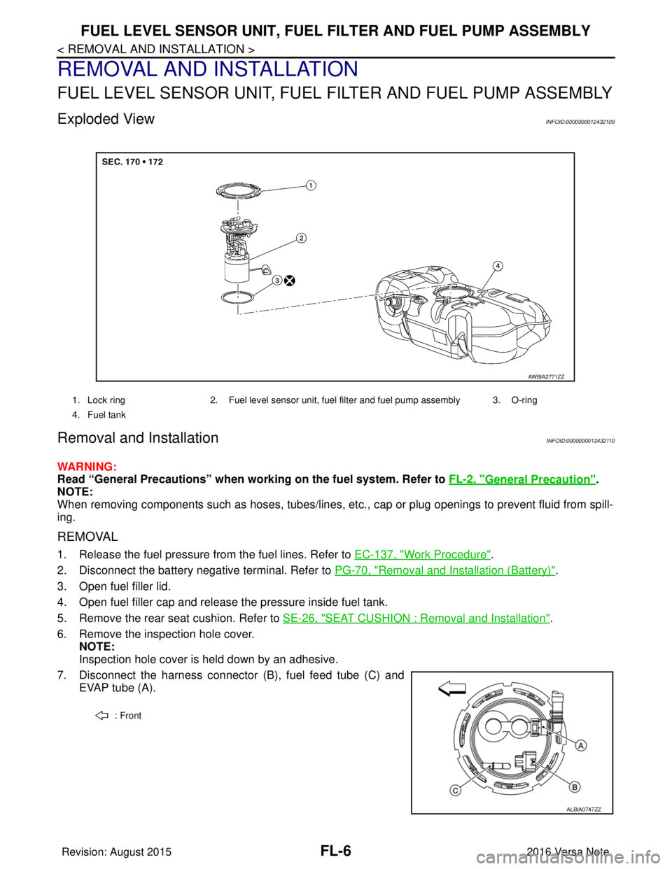
Exploded ViewINFOID:0000000012432109
Removal and InstallationINFOID:0000000012432110
WARNING:
Read “General Precautions” when wo rking on the fuel system. Refer to FL-2, "
General Precaution".
NOTE:
When removing components such as hoses, tubes/lines, etc. , cap or plug openings to prevent fluid from spill-
ing.
REMOVAL
1. Release the fuel pressure from the fuel lines. Refer to EC-137, "Work Procedure".
2. Disconnect the battery negative terminal. Refer to PG-70, "
Removal and Installation (Battery)".
3. Open fuel filler lid.
4. Open fuel filler cap and release the pressure inside fuel tank.
5. Remove the rear seat cushion. Refer to SE-26, "
SEAT CUSHION : Removal and Installation".
6. Remove the inspection hole cover. NOTE:
Inspection hole cover is held down by an adhesive.
7. Disconnect the harness connector (B), fuel feed tube (C) and EVAP tube (A).
1. Lock ring 2. Fuel level sensor unit, fuel filter and fuel pump assembly 3. O-ring
4. Fuel tank
AWBIA2771ZZ
: Front
ALBIA0747ZZ
Revision: August 2015 2016 Versa Note
cardiagn.com
Page 1876 of 3641

FL-10
< REMOVAL AND INSTALLATION >
FUEL TANK
FUEL TANK
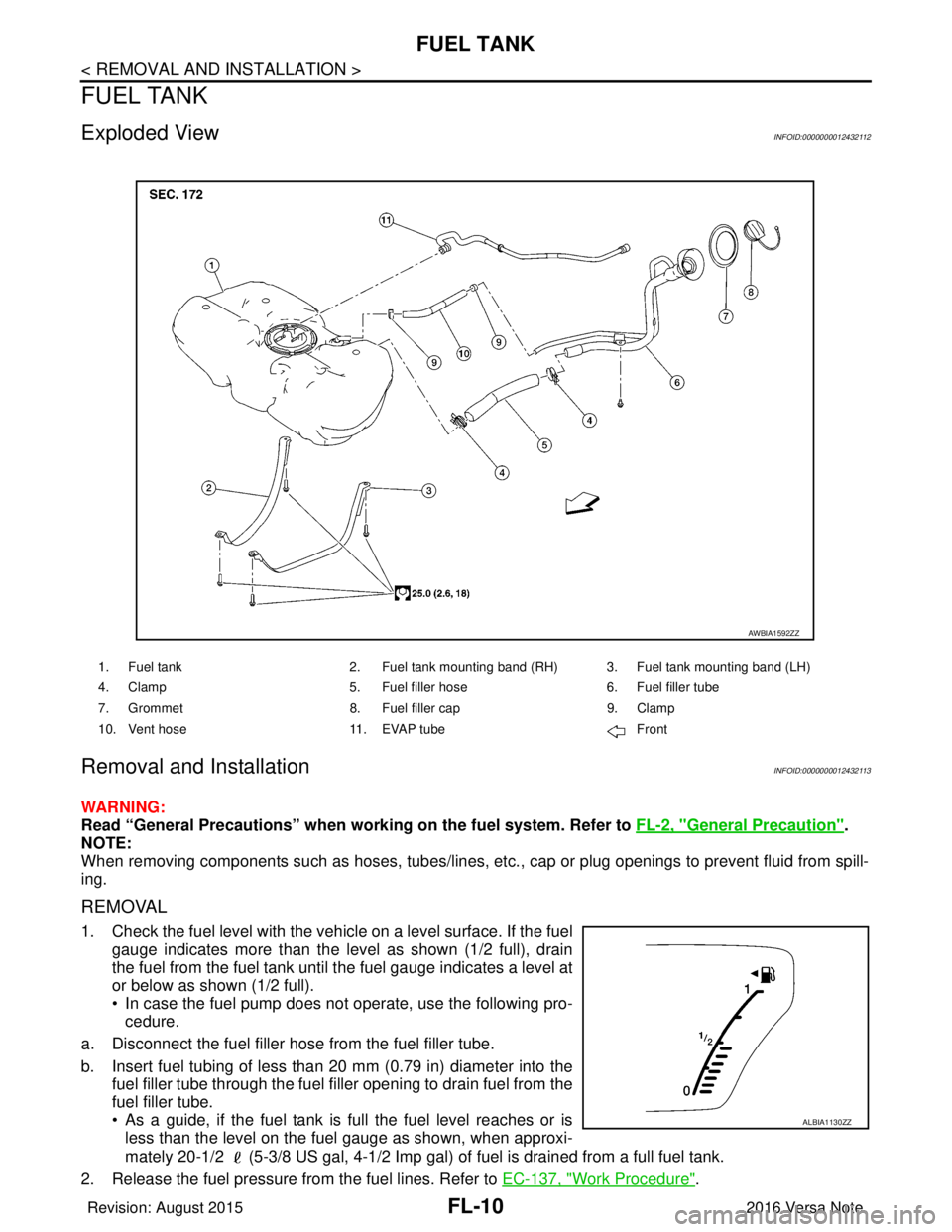
Exploded ViewINFOID:0000000012432112
Removal and InstallationINFOID:0000000012432113
WARNING:
Read “General Precautions” when working on the fuel system. Refer to FL-2, "
General Precaution".
NOTE:
When removing components such as hoses, tubes/lines, etc. , cap or plug openings to prevent fluid from spill-
ing.
REMOVAL
1. Check the fuel level with the vehicle on a level surface. If the fuel gauge indicates more than the level as shown (1/2 full), drain
the fuel from the fuel tank until the fuel gauge indicates a level at
or below as shown (1/2 full).
• In case the fuel pump does not operate, use the following pro-cedure.
a. Disconnect the fuel filler hose from the fuel filler tube.
b. Insert fuel tubing of less than 20 mm (0.79 in) diameter into the fuel filler tube through the fuel f iller opening to drain fuel from the
fuel filler tube.
• As a guide, if the fuel tank is full the fuel level reaches or is less than the level on the fuel gauge as shown, when approxi-
mately 20-1/2 (5-3/8 US gal, 4-1/2 Imp gal) of fuel is drained from a full fuel tank.
2. Release the fuel pressure from the fuel lines. Refer to EC-137, "
Work Procedure".
1. Fuel tank2. Fuel tank mounting band (RH) 3. Fuel tank mounting band (LH)
4. Clamp 5. Fuel filler hose 6. Fuel filler tube
7. Grommet 8. Fuel filler cap 9. Clamp
10. Vent hose 11. EVAP tube Front
AWBIA1592ZZ
ALBIA1130ZZ
Revision: August 2015 2016 Versa Note
cardiagn.com
Page 1877 of 3641

FUEL TANKFL-11
< REMOVAL AND INSTALLATION >
C
DE
F
G H
I
J
K L
M A
FL
NP
O
3. Open fuel filler lid.
4. Open fuel filler cap and release
the pressure inside fuel tank.
5. Remove the rear seat cushion. Refer to SE-26, "
SEAT CUSHION : Removal and Installation".
6. Remove the inspection hole cover. NOTE:
Inspection hole cover is held by an adhesive.
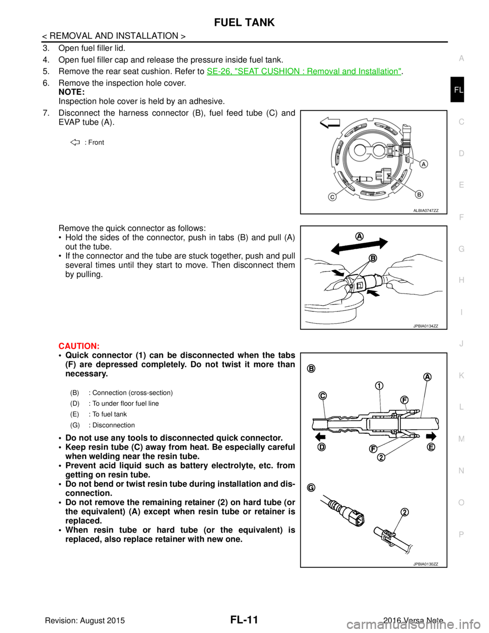
7. Disconnect the harness connector (B), fuel feed tube (C) and
EVAP tube (A).
Remove the quick connector as follows:
• Hold the sides of the connector, push in tabs (B) and pull (A) out the tube.
• If the connector and the tube are stuck together, push and pull several times until they start to move. Then disconnect them
by pulling.
CAUTION:
• Quick connector (1) can be disconnected when the tabs (F) are depressed completely. Do not twist it more than
necessary.
• Do not use any tools to disconnected quick connector.
• Keep resin tube (C) away from heat. Be especially careful when welding near the resin tube.
• Prevent acid liquid such as battery electrolyte, etc. from getting on resin tube.
• Do not bend or twist resin tube during installation and dis- connection.
• Do not remove the remaining retainer (2) on hard tube (or the equivalent) (A) except when resin tube or retainer is
replaced.
• When resin tube or hard tube (or the equivalent) is replaced, also replace retainer with new one.
: Front
ALBIA0747ZZ
JPBIA0134ZZ
(B) : Connection (cross-section)
(D) : To under floor fuel line
(E) : To fuel tank
(G) : Disconnection
JPBIA0130ZZ
Revision: August 2015 2016 Versa Note
cardiagn.com