2016 NISSAN NOTE air suspension
[x] Cancel search: air suspensionPage 1850 of 3641
NOISE, VIBRATION AND HARSHNESS (NVH) TROUBLESHOOTINGFSU-5
< SYMPTOM DIAGNOSIS >
C
DF
G H
I
J
K L
M A
B
FSU
N
O P
SYMPTOM DIAGNOSIS
NOISE, VIBRATION AND HARSHN ESS (NVH) TROUBLESHOOTING
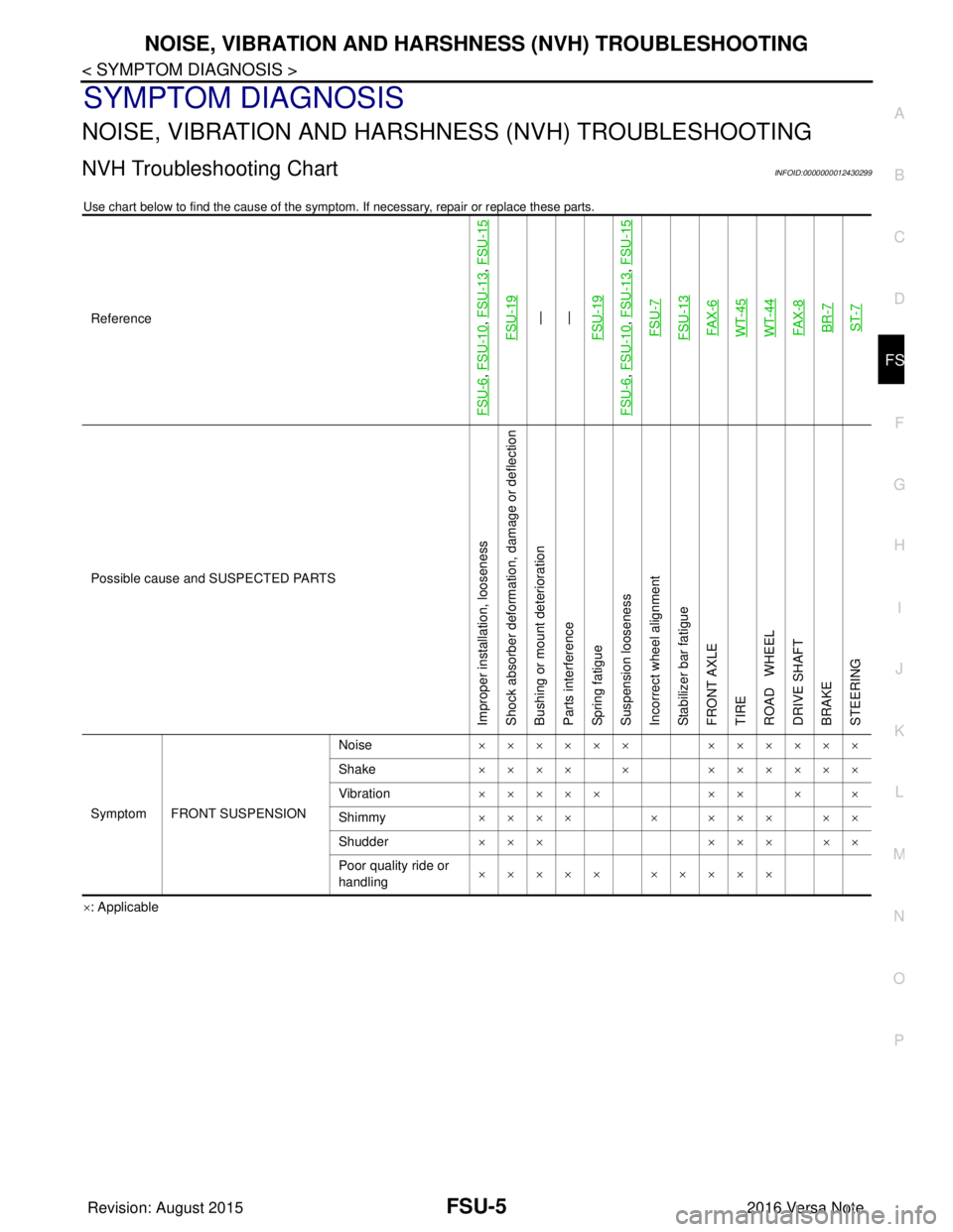
NVH Troubleshooting ChartINFOID:0000000012430299
Use chart below to find the cause of the symptom . If necessary, repair or replace these parts.
×: ApplicableReference
FSU-6
, FSU-10
, FSU-13
,
FSU-15
FSU-19
—
—
FSU-19
FSU-6
, FSU-10
, FSU-13
, FSU-15
FSU-7FSU-13FA X - 6WT-45WT-44FA X - 8BR-7ST-7
Possible cause and SUSPECTED PARTS
Improper installation, looseness
Shock absorber deformation, damage or deflection
Bushing or mount deterioration
Parts interference
Spring fatigue
Suspension looseness
Incorrect wheel alignment
Stabilizer bar fatigue
FRONT AXLE
TIRE
ROAD WHEEL
DRIVE SHAFT
BRAKE
STEERING
Symptom FRONT SUSPENSION Noise
×××××× ××××××
Shake ×××× × ××××××
Vibration ××××× ×× × ×
Shimmy ×××× × ××× ××
Shudder ××× ××× ××
Poor quality ride or
handling ××××× ×××××
Revision: August 2015
2016 Versa Note
cardiagn.com
Page 1852 of 3641
WHEEL ALIGNMENTFSU-7
< PERIODIC MAINTENANCE >
C
DF
G H
I
J
K L
M A
B
FSU
N
O P
WHEEL ALIGNMENT
InspectionINFOID:0000000012430301
PRELIMINARY INSPECTION
WARNING:
Always adjust the wheel alignment with the vehicle on a flat surface.
NOTE:
If the wheel alignment is out of s pecification, inspect and replace any damaged or worn rear suspension parts
before making any adjustments.
1. Check and adjust the wheel alignment with the vehicle under unladen conditions. “Unladen conditions”
means that the fuel, engine coolant, and lubricants are full; the spare tire, jack, hand tools and mats are in
designated positions.
2. Check the tires for incorrect air pressure and excessive wear.
3. Check the wheels for run out and damage. Refer to WT-54, "
Wheel".
4. Check the wheel bearing axial end play. Refer to FAX-27, "
Wheel Bearing".
5. Check the shock absorbers for leaks or damage.
6. Check each mount point of the suspension co mponents for any excessive looseness or damage.
7. Check each link, arm, and the suspension member for any damage.
8. Check the vehicle height. Refer to FSU-21, "
Wheelarch Height (Unladen*)".
GENERAL INFORMATION AND RECOMMENDATIONS
1. A Four-Wheel Thrust Alignment should be performed.
• This type of alignment is recomm ended for any NISSAN/INFINITI vehicle.
• The four-wheel “thrust” process helps ensure that the vehicle is properly aligned and the steering wheel
is centered.
• The alignment machine itself should be capabl e of accepting any NISSAN/INFINITI vehicle.
• The alignment machine should be checked to ensure that it is level.
2. Make sure the alignment machine is properly calibrated. • Your alignment machine should be regularly calibrated in order to give correct information.
• Check with the manufacturer of your specific a lignment machine for their recommended Service/Cali-
bration Schedule.
ALIGNMENT PROCESS
IMPORTANT: Use only the alignment specifications listed in this Service Manual. Refer to FSU-20, "Wheel
Alignment (Unladen*1)".
• When displaying the alignment settings, many alignment machines use “indicators”: (Green/red, plus or
minus, Go/No Go). Do NOT use these indicators.
- The alignment specifications programmed into your alignment machine that operate these indicators may
not be correct.
- This may result in an ERROR.
• Most camera-type alignment machines are equipped with "Rolling Compensation" method and optional
"Jacking Compensation" method to "compensate" the alignment targets or head units.
"Rolling Compensation" is the preferred method.
- If using the "Rolling Compensation" method, after inst alling the alignment targets or head units, push or pull
on the rear wheel to move the vehicle. Do not push or pull on the vehicle body.
- If using the "Jacking Compensation" method, after inst alling the alignment targets or head units, raise the
vehicle and rotate the wheels 1/2 turn in either direction.
NOTE:
Do not use the "Rolling Compensation" method if you are using sensor-type alignment equipment.
• Follow all instructions for the alignment machine you're using for more information.
CAMBER, CASTER AND KINGPIN INCLINATION ANGLES INSPECTION
• Camber, caster, kingpin inclination angles cannot be adjusted.
• Before inspection, set the front wheels onto a turning radius gauge. Set the rear wheels onto a pad that has
the same height so the vehicle will remain horizontal.
TOTAL TOE-IN INSPECTION
Measure the total toe-in using the following procedure.
Revision: August 2015 2016 Versa Note
cardiagn.com
Page 2722 of 3641

RAX-4
< SYMPTOM DIAGNOSIS >
NOISE, VIBRATION AND HARSHNESS (NVH) TROUBLESHOOTING
SYMPTOM DIAGNOSIS
NOISE, VIBRATION AND HARSHNESS (NVH) TROUBLESHOOTING
NVH Troubleshooting ChartINFOID:0000000012431908
Use chart below to find the cause of the symptom. If necessary, repair or replace these parts.
×: ApplicableReference page
RSU-5—
RAX-5RSU-4WT-43WT-45BR-7
Possible cause and SUSPECTED PARTS
Improper installation, looseness
Parts interference
Wheel bearing damage
REAR SUSPENSION
TIRE
ROAD WHEEL
BRAKE
Symptom Noise
×××××××
Shake ×××××××
Vibration ×××××
Shimmy ×× ××××
Shudder ×××× ×
Poor quality ride or handling ×× ×××
Revision: August 2015 2016 Versa Note
cardiagn.com
Page 2729 of 3641

RSU-1
SUSPENSION
C
DF
G H
I
J
K L
M
SECTION RSU
A
B
RSU
N
O PCONTENTS
REAR SUSPENSION
PRECAUTION ....... ........................................2
PRECAUTIONS .............................................. .....2
Precaution for Supplemental Restraint System
(SRS) "AIR BAG" and "SEAT BELT PRE-TEN-
SIONER" ............................................................. ......
2
Precaution for Suspension ........................................2
PREPARATION ............................................3
PREPARATION .............................................. .....3
Special Service Tool ........................................... ......3
Commercial Service Tools ........................................3
SYMPTOM DIAGNOSIS ...............................4
NOISE, VIBRATION AND HARSHNESS
(NVH) TROUBLESHOOTING ........................ .....
4
NVH Troubleshooting Chart ................................ ......4
PERIODIC MAINTENANCE ..........................5
REAR SUSPENSION ASSEMBLY ................ .....5
Inspection ............................................................ ......5
WHEEL ALIGNMENT ..........................................6
Inspection ............................................................ ......6
REMOVAL AND INSTALLATION ................8
REAR SHOCK ABSORBER ..............................8
Exploded View ..................................................... .....8
Removal and Installation ..........................................8
Inspection .................................................................9
Disposal ...................................................................10
COIL SPRING ...................................................11
Exploded View .........................................................11
Removal and Installation .........................................11
Inspection ................................................................12
REAR SUSPENSION BEAM ............................13
Exploded View ..................................................... ....13
Removal and Installation .........................................13
Inspection ................................................................14
SERVICE DATA AND SPECIFICATIONS
(SDS) ............... .......................................... ...
15
SERVICE DATA AND SPECIFICATIONS
(SDS) .................................................................
15
Wheel Alignment (Unladen*1) ..................................15
Wheelarch Height (Unladen*) .............................. ....15
Revision: August 2015 2016 Versa Note
cardiagn.com
Page 2730 of 3641

RSU-2
< PRECAUTION >
PRECAUTIONS
PRECAUTION
PRECAUTIONS
Precaution for Supplemental Restraint System (SRS) "AIR BAG" and "SEAT BELT
PRE-TENSIONER"
INFOID:0000000012431916
The Supplemental Restraint System such as “A IR BAG” and “SEAT BELT PRE-TENSIONER”, used along
with a front seat belt, helps to reduce the risk or severity of injury to the driver and front passenger for certain
types of collision. Information necessary to service the system safely is included in the SR and SB section of
this Service Manual.
WARNING:
• To avoid rendering the SRS inopera tive, which could increase the risk of personal injury or death in
the event of a collision which would result in air bag inflation, all maintenance must be performed by
an authorized NISSAN/INFINITI dealer.
• Improper maintenance, including in correct removal and installation of the SRS, can lead to personal
injury caused by unintent ional activation of the system. For re moval of Spiral Cable and Air Bag
Module, see the SR section.
• Do not use electrical test equipmen t on any circuit related to the SRS unless instructed to in this
Service Manual. SRS wiring harn esses can be identified by yellow and/or orange harnesses or har-
ness connectors.
PRECAUTIONS WHEN USING POWER TOOLS (AIR OR ELECTRIC) AND HAMMERS
WARNING:
• When working near the Airbag Diagnosis Sensor Unit or other Airbag System sensors with the Igni-
tion ON or engine running, DO NOT use air or electri c power tools or strike near the sensor(s) with a
hammer. Heavy vibration could activate the sensor( s) and deploy the air bag(s), possibly causing
serious injury.
• When using air or electric power tools or hammers , always switch the Ignition OFF, disconnect the
battery and wait at least three minutes before performing any service.
Precaution for SuspensionINFOID:0000000012431917
• When installing rubber bushings, the final tightening mu st be carried out under unladen conditions with tires
on ground. Spilled oil might shorten the life of rubber bushings. Be sure to wipe off any spilled oil.
- Unladen conditions mean that fuel, engine coolant and lubricant are full. Spare tire, jack, hand tools and mats are in designated positions.
• After servicing suspension parts, be sure to check wheel alignment.
• Self-lock nuts are not reusable. Always use new ones when installing. Since new self-lock nuts are pre-oiled,
tighten as they are.
• The tightening surface must be kept free of oil/grease.
• When jacking up the vehicle with a floor jack, do not hang the jack on the suspension beam.
Revision: August 2015 2016 Versa Note
cardiagn.com
Page 2732 of 3641

RSU-4
< SYMPTOM DIAGNOSIS >
NOISE, VIBRATION AND HARSHNESS (NVH) TROUBLESHOOTING
SYMPTOM DIAGNOSIS
NOISE, VIBRATION AND HARSHNESS (NVH) TROUBLESHOOTING
NVH Troubleshooting ChartINFOID:0000000012431920
Use chart below to find the cause of the symptom. If necessary, repair or replace these parts.
×: ApplicableReference
RSU-8
,
RSU-11
, RSU-13
RSU-8—
—
RSU-12
RSU-8
, RSU-11
, RSU-13
RSU-6RAX-4WT-45WT-44BR-7
Possible cause and SUSPECTED PARTS
Improper installation, looseness
Shock absorber deformation, damage or deflection
Bushing or mounting deterioration
Parts interference
Spring fatigue
Suspension looseness
Incorrect wheel alignment
REAR AXLE
TIRE
ROAD WHEEL
BRAKE
Symptom REAR SUSPENSION Noise
×××××× ××××
Shake ×××× × ××××
Vibration ××××× ××
Shimmy ×××× ×××××
Shudder ××× ××××
Poor quality ride or handling ××××× ××××
Revision: August 2015 2016 Versa Note
cardiagn.com
Page 2734 of 3641

RSU-6
< PERIODIC MAINTENANCE >
WHEEL ALIGNMENT
WHEEL ALIGNMENT
InspectionINFOID:0000000012431922
DESCRIPTION
Measure the wheel alignment under unladen conditions.
NOTE:
“Unladen conditions” means that fuel, engine coolant, and lubricants are full. Spare tire, jack, hand tools and
mats are in designated positions.
PRELIMINARY
Check the following:
1. Tires for improper air pressure and wear.
2. Road wheels for runout. Refer to WT-44, "
Inspection".
3. Wheel bearing axial end play. Refer to RAX-10, "
Wheel Bearing".
4. Shock absorber operation.
5. Each mounting part of suspension for looseness and deformation.
6. Rear suspension beam for cracks, deformation, and other damage.
7. Vehicle height (posture).
GENERAL INFORMATION AND RECOMMENDATIONS
1. A Four-Wheel Thrust Alignment should be performed. • This type of alignment is recommended for any NISSAN/INFINITI vehicle.
• The four-wheel “thrust” process helps ensure that the vehicle is properly aligned and the steering wheel
is centered.
• The alignment machine itself should be capabl e of accepting any NISSAN/INFINITI vehicle.
• The alignment machine should be checked to ensure that it is level.
2. Make sure the alignment machine is properly calibrated. • Your alignment machine should be regularly calibrated in order to give correct information.
• Check with the manufacturer of your specific al ignment machine for their recommended Service/Cali-
bration Schedule.
THE ALIGNMENT PROCESS
IMPORTANT: Use only the alignment specifications listed in this Service Manual. Refer to RSU-15, "Wheel
Alignment (Unladen*1)".
1. When displaying the alignment settings, many alignment machines use “indicators”: (Green/red, plus or minus, Go/No Go). Do NOT use these indicators.
• The alignment specifications programmed into your alignment machine that operate these indicators may not be correct.
• This may result in an ERROR.
2. Most camera-type alignment machines are equipped with both "Rolling Compensation" method and optional "Jacking Compensation" method to "com pensate" the alignment targets or head units.
"Rolling Compensation" is the preferred method.
• If using the "Rolling Compensation" method, after installing the alignment targets or head units, push or pull on the rear wheel to move the vehicle. Do not push or pull the vehicle body.
• If using the "Jacking Compensation" method, after in stalling the alignment targets or head units, raise
the vehicle and rotate the wheels 1/2 turn both ways.
NOTE:
Do not use the "rolling compensation" if you are using sensor-type alignment equipment.
• Follow all instructions for the alignment machine you're using for more information.
CAMBER INSPECTION
• Measure camber of both right and left wheels with a suitable alignment gauge.
• If it is out of the specificati on value, inspect and replace any damaged or worn rear suspension parts.
Camber : Refer to RSU-15, "
Wheel Alignment
(Unladen*1)".
Revision: August 2015
2016 Versa Note
cardiagn.com
Page 2744 of 3641

WT-1
SUSPENSION
C
DF
G H
I
J
K L
M
SECTION WT
A
B
WT
N
O PCONTENTS
ROAD WHEELS & TIRES
PRECAUTION ....... ........................................3
PRECAUTIONS .............................................. .....3
Precaution for Supplemental Restraint System
(SRS) "AIR BAG" and "SEAT BELT PRE-TEN-
SIONER" ............................................................. ......
3
Service Notice and Precautions for TPMS ................3
Service Notice and Precautions for Road Wheel ......3
PREPARATION ............................................5
PREPARATION .............................................. .....5
Special Service Tool ........................................... ......5
Commercial Service Tool ..........................................5
SYSTEM DESCRIPTION ..............................6
COMPONENT PARTS ................................... .....6
Component Parts Location .................................. ......6
Component Description .............................................6
BCM ..........................................................................6
Remote Keyless Entry Receiver ...............................6
Transmitter ................................................................7
Low Tire Pressure Warning Lamp .............................7
SYSTEM ......................................................... .....8
TIRE PRESSURE MONITORING SYSTEM .......... ......8
TIRE PRESSURE MONITORING SYSTEM : Sys-
tem Diagram ..............................................................
8
TIRE PRESSURE MONITORING SYSTEM : Sys-
tem Description .........................................................
8
TIRE PRESSURE MONITORING SYSTEM :
Easy Fill Tire Alert Function ......................................
8
DIAGNOSIS SYSTEM (BCM) ............................10
WITH INTELLIGENT KEY ..................................... ....10
WITH INTELLIGENT KEY : CONSULT Function
(BCM - COMMON ITEM) ........................................
10
WITH INTELLIGENT KEY : CONSULT Function
(BCM - AIR PRESSURE MONITOR) ......................
11
WITHOUT INTELLIGENT KEY .............................. ....11
WITHOUT INTELLIGENT KEY : CONSULT Func-
tion (BCM - COMMON ITEM) ..................................
11
WITHOUT INTELLIGENT KEY : CONSULT Func-
tion (BCM - AIR PRESSURE MONITOR) ...............
12
ECU DIAGNOSIS INFORMATION ..............14
BCM ...................................................................14
List of ECU Reference ......................................... ....14
WIRING DIAGRAM ......................................15
TIRE PRESSURE MONITORING SYSTEM ......15
Wiring Diagram - With Inte lligent Key ......................15
Wiring Diagram - Without Intelligent Ke y .................18
BASIC INSPECTION ....... ............................21
DIAGNOSIS AND REPAIR WORK FLOW .......21
Work Flow ............................................................ ....21
ID REGISTRATION PROCEDURE ...................22
Description ...............................................................22
Work Procedure .......................................................22
DTC/CIRCUIT DIAGNOSIS .........................25
C1704, C1705, C1706, C1707 LOW TIRE
PRESSURE .......................................................
25
DTC Logic ............................................................ ....25
Diagnosis Procedure ...............................................25
C1708, C1709, C1710, C1711 TRANSMITTER
(NO DATA) ........................................................
27
DTC Logic ............................................................ ....27
Diagnosis Procedure ...............................................27
C1716, C1717, C1718, C1719 TRANSMITTER
(PRESSURE DATA) ..........................................
30
DTC Logic ............................................................ ....30
Diagnosis Procedure ...............................................30
Revision: August 2015 2016 Versa Note
cardiagn.com