2016 MERCEDES-BENZ GLS SUV rear view mirror
[x] Cancel search: rear view mirrorPage 218 of 397
The distance specifications apply only to
objects that are at ground level.
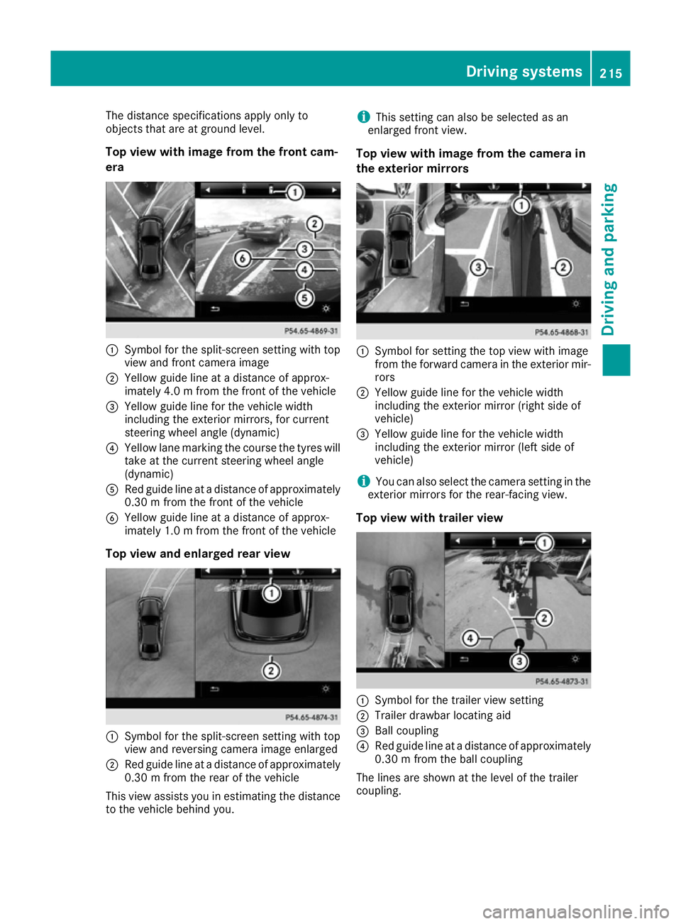
Top view with image from the front cam-
era :
Symbol for the split-screen setting with top
view and front camera image
; Yellow guide line at a distance of approx-
imately 4.0 m from the front of the vehicle
= Yellow guide line for the vehicle width
including the exterior mirrors, for current
steering wheel angle (dynamic)
? Yellow lane marking the course the tyres will
take at the current steering wheel angle
(dynamic)
A Red guide line at a distance of approximately
0.30 mfrom the front of the vehicle
B Yellow guide line at a distance of approx-
imately 1.0 m from the front of the vehicle
Top view and enlarged rear view :
Symbol for the split-screen setting with top
view and reversing camera image enlarged
; Red guide line at a distance of approximately
0.30 m from the rear of the vehicle
This view assists you in estimating the distance to the vehicle behind you. i
This setting can also be selected as an
enlarged front view.
Top view with image from the camera in
the exterior mirrors :
Symbol for setting the top view with image
from the forward camera in the exterior mir-
rors
; Yellow guide line for the vehicle width
including the exterior mirror (right side of
vehicle)
= Yellow guide line for the vehicle width
including the exterior mirror (left side of
vehicle)
i You can also select the camera setting in the
exterior mirrors for the rear-facing view.
Top view with trailer view :
Symbol for the trailer view setting
; Trailer drawbar locating aid
= Ball coupling
? Red guide line at a distance of approximately
0.30 m from the ball coupling
The lines are shown at the level of the trailer
coupling. Driving systems
215Driving and parking Z
Page 325 of 397
Sun visors
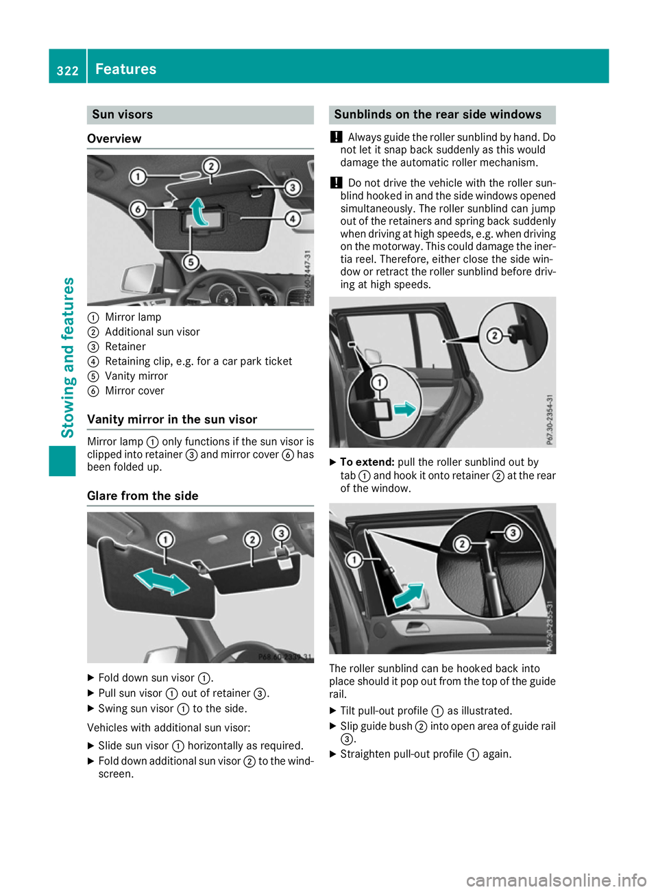
Overview :
Mirror lamp
; Additional sun visor
= Retainer
? Retaining clip, e.g. for a car park ticket
A Vanity mirror
B Mirror cover
Vanity mirror in the sun visor Mirror lamp
:only functions if the sun visor is
clipped into retainer =and mirror cover Bhas
been folded up.
Glare from the side X
Fold down sun visor :.
X Pull sun visor :out of retainer =.
X Swing sun visor :to the side.
Vehicles with additional sun visor:
X Slide sun visor :horizontally as required.
X Fold down additional sun visor ;to the wind-
screen. Sunblinds on the rear side windows
! Always guide the roller sunblind by hand. Do
not let it snap back suddenly as this would
damage the automatic roller mechanism.
! Do not drive the vehicle with the roller sun-
blind hooked in and the side windows opened simultaneously. The roller sunblind can jump
out of the retainers and spring back suddenly
when driving at high speeds, e.g. when driving on the motorway. This could damage the iner-
tia reel. Therefore, either close the side win-
dow or retract the roller sunblind before driv- ing at high speeds. X
To extend: pull the roller sunblind out by
tab :and hook it onto retainer ;at the rear
of the window. The roller sunblind can be hooked back into
place should it pop out from the top of the guide
rail.
X Tilt pull-out profile :as illustrated.
X Slip guide bush ;into open area of guide rail
=.
X Straighten pull-out profile :again. 322
FeaturesStowing and features
Page 329 of 397
cle. You can then no longer make calls using the
hands-free system.
If a call is active and you remove the key from
the ignition lock, the conversation is transferred over to the mobile phone. It is then possible to
continue the conversation on the mobile phone. Garage door opener
General notes The HomeLink
®
garage door opener integrated
in the rear-view mirror allows you to operate up
to three different door and gate systems.
Once programmed, the integrated garage door
opener in the rear-view mirror will assume the
function of the garage door system's remote
control. Please also read the operating instruc-
tions for the garage door system.
When programming a garage door opener, park
the vehicle outside the garage. Do not run the
engine while programming.
The garage door opener is only available for cer- tain countries. Observe the legal requirements
for each individual country.
The HomeLink ®
garage door opener is compat-
ible with most European garage and gate opener
drives. More information on HomeLink ®
and/or
compatible products is available:
R at a qualified specialist workshop
R via the HomeLink ®
Hotline
(0) 08000 466 354 65 or alternatively
+49 (0) 6838 907-277
R on the Internet at http://www.homelink.com
Important safety notes G
WARNING
When you operate or program the garage door with the integrated garage door opener, per-
sons in the range of movement of the garage
door can become trapped or struck by the
garage door. There is a risk of injury.
When using the integrated garage door
opener, always make sure that nobody is
within the range of movement of the garage
door. G
WARNING
Combustion engines emit poisonous exhaust
gases such as carbon monoxide. Inhaling
these exhaust gases leads to poisoning. There is a risk of fatal injury. Therefore never leave
the engine running in enclosed spaces with-
out sufficient ventilation.
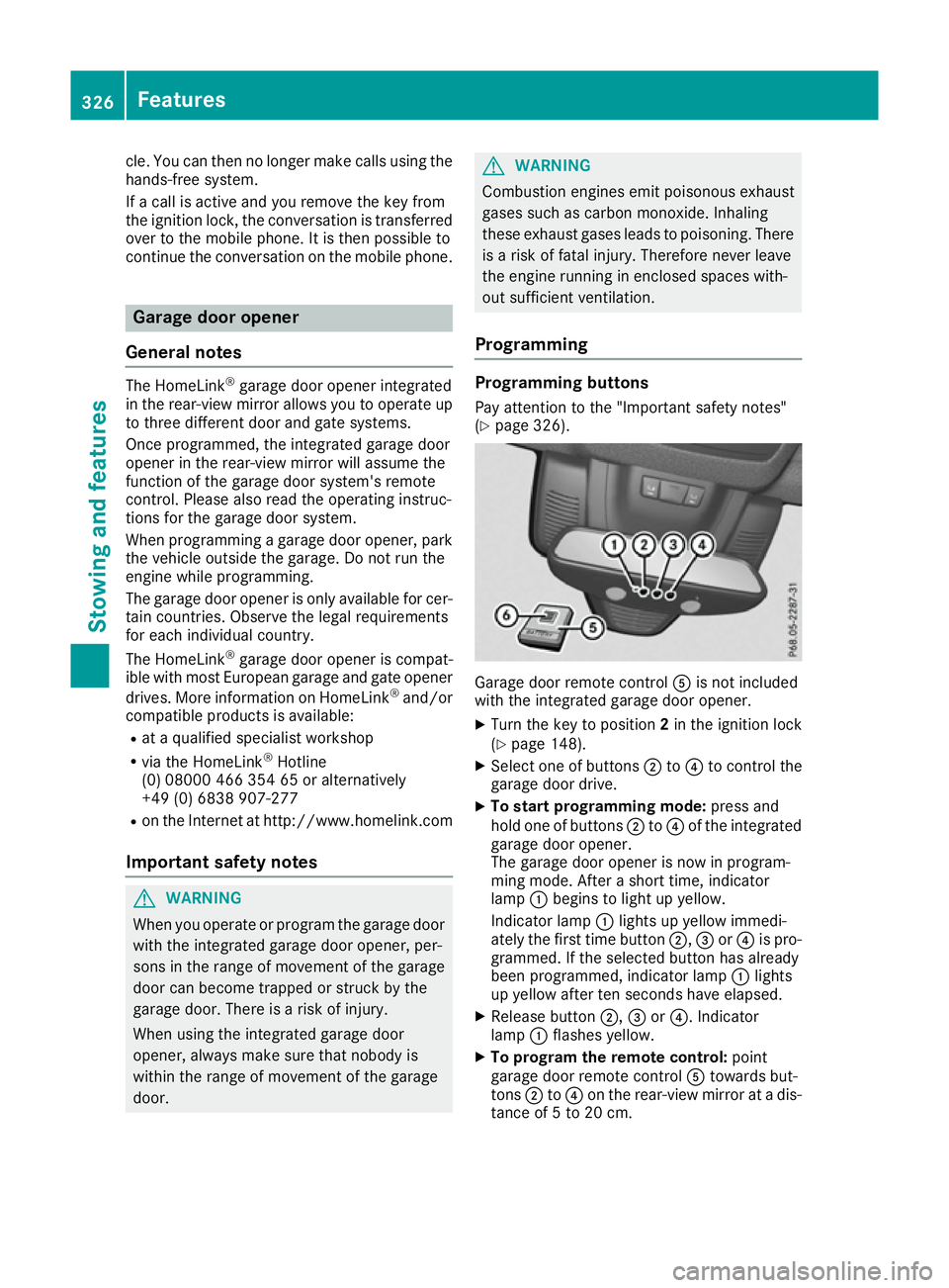
Programming Programming buttons
Pay attention to the "Important safety notes"
(Y page 326). Garage door remote control
Ais not included
with the integrated garage door opener.
X Turn the key to position 2in the ignition lock
(Y page 148).
X Select one of buttons ;to? to control the
garage door drive.
X To start programming mode: press and
hold one of buttons ;to? of the integrated
garage door opener.
The garage door opener is now in program-
ming mode. After a short time, indicator
lamp :begins to light up yellow.
Indicator lamp :lights up yellow immedi-
ately the first time button ;,=or? is pro-
grammed. If the selected button has already
been programmed, indicator lamp :lights
up yellow after ten seconds have elapsed.
X Release button ;,=or?. Indicator
lamp :flashes yellow.
X To program the remote control: point
garage door remote control Atowards but-
tons ;to? on the rear-view mirror at a dis-
tance of 5 to 20 cm. 326
FeaturesStowing and features
Page 330 of 397
X
Press and hold button Bon remote control
A until indicator lamp :lights up green.
When indicator lamp :lights up green: pro-
gramming is finished.
When indicator lamp :flashes green: pro-
gramming was successful. The next step is to synchronise the rolling code (Y page 327).
X Release button Bof remote control Aof the
garage door drive.
If indicator lamp :lights up red: repeat the
programming process for the corresponding
button on the rear-view mirror. When doing
so, vary the distance between remote control A and the rear-view mirror.
The required distance between remote con-
trol Aand the integrated garage door opener
depends on the garage door drive system.
Several attempts may be required. You
should test every position for at least
25 seconds before trying another position.
Synchronising the rolling code
Observe the "Important safety notes"
(Y page 326).
If the garage door system uses a rolling code,
you will also have to synchronise the garage
door system with the integrated garage door
opener in the rear-view mirror. To do this, you
will need to use the programming button on the door drive control panel. The programming but-
ton may be placed at different locations depend- ing on the manufacturer. It is usually located on
the door drive unit on the garage ceiling.
Familiarise yourself with the garage door drive
operating instructions, e.g. under "Program-
ming of additional remote controls", before car-
rying out the following steps.
Your vehicle must be within range of the garage
door or gate opener drive. Make sure that nei-
ther your vehicle nor any persons/objects are
present within the sweep of the door or gate.
X Turn the key to position 2in the ignition lock
(Y page 148).
X Get out of the vehicle.
X Press the programming button on the door
drive unit.
Usually, you now have 30 seconds to initiate
the next step. X
Get into the vehicle.
X Press previously programmed button ;,=
or ? of the integrated garage door opener
until the door closes.
The rolling code synchronisation is then com- plete.
Problems when programming
If you have problems when programming the
integrated garage door opener, please note the following:
R Check the transmitter frequency used by
garage door drive remote control Aand
whether it is supported. The transmitter fre-
quency can usually be found on the back of
remote control Afor the garage door drive.
R Replace the batteries in garage door remote
control A. This increases the likelihood that
garage door remote control Awill transmit a
strong and precise signal to the integrated
garage door opener in the rear-view mirror.
R When programming, hold remote control A
at varying distances and angles from but-
tons ;to? which you are programming. Try
various angles at a distance between 5and
20 cm or at the same angle but at varying
distances.
R If another remote control Ais available for
the same garage door drive, perform the pro-
gramming steps again using this remote con- trol A. Before performing these steps, make
sure that new batteries have been fitted in
garage door drive remote control A.
R Note that some remote controls transmit only
for a limited period (the indicator lamp on theremote control goes out). Press button Bon
remote control Aagain before transmission
ends.
R Align the aerial cable of the garage door
opener unit. This can improve signal recep-
tion/transmission.
Opening or closing the garage door Once programmed, the integrated garage door
opener will assume the function of the garage
door system's remote control. Please also read
the operating instructions for the garage door
system. Features
327Stowing and features Z
Page 331 of 397
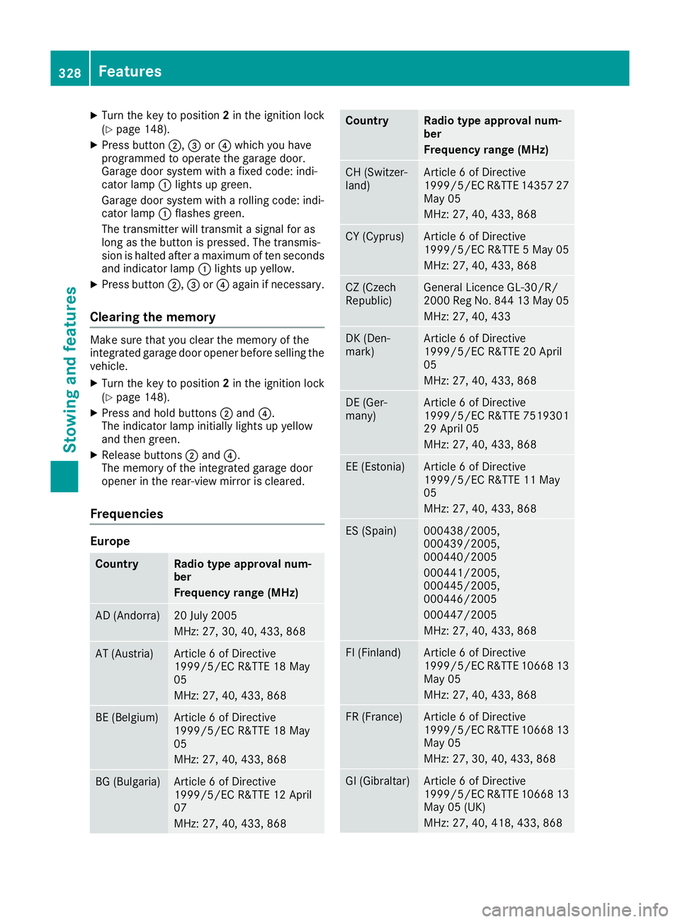
X
Turn the key to position 2in the ignition lock
(Y page 148).
X Press button ;,=or? which you have
programmed to operate the garage door.
Garage door system with a fixed code: indi-
cator lamp :lights up green.
Garage door system with a rolling code: indi-
cator lamp :flashes green.
The transmitter will transmit a signal for as
long as the button is pressed. The transmis-
sion is halted after a maximum of ten seconds
and indicator lamp :lights up yellow.
X Press button ;,=or? again if necessary.
Clearing the memory Make sure that you clear the memory of the
integrated garage door opener before selling the vehicle.
X Turn the key to position 2in the ignition lock
(Y page 148).
X Press and hold buttons ;and ?.
The indicator lamp initially lights up yellow
and then green.
X Release buttons ;and ?.
The memory of the integrated garage door
opener in the rear-view mirror is cleared.
Frequencies Europe
Country Radio type approval num-
ber
Frequency range (MHz)
AD (Andorra) 20 July 2005
MHz: 27, 30, 40, 433, 868
AT (Austria) Article 6 of Directive
1999/5/EC R&TTE 18 May
05
MHz: 27, 40, 433, 868
BE (Belgium) Article 6 of Directive
1999/5/EC R&TTE 18 May
05
MHz: 27, 40, 433, 868
BG (Bulgaria) Article 6 of Directive
1999/5/EC R&TTE 12 April
07
MHz: 27, 40, 433, 868 Country Radio type approval num-
ber
Frequency range (MHz)
CH (Switzer-
land) Article 6 of Directive
1999/5/EC R&TTE 14357 27
May 05
MHz: 27, 40, 433, 868 CY (Cyprus) Article 6 of Directive
1999/5/EC R&TTE 5 May 05
MHz: 27, 40, 433, 868 CZ (Czech
Republic) General Licence GL-30/R/
2000 Reg No. 844 13 May 05
MHz: 27, 40, 433 DK (Den-
mark) Article 6 of Directive
1999/5/EC R&TTE 20 April
05
MHz: 27, 40, 433, 868
DE (Ger-
many) Article 6 of Directive
1999/5/EC R&TTE 7519301
29 April 05
MHz: 27, 40, 433, 868
EE (Estonia) Article 6 of Directive
1999/5/EC R&TTE 11 May
05
MHz: 27, 40, 433, 868
ES (Spain) 000438/2005,
000439/2005,
000440/2005
000441/2005,
000445/2005,
000446/2005
000447/2005
MHz: 27, 40, 433, 868
FI (Finland) Article 6 of Directive
1999/5/EC R&TTE 10668 13
May 05
MHz: 27, 40, 433, 868 FR (France) Article 6 of Directive
1999/5/EC R&TTE 10668 13
May 05
MHz: 27, 30, 40, 433, 868 GI (Gibraltar) Article 6 of Directive
1999/5/EC R&TTE 10668 13
May 05 (UK)
MHz: 27, 40, 418, 433, 868 328
FeaturesStowing and features