2016 MERCEDES-BENZ GLS SUV rear view mirror
[x] Cancel search: rear view mirrorPage 109 of 397
Removing and fitting the rear seat head
restraints
X To remove: pull the head restraint up to the
stop.
X Press release catch :and pull the head
restraint out of the guides.
X To refit: insert the head restraint so that the
notches on the bar are on the left-hand side
when viewed in the direction of travel.
X Push the head restraint down until you hear it
engage in position.
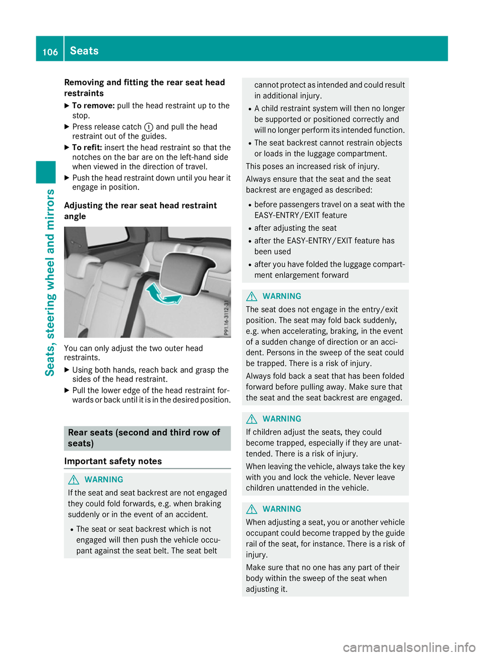
Adjusting the rear seat head restraint
angle You can only adjust the two outer head
restraints.
X Using both hands, reach back and grasp the
sides of the head restraint.
X Pull the lower edge of the head restraint for-
wards or back until it is in the desired position. Rear seats (second and third row of
seats)
Important safety notes G
WARNING
If the seat and seat backrest are not engaged they could fold forwards, e.g. when braking
suddenly or in the event of an accident.
R The seat or seat backrest which is not
engaged will then push the vehicle occu-
pant against the seat belt. The seat belt cannot protect as intended and could result
in additional injury.
R A child restraint system will then no longer
be supported or positioned correctly and
will no longer perform its intended function.
R The seat backrest cannot restrain objects
or loads in the luggage compartment.
This poses an increased risk of injury.
Always ensure that the seat and the seat
backrest are engaged as described:
R before passengers travel on a seat with the
EASY-ENTRY/EXIT feature
R after adjusting the seat
R after the EASY-ENTRY/EXIT feature has
been used
R after you have folded the luggage compart-
ment enlargement forward G
WARNING
The seat does not engage in the entry/exit
position. The seat may fold back suddenly,
e.g. when accelerating, braking, in the event
of a sudden change of direction or an acci-
dent. Persons in the sweep of the seat could
be trapped. There is a risk of injury.
Always fold back a seat that has been folded
forward before pulling away. Make sure that
the seat and the seat backrest are engaged. G
WARNING
If children adjust the seats, they could
become trapped, especially if they are unat-
tended. There is a risk of injury.
When leaving the vehicle, always take the key with you and lock the vehicle. Never leave
children unattended in the vehicle. G
WARNING
When adjusting a seat, you or another vehicle occupant could become trapped by the guiderail of the seat, for instance. There is a risk of
injury.
Make sure that no one has any part of their
body within the sweep of the seat when
adjusting it. 106
SeatsSeats, steering wheel and mirrors
Page 110 of 397
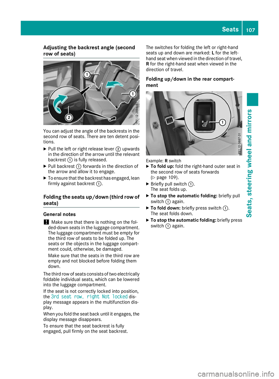
Adjusting the backrest angle (second
row of seats)
You can adjust the angle of the backrests in the
second row of seats. There are ten detent posi-
tions.
X Pull the left or right release lever ;upwards
in the direction of the arrow until the relevant
backrest :is fully released.
X Pull backrest :forwards in the direction of
the arrow and allow it to engage.
X To ensure that the backrest has engaged, lean
firmly against backrest :.
Folding the seats up/down (third row of seats) General notes
! Make sure that there is nothing on the fol-
ded-down seats in the luggage compartment.
The luggage compartment must be empty for
the third row of seats to be folded up. The
seats or the objects in the luggage compart-
ment could, otherwise, be damaged.
Make sure that the seats in the third row are
empty and not blocked before folding them
down.
The third row of seats consists of two electrically
foldable individual seats, which can be lowered
into the luggage compartment.
If the seat is not correctly locked into position,
the 3rd seat row, right Not locked 3rd seat row, right Not locked dis-
play message appears in the multifunction dis-
play.
When you fold the seat back until it engages, the display message disappears.
To ensure that the seat backrest is fully
engaged, pull firmly on the seat backrest. The switches for folding the left or right-hand
seats up and down are marked:
Lfor the left-
hand seat when viewed in the direction of travel,
R for the right-hand seat when viewed in the
direction of travel.
Folding up/down in the rear compart-
ment Example:
Rswitch
X To fold up: fold the right-hand outer seat in
the second row of seats forwards
(Y page 109).
X Briefly pull switch :.
The seat folds up.
X To stop the automatic folding: briefly pull
switch :again.
X To fold down: briefly press switch :.
The seat folds down.
X To stop the automatic folding: briefly press
switch :again. Seats
107Seats, steering wheel and mirrors Z
Page 119 of 397
Crash-responsive EASY-EXIT feature
If the crash-responsive EASY-EXIT feature is trig-
gered in an accident, the steering column will
move upwards when the driver's door is opened.
This occurs irrespective of the position of the
key in the ignition lock. This makes it easier to
exit the vehicle and rescue the occupants.
The crash-responsive EASY-EXIT feature is only
operational if the EASY-EXIT/ENTRY feature is
activated in the on-board computer
(Y page 254). Mirrors
Rear-view mirror
X
Anti-dazzle mode: pivot anti-dazzle
switch :forwards or back. Exterior mirrors
Adjusting the exterior mirrors G
WARNING
You could lose control of the vehicle while
driving if you:
R adjust the driver's seat, steering wheel or
mirrors
R fasten the seat belt
There is a risk of an accident.
Adjust the driver's seat, head restraint, steer-
ing wheel and mirrors and fasten your seat
belt before starting the engine. G
WARNING
The exterior mirrors reduce the size of the
image. Objects visible in the mirrors are
closer than they appear. You could misjudge
the distance from road users driving behind
you when changing lanes, for instance. There is a risk of an accident.
You should therefore always look over your
shoulder to determine the actual distance
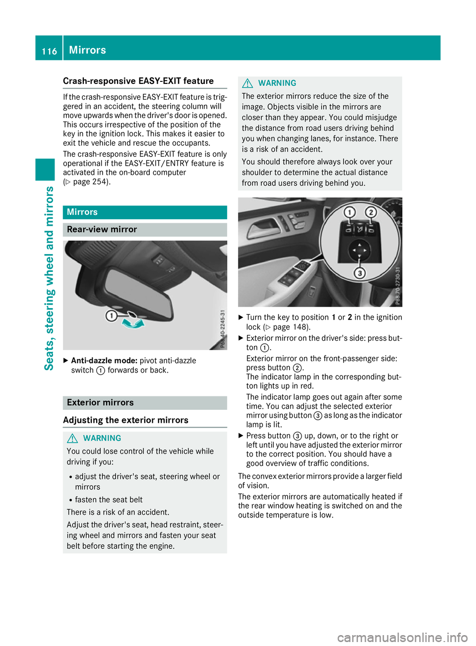
from road users driving behind you. X
Turn the key to position 1or 2in the ignition
lock (Y page 148).
X Exterior mirror on the driver's side: press but-
ton :.
Exterior mirror on the front-passenger side:
press button ;.
The indicator lamp in the corresponding but-
ton lights up in red.
The indicator lamp goes out again after some
time. You can adjust the selected exterior
mirror using button =as long as the indicator
lamp is lit.
X Press button =up, down, or to the right or
left until you have adjusted the exterior mirror to the correct position. You should have a
good overview of traffic conditions.
The convex exterior mirrors provide a larger field
of vision.
The exterior mirrors are automatically heated if
the rear window heating is switched on and the
outside temperature is low. 116
MirrorsSeats, steering wheel and
mirrors
Page 121 of 397
The rear-view mirror and the exterior mirror on
the driver's side automatically go into anti-daz-
zle mode if the following conditions are met
simultaneously:
R the ignition is switched on and
R incident light from headlamps strikes the sen-
sor in the rear-view mirror
The mirrors do not dip if reverse gear is engaged or if the interior lighting is switched on. Parking position of the exterior mirror
on the front-passenger side
Setting and storing the parking position You can set the front-passenger side exterior
mirror so that you can see the rear wheel on that side as soon as you engage reverse gear. You
can store this position.
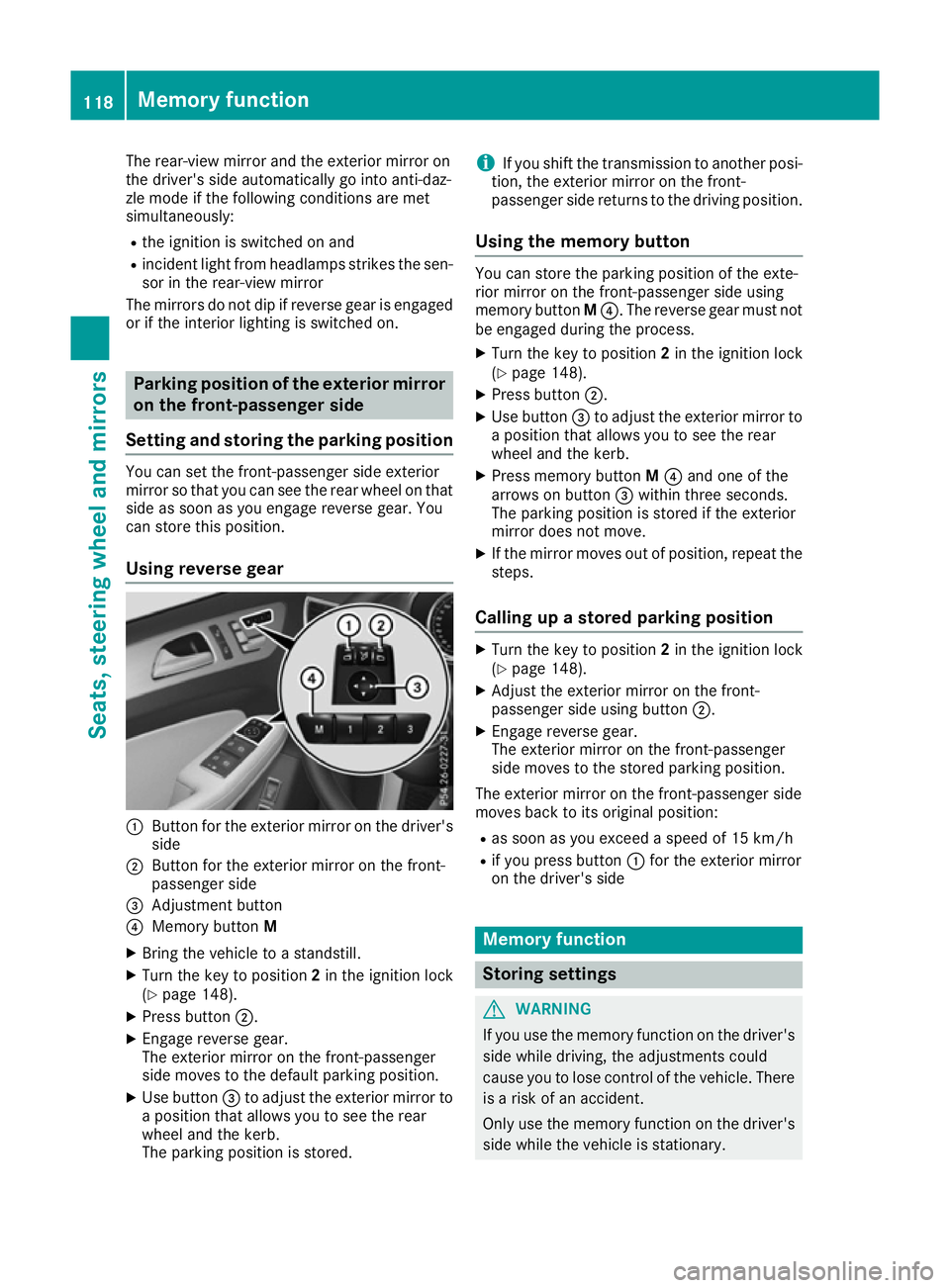
Using reverse gear :
Button for the exterior mirror on the driver's
side
; Button for the exterior mirror on the front-
passenger side
= Adjustment button
? Memory button M
X Bring the vehicle to a standstill.
X Turn the key to position 2in the ignition lock
(Y page 148).
X Press button ;.
X Engage reverse gear.
The exterior mirror on the front-passenger
side moves to the default parking position.
X Use button =to adjust the exterior mirror to
a position that allows you to see the rear
wheel and the kerb.
The parking position is stored. i
If you shift the transmission to another posi-
tion, the exterior mirror on the front-
passenger side returns to the driving position.
Using the memory button You can store the parking position of the exte-
rior mirror on the front-passenger side using
memory button
M?. The reverse gear must not
be engaged during the process.
X Turn the key to position 2in the ignition lock
(Y page 148).
X Press button ;.
X Use button =to adjust the exterior mirror to
a position that allows you to see the rear
wheel and the kerb.
X Press memory button M? and one of the
arrows on button =within three seconds.
The parking position is stored if the exterior
mirror does not move.
X If the mirror moves out of position, repeat the
steps.
Calling up a stored parking position X
Turn the key to position 2in the ignition lock
(Y page 148).
X Adjust the exterior mirror on the front-
passenger side using button ;.
X Engage reverse gear.
The exterior mirror on the front-passenger
side moves to the stored parking position.
The exterior mirror on the front-passenger side
moves back to its original position: R as soon as you exceed a speed of 15 km/h
R if you press button :for the exterior mirror
on the driver's side Memory function
Storing settings
G
WARNING
If you use the memory function on the driver's side while driving, the adjustments could
cause you to lose control of the vehicle. There
is a risk of an accident.
Only use the memory function on the driver's
side while the vehicle is stationary. 118
Memory functionSeats, steering wheel and mirrors
Page 211 of 397
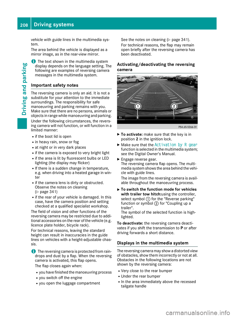
vehicle with guide lines in the multimedia sys-
tem.
The area behind the vehicle is displayed as a
mirror image, as in the rear-view mirror.
i The text shown in the multimedia system
display depends on the language setting. The following are examples of reversing camera
messages in the multimedia system.
Important safety notes The reversing camera is only an aid. It is not a
substitute for your attention to the immediate
surroundings. The responsibility for safe
manoeuvring and parking remains with you.
Make sure that there are no persons, animals or objects in range while manoeuvring and parking.
Under the following circumstances, the revers-
ing camera will not function, or will function in a limited manner:
R if the boot lid is open
R in heavy rain, snow or fog
R at night or in very dark places
R if the camera is exposed to very bright light
R if the area is lit by fluorescent bulbs or LED
lighting (the display may flicker)
R If there is a sudden change in temperature,
e.g. when driving into a heated garage in win- ter
R if the camera lens is dirty or obstructed.
Observe the notes on cleaning
(Y page 341)
R if the rear of your vehicle is damaged. In this
case, have the camera position and setting
checked at a qualified specialist workshop.
The field of vision and other functions of the
reversing camera may be restricted due to addi-
tional accessories on the rear of the vehicle (e.g. licence plate holder, bicycle rack).
For technical reasons, leaving the standard
height can result in inaccuracies in the guide
lines on vehicles with a height-adjustable chas-
sis.
i The reversing camera is protected from rain-
drops and dust by a flap. When the reversing
camera is activated, this flap opens.
The flap closes again when:
R you have finished the manoeuvring process
R you switch off the engine
R you open the luggage compartment See the notes on cleaning (Y
page 341).
For technical reasons, the flap may remain
open briefly after the reversing camera has
been deactivated.
Activating/deactivating the reversing
camera X
To activate: make sure that the key is in
position 2in the ignition lock.
X Make sure that the Activation by R gear Activation by R gear
function is selected in the multimedia system; see the Digital Owner's Manual.
X Engage reverse gear.
The reversing camera flap opens. The multi-
media system shows the area behind the vehi-
cle with guide lines.
The image from the reversing camera is avail-
able throughout the manoeuvring process.
X To switch the function mode for vehicles
with trailer tow hitch: using the controller,
select symbol :for the "Reverse parking"
function or symbol ;for "Coupling up a
trailer".
The symbol of the selected function is high-
lighted.
To deactivate: the reversing camera deacti-
vates if you shift the transmission to Por after
driving forwards a short distance.
Displays in the multimedia system The reversing camera may show a distorted view
of obstacles, show them incorrectly or not at all. Obstacles in the following locations are not
shown by the reversing camera:
R Very close to the rear bumper
R Under the rear bumper
R In the area immediately above the recessed
tailgate handle 208
Driving systemsDriving and parking
Page 215 of 397
only to objects that are at the same level as
the ball coupling.
X Reverse carefully, making sure that trailer
drawbar locating aid ;points approximately
in the direction of trailer drawbar =.
X Reverse carefully until trailer drawbar =rea-
ches the red guide line.
The distance between the trailer drawbar and
the red guide line is now approximately
0.30 m.
X Couple up the trailer (Y page 234).
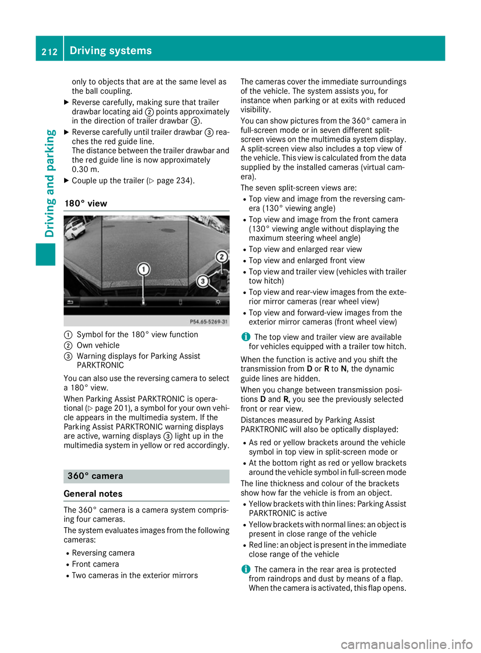
180° view :
Symbol for the 180° view function
; Own vehicle
= Warning displays for Parking Assist
PARKTRONIC
You can also use the reversing camera to select
a 180° view.
When Parking Assist PARKTRONIC is opera-
tional (Y page 201), a symbol for your own vehi-
cle appears in the multimedia system. If the
Parking Assist PARKTRONIC warning displays
are active, warning displays =light up in the
multimedia system in yellow or red accordingly. 360° camera
General notes The 360° camera is a camera system compris-
ing four cameras.
The system evaluates images from the following
cameras:
R Reversing camera
R Front camera
R Two cameras in the exterior mirrors The cameras cover the immediate surroundings
of the vehicle. The system assists you, for
instance when parking or at exits with reduced
visibility.
You can show pictures from the 360° camera in full-screen mode or in seven different split-
screen views on the multimedia system display. A split-screen view also includes a top view of
the vehicle. This view is calculated from the data
supplied by the installed cameras (virtual cam-
era).
The seven split-screen views are:
R Top view and image from the reversing cam-
era (130° viewing angle)
R Top view and image from the front camera
(130° viewing angle without displaying the
maximum steering wheel angle)
R Top view and enlarged rear view
R Top view and enlarged front view
R Top view and trailer view (vehicles with trailer
tow hitch)
R Top view and rear-view images from the exte-
rior mirror cameras (rear wheel view)
R Top view and forward-view images from the
exterior mirror cameras (front wheel view)
i The top view and trailer view are available
for vehicles equipped with a trailer tow hitch.
When the function is active and you shift the
transmission from Dor Rto N, the dynamic
guide lines are hidden.
When you change between transmission posi-
tions Dand R, you see the previously selected
front or rear view.
Distances measured by Parking Assist
PARKTRONIC will also be optically displayed:
R As red or yellow brackets around the vehicle
symbol in top view in split-screen mode or
R At the bottom right as red or yellow brackets
around the vehicle symbol in full-screen mode
The line thickness and colour of the brackets
show how far the vehicle is from an object.
R Yellow brackets with thin lines: Parking Assist
PARKTRONIC is active
R Yellow brackets with normal lines: an object is
present in close range of the vehicle
R Red line: an object is present in the immediate
close range of the vehicle
i The camera in the rear area is protected
from raindrops and dust by means of a flap.
When the camera is activated, this flap opens. 212
Driving systemsDriving and parking
Page 216 of 397
The flap closes again when:
R you have finished the manoeuvring process
R you switch off the engine
R you open the luggage compartment
See the notes on cleaning (Y page 341).
For technical reasons, the flap may remain
open briefly after the camera has been deac- tivated.
Important safety notes The 360° camera is only an aid and may show a
distorted view of obstacles, show them incor-
rectly or not at all. The 360° camera is not a
substitute for attentive driving.
The responsibility for safe manoeuvring and
parking remains with you. Make sure that there
are no persons, animals or objects in range
while manoeuvring and parking.
You are responsible for safety at all times and
must always pay attention to your surroundings when parking and manoeuvring. This applies to
the areas behind, in front of and beside the vehi- cle. You could otherwise endanger yourself and
others.
The 360° camera will not function or will func-
tion only to a limited extent:
R If the doors are open
R If the exterior mirrors are folded in
R If the tailgate is open
R In heavy rain, snow or fog
R At night or in very dark places
R If the cameras are exposed to very bright light
R If the area is lit by fluorescent bulbs or LED
lighting (the display may flicker)
R If there is a sudden change in temperature,
e.g. when driving into a heated garage in win- ter
R If the camera lenses are dirty or covered
R If the vehicle components in which the cam-
eras are fitted are damaged. In this event,
have the camera position and setting checked
at a qualified specialist workshop
Do not use the 360° camera under such cir-
cumstances. You could otherwise injure others
or damage objects when parking the vehicle.
Guide lines are always shown at road level. In
trailer mode, the guide lines are shown at the
level of the trailer coupling. The field of vision and other functions of the
camera system may be restricted due to addi-
tional accessories on the rear of the vehicle (e.g.
licence plate holder, bicycle rack).
On vehicles with height-adjustable suspension,
due to the technical conditions, leaving the
standard height can result in the following:
R Inaccuracies in the guide lines
R Inaccuracies in the display of generated
images (top view)
Activation conditions The 360° camera image can be displayed if:
R your vehicle is equipped with a 360° camera
R the key is in position 2in the ignition lock
R the multimedia system is switched on
Activating the 360° camera X
Press the Øbutton in the centre console
for longer than two seconds.
The following appears depending on whether transmission position Dor Ris selected:
R a split screen with top view and the image
from the front camera or
R a split screen with top view and the image
from the reversing camera
or
X Press the Øbutton in the centre console.
The vehicle menu appears.
X Select 360°
360° camera camera and press 7to confirm.
The following appears depending on whether transmission position Dor Ris selected:
R a split screen with top view and the image
from the front camera or
R a split screen with top view and the image
from the reversing camera
Switching on the 360° camera using
reverse gear You can show images from the 360° camera
automatically by engaging reverse gear. Driving systems
213Driving and parking Z
Page 217 of 397
X
Make sure that the key is in position 2in the
ignition lock.
X Make sure that the Activation by R gear
Activation by R gear
function is selected in the multimedia system (see the separate operating instructions).
X To show the 360° camera image: engage
reverse gear.
The multimedia system shows the area
behind the vehicle in split-screen mode. You
see the top view of the vehicle and the image from the reversing camera.
Selecting the split-screens or 180° view Selecting split-screen view
X To switch to the line with the vehicle icons:
slide 5the controller.
X To select one of the vehicle icons: turn 3
the controller.
X To switch to 180° view 180° view:turn 3 the con-
troller to select 180° view
180° view and press7to
confirm.
i The
180°
180° view
viewoption is only available in the
following views:
R Top view with image from the reversing
camera
R Top view with image from the front camera
Displays in the multimedia system Important safety notes
The camera system may show a distorted view
of obstacles or show them incorrectly or not at
all. Obstacles in the following locations are not
shown by the system:
R Under the front and rear bumpers
R Very close to the front and rear bumpers
R In the area immediately above the recessed
tailgate handle
R Very close to the exterior mirrors
R In the transitional areas between the various
cameras in the virtual top view
! Objects not at ground level may appear to
be further away than they actually are, e.g.:
R the bumper of a parked vehicle
R the drawbar of a trailer
R the ball coupling of a trailer tow hitch R
the rear section of an HGV
R a slanted post
Use the guidelines only for orientation.
Approach objects no further than the bottom- most guideline.
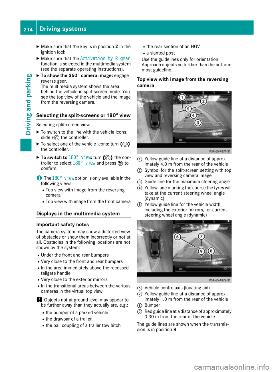
Top view with image from the reversing
camera :
Yellow guide line at a distance of approx-
imately 4.0 m from the rear of the vehicle
; Symbol for the split-screen setting with top
view and reversing camera image
= Guide line for the maximum steering angle
? Yellow lane marking the course the tyres will
take at the current steering wheel angle
(dynamic)
A Yellow guide line for the vehicle width
including the exterior mirrors, for current
steering wheel angle (dynamic) B
Vehicle centre axis (locating aid)
C Yellow guide line at a distance of approx-
imately 1.0 m from the rear of the vehicle
D Bumper
E Red guide line at a distance of approximately
0.30 m from the rear of the vehicle
The guide lines are shown when the transmis-
sion is in position R.214
Driving systemsDriving and parking