2016 MERCEDES-BENZ GLC COUPE check engine
[x] Cancel search: check enginePage 201 of 389
A warning tone sounds. The parking symbol dis-
appears and the multifunction display shows the
Park Assist cancelled
Park Assist cancelled message.
When Active Parking Assist is cancelled, you
must steer and brake again yourself.
If a system malfunction occurs, the vehicle is
braked to a standstill. To drive on, depress the
accelerator pedal again. Reversing camera
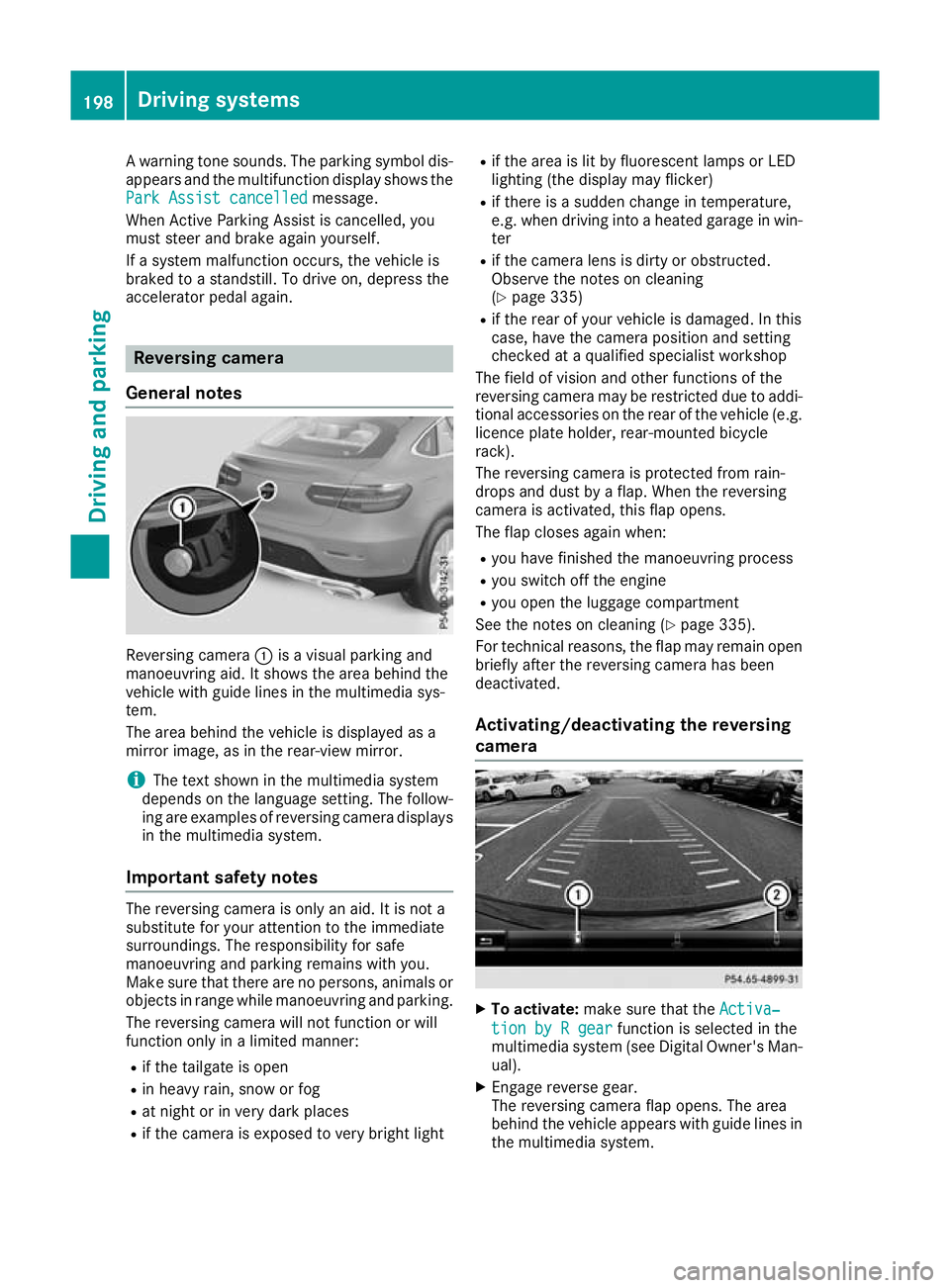
General notes Reversing camera
:is a visual parking and
manoeuvring aid. It shows the area behind the
vehicle with guide lines in the multimedia sys-
tem.
The area behind the vehicle is displayed as a
mirror image, as in the rear-view mirror.
i The text shown in the multimedia system
depends on the language setting. The follow- ing are examples of reversing camera displays
in the multimedia system.
Important safety notes The reversing camera is only an aid. It is not a
substitute for your attention to the immediate
surroundings. The responsibility for safe
manoeuvring and parking remains with you.
Make sure that there are no persons, animals or
objects in range while manoeuvring and parking.
The reversing camera will not function or will
function only in a limited manner:
R if the tailgate is open
R in heavy rain, snow or fog
R at night or in very dark places
R if the camera is exposed to very bright light R
if the area is lit by fluorescent lamps or LED
lighting (the display may flicker)
R if there is a sudden change in temperature,
e.g. when driving into a heated garage in win-
ter
R if the camera lens is dirty or obstructed.
Observe the notes on cleaning
(Y page 335)
R if the rear of your vehicle is damaged. In this
case, have the camera position and setting
checked at a qualified specialist workshop
The field of vision and other functions of the
reversing camera may be restricted due to addi-
tional accessories on the rear of the vehicle (e.g. licence plate holder, rear-mounted bicycle
rack).
The reversing camera is protected from rain-
drops and dust by a flap. When the reversing
camera is activated, this flap opens.
The flap closes again when:
R you have finished the manoeuvring process
R you switch off the engine
R you open the luggage compartment
See the notes on cleaning (Y page 335).
For technical reasons, the flap may remain open
briefly after the reversing camera has been
deactivated.
Activating/deactivating the reversing
camera X
To activate: make sure that the Activa‐ Activa‐
tion by R gear
tion by R gear function is selected in the
multimedia system (see Digital Owner's Man-
ual).
X Engage reverse gear.
The reversing camera flap opens. The area
behind the vehicle appears with guide lines in the multimedia system. 198
Driving systemsDriving an
d parking
Page 214 of 389
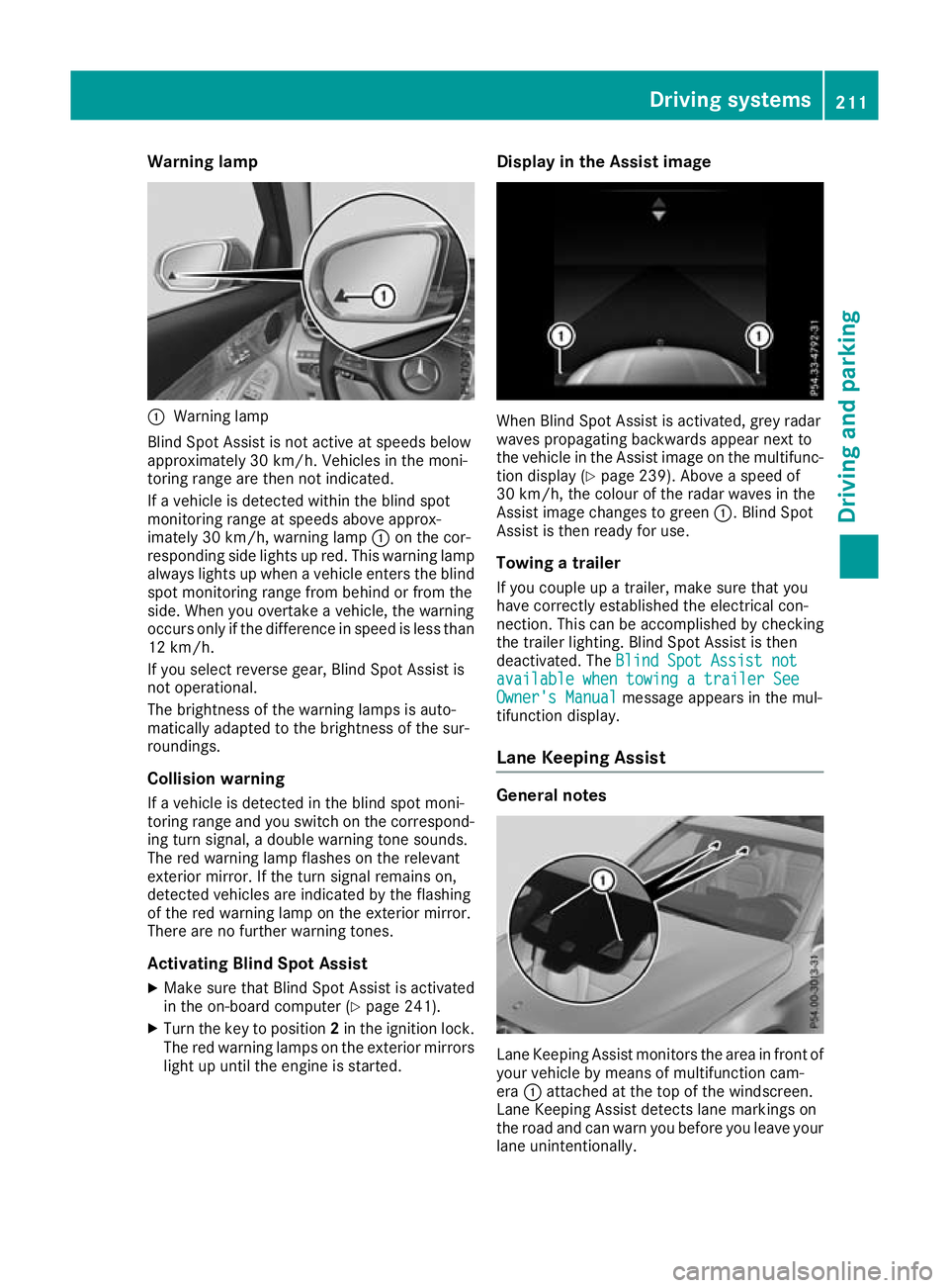
Warning lamp
:
Warning lamp
Blind Spot Assist is not active at speeds below
approximately 30 km/h. Vehicles in the moni-
toring range are then not indicated.
If a vehicle is detected within the blind spot
monitoring range at speeds above approx-
imately 30 km/h, warning lamp :on the cor-
responding side lights up red. This warning lamp always lights up when a vehicle enters the blindspot monitoring range from behind or from the
side. When you overtake a vehicle, the warning
occurs only if the difference in speed is less than
12 km/h.
If you select reverse gear, Blind Spot Assist is
not operational.
The brightness of the warning lamps is auto-
matically adapted to the brightness of the sur-
roundings.
Collision warning
If a vehicle is detected in the blind spot moni-
toring range and you switch on the correspond-
ing turn signal, a double warning tone sounds.
The red warning lamp flashes on the relevant
exterior mirror. If the turn signal remains on,
detected vehicles are indicated by the flashing
of the red warning lamp on the exterior mirror.
There are no further warning tones.
Activating Blind Spot Assist
X Make sure that Blind Spot Assist is activated
in the on-board computer (Y page 241).
X Turn the key to position 2in the ignition lock.
The red warning lamps on the exterior mirrors
light up until the engine is started. Display in the Assist image
When Blind Spot Assist is activated, grey radar
waves propagating backwards appear next to
the vehicle in the Assist image on the multifunc-
tion display (Y page 239). Above a speed of
30 km/h, the colour of the radar waves in the
Assist image changes to green :. Blind Spot
Assist is then ready for use.
Towing a trailer
If you couple up a trailer, make sure that you
have correctly established the electrical con-
nection. This can be accomplished by checking
the trailer lighting. Blind Spot Assist is then
deactivated. The Blind Spot Assist not Blind Spot Assist not
available when towing a trailer See
available when towing a trailer See
Owner's Manual Owner's Manual message appears in the mul-
tifunction display.
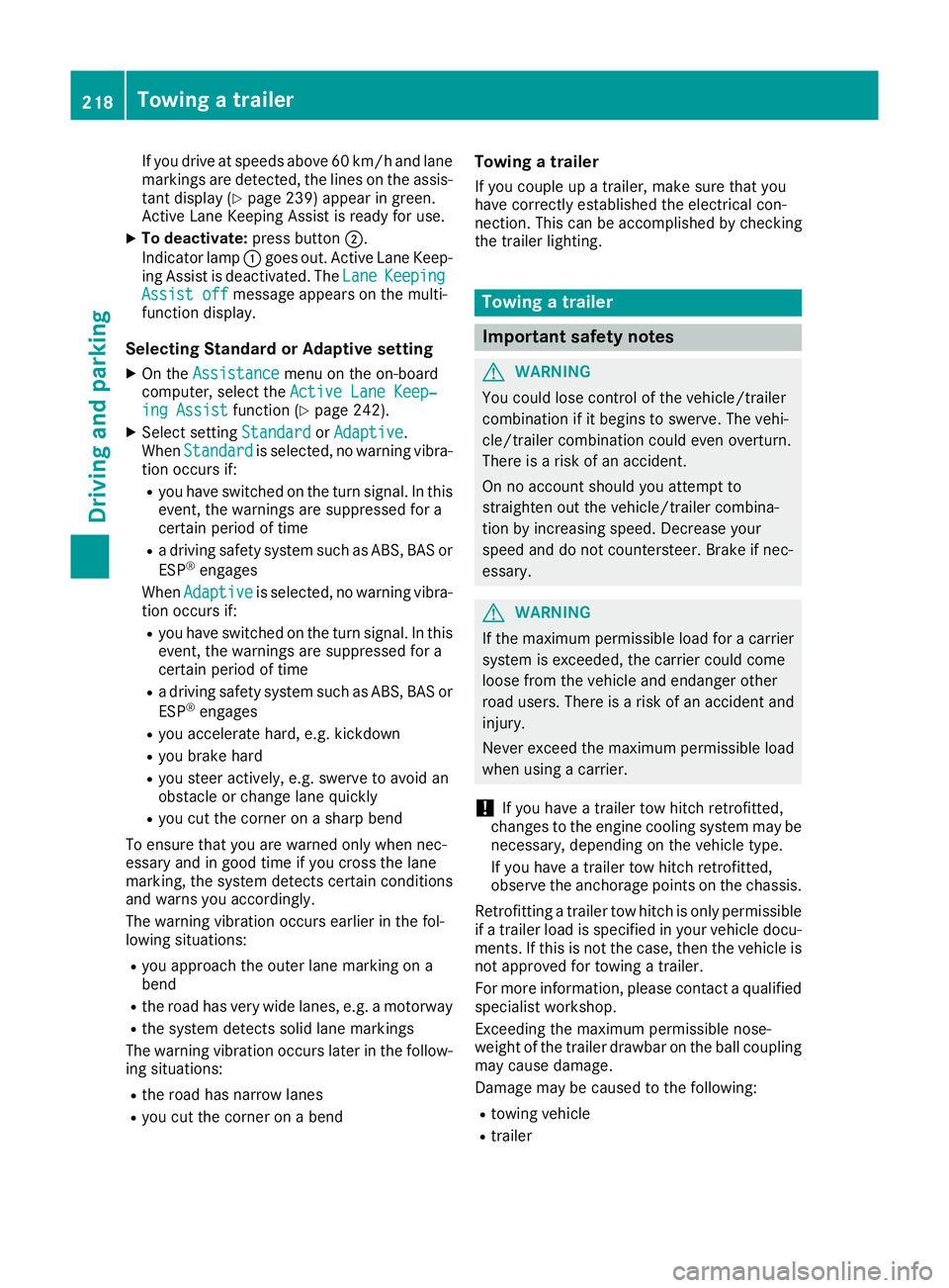
Lane Keeping Assist General notes
Lane Keeping Assist monitors the area in front of
your vehicle by means of multifunction cam-
era :attached at the top of the windscreen.
Lane Keeping Assist detects lane markings on
the road and can warn you before you leave your lane unintentionally. Driving systems
211Driving and parking Z
Page 221 of 389
If you drive at speeds above 60 km/h and lane
markings are detected, the lines on the assis- tant display (Y page 239) appear in green.
Active Lane Keeping Assist is ready for use.
X To deactivate: press button;.
Indicator lamp :goes out. Active Lane Keep-
ing Assist is deactivated. The Lane
Lane Keeping
Keeping
Assist off
Assist off message appears on the multi-
function display.
Selecting Standard or Adaptive setting X On the Assistance
Assistance menu on the on-board
computer, select the Active Lane Keep‐
Active Lane Keep‐
ing Assist
ing Assist function (Ypage 242).
X Select setting Standard
StandardorAdaptive
Adaptive.
When Standard
Standard is selected, no warning vibra-
tion occurs if:
R you have switched on the turn signal. In this
event, the warnings are suppressed for a
certain period of time
R a driving safety system such as ABS, BAS or
ESP ®
engages
When Adaptive Adaptive is selected, no warning vibra-
tion occurs if:
R you have switched on the turn signal. In this
event, the warnings are suppressed for a
certain period of time
R a driving safety system such as ABS, BAS or
ESP ®
engages
R you accelerate hard, e.g. kickdown
R you brake hard
R you steer actively, e.g. swerve to avoid an
obstacle or change lane quickly
R you cut the corner on a sharp bend
To ensure that you are warned only when nec-
essary and in good time if you cross the lane
marking, the system detects certain conditions
and warns you accordingly.
The warning vibration occurs earlier in the fol-
lowing situations:
R you approach the outer lane marking on a
bend
R the road has very wide lanes, e.g. a motorway
R the system detects solid lane markings
The warning vibration occurs later in the follow- ing situations:
R the road has narrow lanes
R you cut the corner on a bend Towing a trailer
If you couple up a trailer, make sure that you
have correctly established the electrical con-
nection. This can be accomplished by checking
the trailer lighting. Towing a trailer
Important safety notes
G
WARNING
You could lose control of the vehicle/trailer
combination if it begins to swerve. The vehi-
cle/trailer combination could even overturn.
There is a risk of an accident.
On no account should you attempt to
straighten out the vehicle/trailer combina-
tion by increasing speed. Decrease your
speed and do not countersteer. Brake if nec-
essary. G
WARNING
If the maximum permissible load for a carrier system is exceeded, the carrier could come
loose from the vehicle and endanger other
road users. There is a risk of an accident and injury.
Never exceed the maximum permissible load
when using a carrier.
! If you have a trailer tow hitch retrofitted,
changes to the engine cooling system may be necessary, depending on the vehicle type.
If you have a trailer tow hitch retrofitted,
observe the anchorage points on the chassis.
Retrofitting a trailer tow hitch is only permissible
if a trailer load is specified in your vehicle docu-
ments. If this is not the case, then the vehicle is not approved for towing a trailer.
For more information, please contact a qualifiedspecialist workshop.
Exceeding the maximum permissible nose-
weight of the trailer drawbar on the ball coupling
may cause damage.
Damage may be caused to the following:
R towing vehicle
R trailer 218
Towing a trailerDriving and parking
Page 225 of 389
Coupling up a trailer
X Apply the electric parking brake manually.
X Shift the transmission to position P.
X Position the trailer on a level surface behind
the vehicle.
X Couple up the trailer.
X Establish the electrical connection between
the vehicle and the trailer.
X Check that the trailer lighting system is work-
ing.
X Push the combination switch upwards and
downwards and check whether the corre-
sponding turn signal indicator on the trailer is
flashing.
A connected trailer is only detected when the
electrical connection is established correctly
and the lighting system is working properly. The
function of other systems also depends on this, for example:
R ESP ®
R PARKTRONIC
R Active Parking Assist
R Active Blind Spot Assist
R Active Lane Keeping Assist Uncoupling a trailer
G
WARNING
If you uncouple a trailer with an engaged over- run brake, you could trap your hand between
the vehicle and the trailer drawbar. This poses a risk of injury.
Do not uncouple a trailer with an engaged
overrun brake. G
WARNING
Vehicles with level control:
If you disconnect the trailer cable, the vehicle is lowered. This can cause you or others to
become trapped between the vehicle body
and tyres, or underneath the vehicle. This
poses a risk of injury.
Make sure that no-one is in the immediate
vicinity of the wheel arch or underneath the
vehicle when disconnecting the trailer cable. !
Do not disconnect a trailer with an engaged
overrun brake. Otherwise, your vehicle could
be damaged by the rebounding of the overrun
brake.
! Remove the adapter cable before folding in
the ball coupling. You could otherwise dam-
age the rear bumper and the adapter cable.
X Apply the electric parking brake manually.
X Shift the transmission to position P.
X Switch off the engine.
X Secure the vehicle and trailer against rolling
away.
X Remove the trailer cable and uncouple the
trailer. Trailer power supply
! Accessories with a maximum power con-
sumption of 180 W can be connected to the
permanent power supply.
The trailer battery may not be charged from
the power supply.
When it leaves the factory, your vehicle's trailer
socket is equipped with a permanent power
supply and a power supply that is switched on
via the ignition lock.
The permanent power supply is supplied via
trailer socket pin 9.
The power supply that is switched on via the
ignition lock is supplied via trailer socket pin 10.
The trailer's permanent power supply is
switched off in the event of low on-board voltage
and after six hours at the latest.
You can find more information about installing
the trailer electrics at a qualified specialist work- shop.
To activate the switched power supply:
X Turn the key to position 2in the ignition lock
(Y page 144).
or
X Press the Start/Stop button twice on vehicles
with KEYLESS-GO or the KEYLESS-GO start
function (Y page 144).222
Towing a trailerDriving and parking
Page 227 of 389
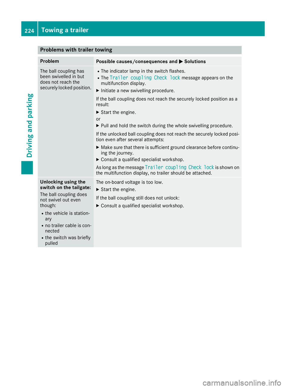
Problems with trailer towing
Problem
Possible causes/consequences and
M
MSolutions The ball coupling has
been swivelled in but
does not reach the
securely locked position. R
The indicator lamp in the switch flashes.
R The Trailer coupling Check lock Trailer coupling Check lock message appears on the
multifunction display.
X Initiate a new swivelling procedure.
If the ball coupling does not reach the securely locked position as a
result: X Start the engine.
or
X Pull and hold the switch during the whole swivelling procedure.
If the unlocked ball coupling does not reach the securely locked posi- tion even after several attempts:
X Make sure that there is sufficient ground clearance before continu-
ing the journey.
X Consult a qualified specialist workshop.
As long as the message Trailer Trailercoupling
coupling Check
Checklock
lockis shown on
the multifunction display, no trailer should be attached. Unlocking using the
switch on the tailgate:
The ball coupling does
not swivel out even
though:
R the vehicle is station-
ary
R no trailer cable is con-
nected
R the switch was briefly
pulled The on-board voltage is too low.
X Start the engine.
If the ball coupling still does not unlock:
X Consult a qualified specialist workshop. 224
Towing a trailerDriving and parking
Page 228 of 389
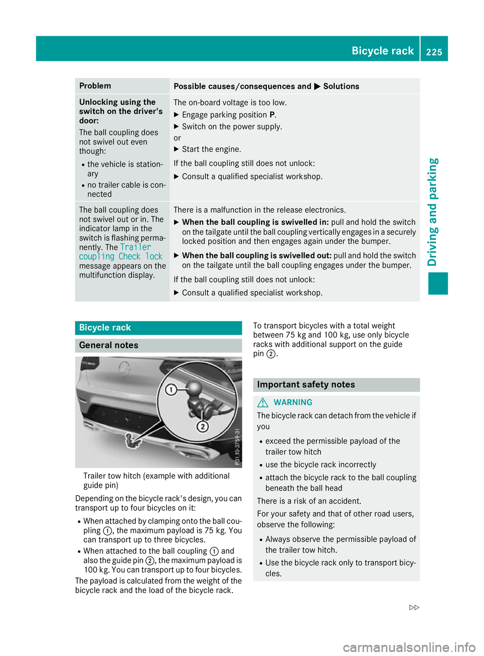
Problem
Possible causes/consequences and
M
MSolutions Unlocking using the
switch on the driver's
door:
The ball coupling does
not swivel out even
though:
R the vehicle is station-
ary
R no trailer cable is con-
nected The on-board voltage is too low.
X Engage parking position P.
X Switch on the power supply.
or X Start the engine.
If the ball coupling still does not unlock: X Consult a qualified specialist workshop. The ball coupling does
not swivel out or in. The
indicator lamp in the
switch is flashing perma-
nently. The Trailer Trailer
coupling Check lock
coupling Check lock
message appears on the
multifunction display. There is a malfunction in the release electronics.
X When the ball coupling is swivelled in: pull and hold the switch
on the tailgate until the ball coupling vertically engages in a securely locked position and then engages again under the bumper.
X When the ball coupling is swivelled out: pull and hold the switch
on the tailgate until the ball coupling engages under the bumper.
If the ball coupling still does not unlock: X Consult a qualified specialist workshop. Bicycle rack
General notes
Trailer tow hitch (example with additional
guide pin)
Depending on the bicycle rack's design, you can transport up to four bicycles on it:
R When attached by clamping onto the ball cou-
pling :, the maximum payload is 75 kg. You
can transport up to three bicycles.
R When attached to the ball coupling :and
also the guide pin ;, the maximum payload is
100 kg. You can transport up to four bicycles.
The payload is calculated from the weight of the
bicycle rack and the load of the bicycle rack. To transport bicycles with a total weight
between 75 kg and 100 kg, use only bicycle
racks with additional support on the guide
pin
;. Important safety notes
G
WARNING
The bicycle rack can detach from the vehicle if
you
R exceed the permissible payload of the
trailer tow hitch
R use the bicycle rack incorrectly
R attach the bicycle rack to the ball coupling
beneath the ball head
There is a risk of an accident.
For your safety and that of other road users,
observe the following:
R Always observe the permissible payload of
the trailer tow hitch.
R Use the bicycle rack only to transport bicy-
cles. Bicycle rack
225Driving and parking
Z
Page 243 of 389
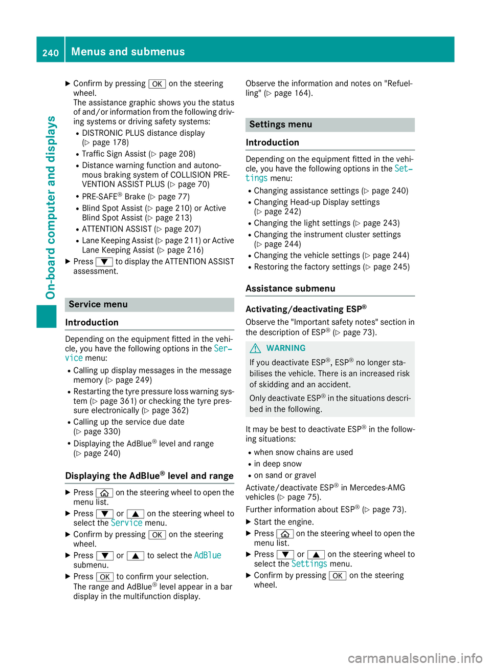
X
Confirm by pressing aon the steering
wheel.
The assistance graphic shows you the status
of and/or information from the following driv-
ing systems or driving safety systems:
R DISTRONIC PLUS distance display
(Y page 178)
R Traffic Sign Assist (Y page 208)
R Distance warning function and autono-
mous braking system of COLLISION PRE-
VENTION ASSIST PLUS (Y page 70)
R PRE-SAFE ®
Brake (Y page 77)
R Blind Spot Assist (Y page 210) or Active
Blind Spot Assist (Y page 213)
R ATTENTION ASSIST (Y page 207)
R Lane Keeping Assist (Y page 211) or Active
Lane Keeping Assist (Y page 216)
X Press :to display the ATTENTION ASSIST
assessment. Service menu
Introduction Depending on the equipment fitted in the vehi-
cle, you have the following options in the Ser‐
Ser‐
vice
vice menu:
R Calling up display messages in the message
memory (Y page 249)
R Restarting the tyre pressure loss warning sys-
tem (Y page 361) or checking the tyre pres-
sure electronically (Y page 362)
R Calling up the service due date
(Y page 330)
R Displaying the AdBlue ®
level and range
(Y page 240)
Displaying the AdBlue ®
level and range X
Press òon the steering wheel to open the
menu list.
X Press :or9 on the steering wheel to
select the Service
Service menu.
X Confirm by pressing aon the steering
wheel.
X Press :or9 to select the AdBlue AdBlue
submenu.
X Press ato confirm your selection.
The range and AdBlue ®
level appear in a bar
display in the multifunction display. Observe the information and notes on "Refuel-
ling" (Y
page 164). Settings menu
Introduction Depending on the equipment fitted in the vehi-
cle, you have the following options in the
Set‐ Set‐
tings
tings menu:
R Changing assistance settings (Y page 240)
R Changing Head-up Display settings
(Y page 242)
R Changing the light settings (Y page 243)
R Changing the instrument cluster settings
(Y page 244)
R Changing the vehicle settings (Y page 244)
R Restoring the factory settings (Y page 245)
Assistance submenu Activating/deactivating ESP
®
Observe the "Important safety notes" section in the description of ESP ®
(Y page 73). G
WARNING
If you deactivate ESP ®
, ESP ®
no longer sta-
bilises the vehicle. There is an increased risk
of skidding and an accident.
Only deactivate ESP ®
in the situations descri-
bed in the following.
It may be best to deactivate ESP ®
in the follow-
ing situations:
R when snow chains are used
R in deep snow
R on sand or gravel
Activate/deactivate ESP ®
in Mercedes-AMG
vehicles (Y page 75).
Further information about ESP ®
(Y page 73).
X Start the engine.
X Press òon the steering wheel to open the
menu list.
X Press :or9 on the steering wheel to
select the Settings
Settings menu.
X Confirm by pressing aon the steering
wheel. 240
Menus and submenusOn-board computer and displays
Page 257 of 389
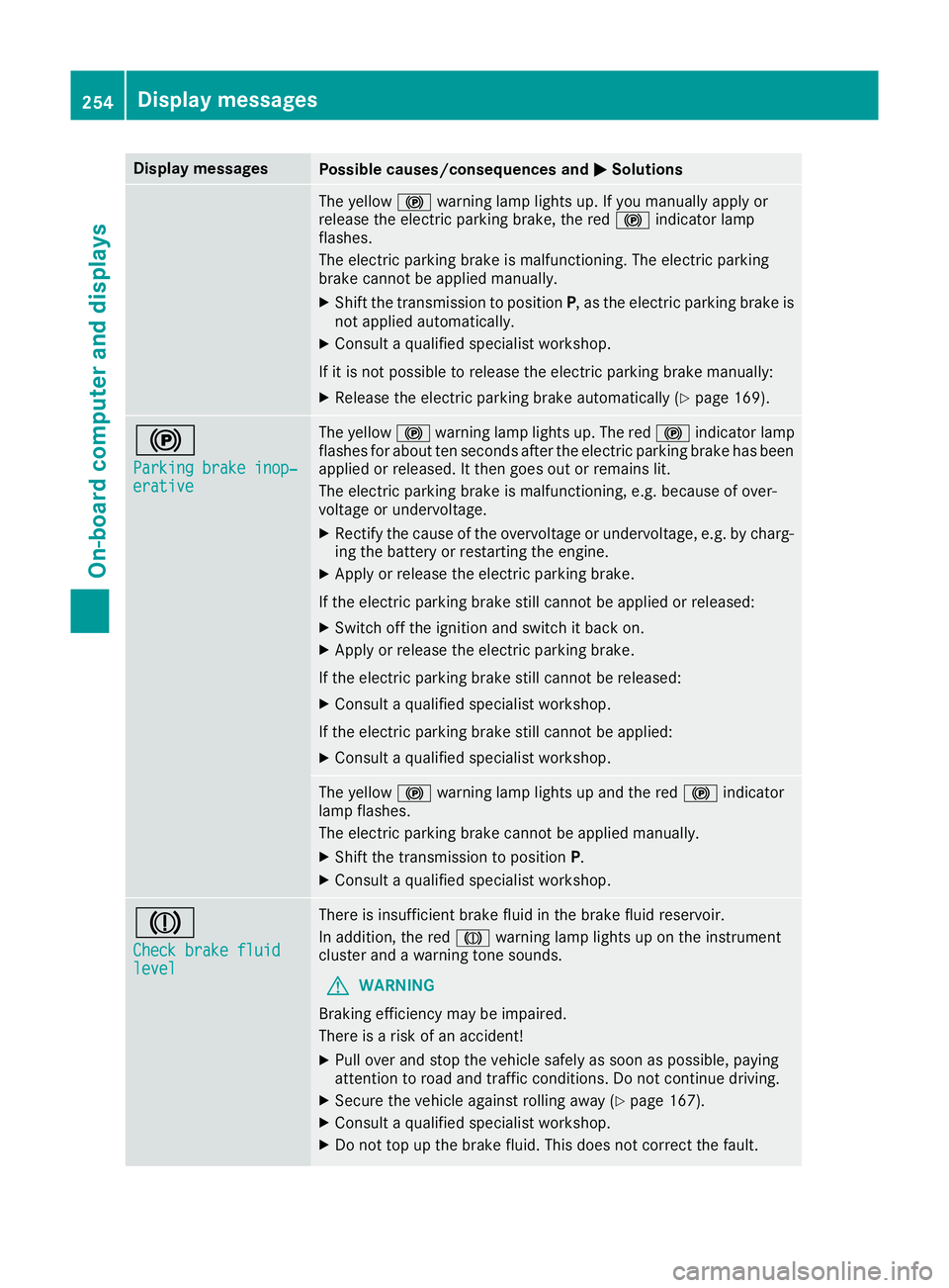
Display messages
Possible causes/consequences and
M
MSolutions The yellow
!warning lamp lights up. If you manually apply or
release the electric parking brake, the red !indicator lamp
flashes.
The electric parking brake is malfunctioning. The electric parking
brake cannot be applied manually.
X Shift the transmission to position P, as the electric parking brake is
not applied automatically.
X Consult a qualified specialist workshop.
If it is not possible to release the electric parking brake manually:
X Release the electric parking brake automatically (Y page 169).!
Parking brake inop‐ Parking brake inop‐
erative erative The yellow
!warning lamp lights up. The red !indicator lamp
flashes for about ten seconds after the electric parking brake has been applied or released. It then goes out or remains lit.
The electric parking brake is malfunctioning, e.g. because of over-
voltage or undervoltage.
X Rectify the cause of the overvoltage or undervoltage, e.g. by charg-
ing the battery or restarting the engine.
X Apply or release the electric parking brake.
If the electric parking brake still cannot be applied or released: X Switch off the ignition and switch it back on.
X Apply or release the electric parking brake.
If the electric parking brake still cannot be released: X Consult a qualified specialist workshop.
If the electric parking brake still cannot be applied:
X Consult a qualified specialist workshop. The yellow
!warning lamp lights up and the red !indicator
lamp flashes.
The electric parking brake cannot be applied manually.
X Shift the transmission to position P.
X Consult a qualified specialist workshop. J
Check brake fluid Check brake fluid
level level There is insufficient brake fluid in the brake fluid reservoir.
In addition, the red Jwarning lamp lights up on the instrument
cluster and a warning tone sounds.
G WARNING
Braking efficiency may be impaired.
There is a risk of an accident!
X Pull over and stop the vehicle safely as soon as possible, paying
attention to road and traffic conditions. Do not continue driving.
X Secure the vehicle against rolling away (Y page 167).
X Consult a qualified specialist workshop.
X Do not top up the brake fluid. This does not correct the fault. 254
Display
messagesOn-board computer and displays