2016 MERCEDES-BENZ GLC COUPE lock
[x] Cancel search: lockPage 312 of 389
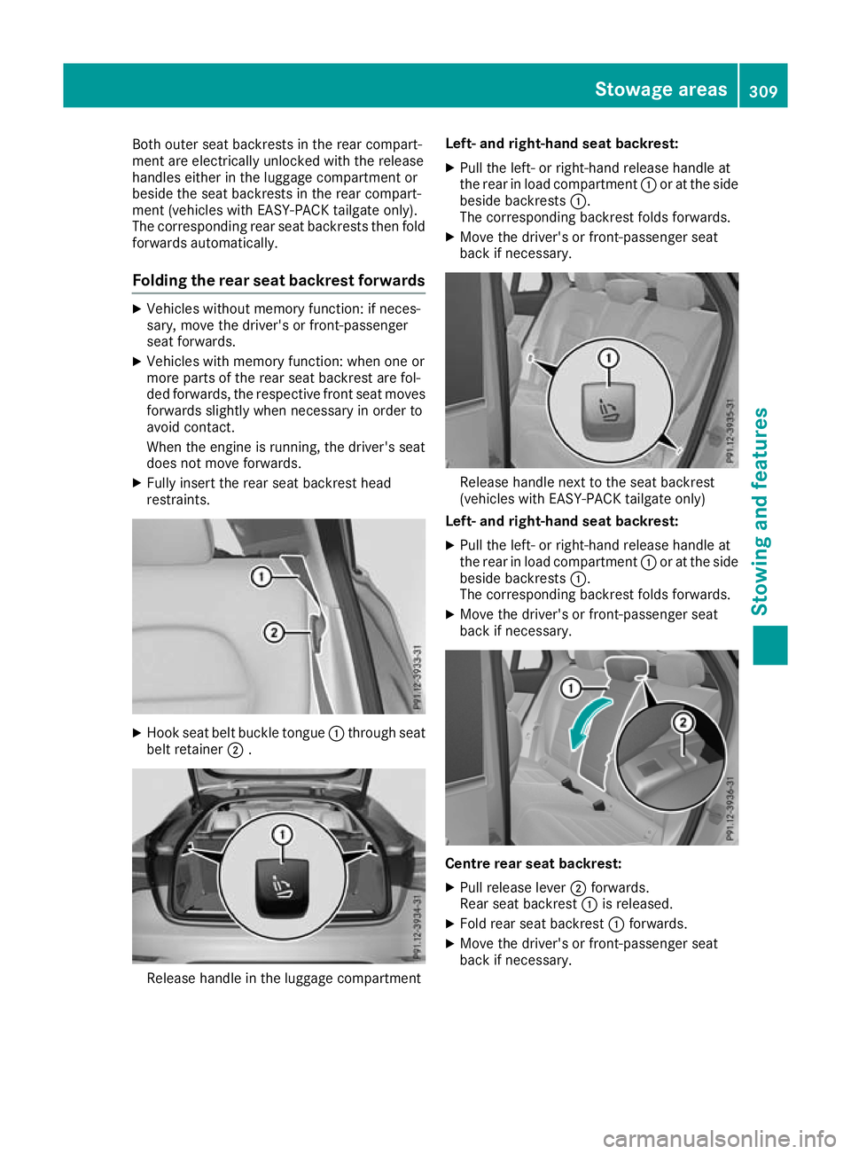
Both outer seat backrests in the rear compart-
ment are electrically unlocked with the release
handles either in the luggage compartment or
beside the seat backrests in the rear compart-
ment (vehicles with EASY-PACK tailgate only).
The corresponding rear seat backrests then fold forwards automatically.
Folding the rear seat backrest forwards X
Vehicles without memory function: if neces-
sary, move the driver's or front-passenger
seat forwards.
X Vehicles with memory function: when one or
more parts of the rear seat backrest are fol-
ded forwards, the respective front seat moves
forwards slightly when necessary in order to
avoid contact.
When the engine is running, the driver's seat
does not move forwards.
X Fully insert the rear seat backrest head
restraints. X
Hook seat belt buckle tongue :through seat
belt retainer ;. Release handle in the luggage compartment Left- and right-hand seat backrest:
X Pull the left- or right-hand release handle at
the rear in load compartment :or at the side
beside backrests :.
The corresponding backrest folds forwards.
X Move the driver's or front-passenger seat
back if necessary. Release handle next to the seat backrest
(vehicles with EASY-PACK tailgate only)
Left- and right-hand seat backrest:
X Pull the left- or right-hand release handle at
the rear in load compartment :or at the side
beside backrests :.
The corresponding backrest folds forwards.
X Move the driver's or front-passenger seat
back if necessary. Centre rear seat backrest:
X Pull release lever ;forwards.
Rear seat backrest :is released.
X Fold rear seat backrest :forwards.
X Move the driver's or front-passenger seat
back if necessary. Stowage areas
309Stowing and features Z
Page 313 of 389
Folding the rear seat backrest back
!
Make sure that the seat belt does not
become trapped when folding the rear seat
backrest back. Otherwise, it could be dam-
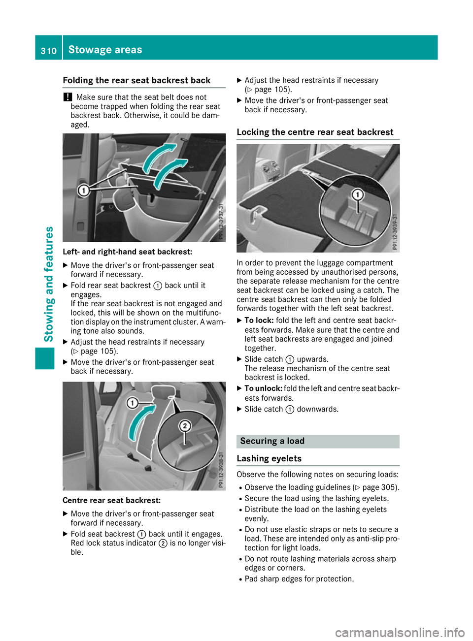
aged. Left- and right-hand seat backrest:
X Move the driver's or front-passenger seat
forward if necessary.
X Fold rear seat backrest :back until it
engages.
If the rear seat backrest is not engaged and
locked, this will be shown on the multifunc-
tion display on the instrument cluster. A warn- ing tone also sounds.
X Adjust the head restraints if necessary
(Y page 105).
X Move the driver's or front-passenger seat
back if necessary. Centre rear seat backrest:
X Move the driver's or front-passenger seat
forward if necessary.
X Fold seat backrest :back until it engages.
Red lock status indicator ;is no longer visi-
ble. X
Adjust the head restraints if necessary
(Y page 105).
X Move the driver's or front-passenger seat
back if necessary.
Locking the centre rear seat backrest In order to prevent the luggage compartment
from being accessed by unauthorised persons,
the separate release mechanism for the centre
seat backrest can be locked using a catch. The
centre seat backrest can then only be folded
forwards together with the left seat backrest.
X To lock: fold the left and centre seat backr-
ests forwards. Make sure that the centre and left seat backrests are engaged and joined
together.
X Slide catch :upwards.
The release mechanism of the centre seat
backrest is locked.
X To unlock: fold the left and centre seat backr-
ests forwards.
X Slide catch :downwards. Securing a load
Lashing eyelets Observe the following notes on securing loads:
R Observe the loading guidelines (Y page 305).
R Secure the load using the lashing eyelets.
R Distribute the load on the lashing eyelets
evenly.
R Do not use elastic straps or nets to secure a
load. These are intended only as anti-slip pro-
tection for light loads.
R Do not route lashing materials across sharp
edges or corners.
R Pad sharp edges for protection. 310
Stowage areasStowing and featu
res
Page 316 of 389
X
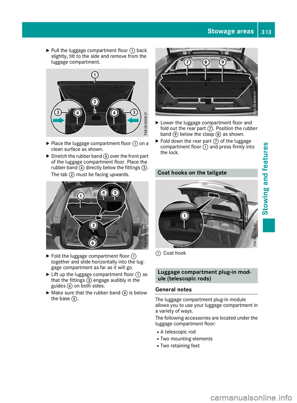
Pull the luggage compartment floor :back
slightly, tilt to the side and remove from the
luggage compartment. X
Place the luggage compartment floor :on a
clean surface as shown.
X Stretch the rubber band ?over the front part
of the luggage compartment floor. Place the
rubber band ?directly below the fittings =.
The tab ;must be facing upwards. X
Fold the luggage compartment floor :
together and slide horizontally into the lug-
gage compartment as far as it will go.
X Lift up the luggage compartment floor :so
that the fittings =engage audibly in the
guides Bon both sides.
X Make sure that the rubber band ?is below
the base A. X
Lower the luggage compartment floor and
fold out the rear part C. Position the rubber
band Ebelow the clasp Das shown.
X Fold down the rear part Cof the luggage
compartment floor :and press firmly into
the lock. Coat hooks on the tailgate
:
Coat hook Luggage compartment plug-in mod-
ule (telescopic rods)
General notes The luggage compartment plug-in module
allows you to use your luggage compartment in
a variety of ways.
The following accessories are located under the
luggage compartment floor:
R A telescopic rod
R Two mounting elements
R Two retaining feet Stowage areas
313Stowing and features Z
Page 318 of 389
X
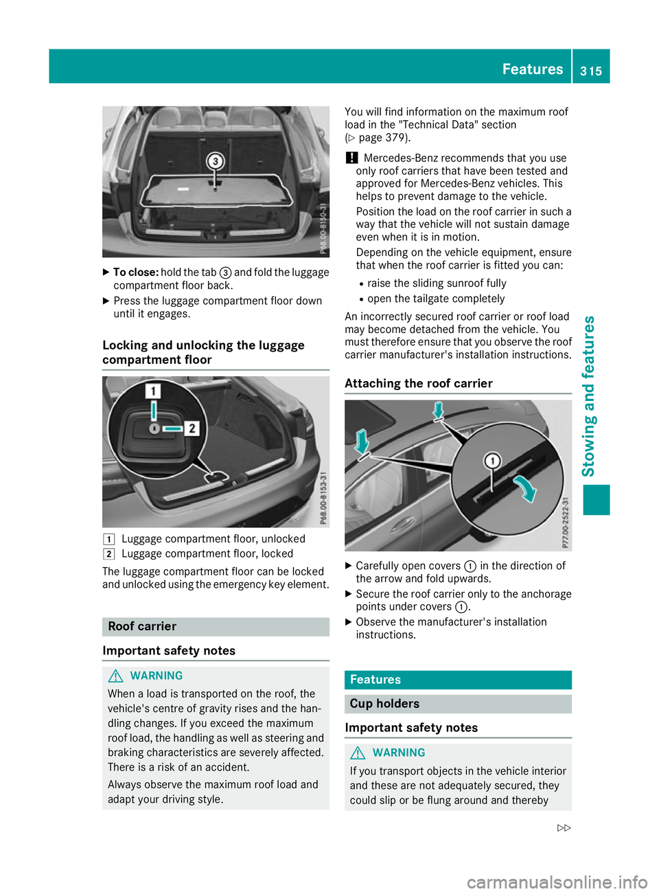
To close: hold the tab =and fold the luggage
compartment floor back.
X Press the luggage compartment floor down
until it engages.
Locking and unlocking the luggage
compartment floor 1
Luggage compartment floor, unlocked
2 Luggage compartment floor, locked
The luggage compartment floor can be locked
and unlocked using the emergency key element. Roof carrier
Important safety notes G
WARNING
When a load is transported on the roof, the
vehicle's centre of gravity rises and the han-
dling changes. If you exceed the maximum
roof load, the handling as well as steering and braking characteristics are severely affected.
There is a risk of an accident.
Always observe the maximum roof load and
adapt your driving style. You will find information on the maximum roof
load in the "Technical Data" section
(Y
page 379).
! Mercedes-Benz recommends that you use
only roof carriers that have been tested and
approved for Mercedes-Benz vehicles. This
helps to prevent damage to the vehicle.
Position the load on the roof carrier in such a way that the vehicle will not sustain damage
even when it is in motion.
Depending on the vehicle equipment, ensure
that when the roof carrier is fitted you can:
R raise the sliding sunroof fully
R open the tailgate completely
An incorrectly secured roof carrier or roof load
may become detached from the vehicle. You
must therefore ensure that you observe the roof carrier manufacturer's installation instructions.
Attaching the roof carrier X
Carefully open covers :in the direction of
the arrow and fold upwards.
X Secure the roof carrier only to the anchorage
points under covers :.
X Observe the manufacturer's installation
instructions. Features
Cup holders
Important safety notes G
WARNING
If you transport objects in the vehicle interior and these are not adequately secured, they
could slip or be flung around and thereby Features
315Stowing an d features
Z
Page 321 of 389
i
You can remove the ashtray insert and use
the resultant compartment for stowage.
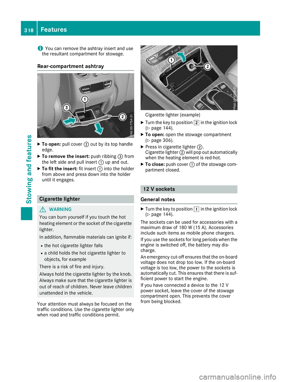
Rear-compartment ashtray X
To open: pull cover ;out by its top handle
edge.
X To remove the insert: push ribbing=from
the left side and pull insert :up and out.
X To fit the insert: fit insert:into the holder
from above and press down into the holder
until it engages. Cigarette lighter
G
WARNING
You can burn yourself if you touch the hot
heating element or the socket of the cigarette lighter.
In addition, flammable materials can ignite if:
R the hot cigarette lighter falls
R a child holds the hot cigarette lighter to
objects, for example
There is a risk of fire and injury.
Always hold the cigarette lighter by the knob.
Always make sure that the cigarette lighter is
out of reach of children. Never leave children unattended in the vehicle.
Your attention must always be focused on the
traffic conditions. Use the cigarette lighter only when road and traffic conditions permit. Cigarette lighter (example)
X Turn the key to position 2in the ignition lock
(Y page 144).
X To open: open the stowage compartment
(Y page 306).
X Press in cigarette lighter ;.
Cigarette lighter ;will pop out automatically
when the heating element is red-hot.
X To close: push cover :of the stowage com-
partment closed. 12 V sockets
General notes X
Turn the key to position 1in the ignition lock
(Y page 144).
The sockets can be used for accessories with a
maximum draw of 180 W (15 A). Accessories
include such items as mobile phone chargers.
If you use the sockets for long periods when the engine is switched off, the battery may dis-
charge.
An emergency cut-off ensures that the on-board
voltage does not drop too low. If the on-board
voltage is too low, the power to the sockets is
automatically cut. This ensures that there is suf- ficient power to start the engine.
If you have connected a device to the 12 V
power socket, leave the cover of the stowage
compartment open. This prevents the cover
from being blocked. 318
FeaturesStowing and features
Page 324 of 389
Problems with the 230 V power socket
Problem
Possible causes/consequences and
M
MSolutions The warning lamp on the
230 V power socket is
not lit. The on-board voltage is too low because the battery is too weak.
X Start the engine.
or X Charge the battery (Y page 347).
If the indicator lamp still does not light up: X Consult a qualified specialist workshop. The temperature of the DC/AC converter is temporarily too high.
X Remove the electronic device connector from the 230 V socket.
X Let the DC/AC converter cool down.
If the indicator lamp still does not light up after the converter cools
down:
X Consult a qualified specialist workshop. You have connected an electronic device that has a constant nominal
power of less than 150 watts, but has a very high switch-on current.
This device will not work. If you connect such a device, the 230 V
power socket will not supply it with power.
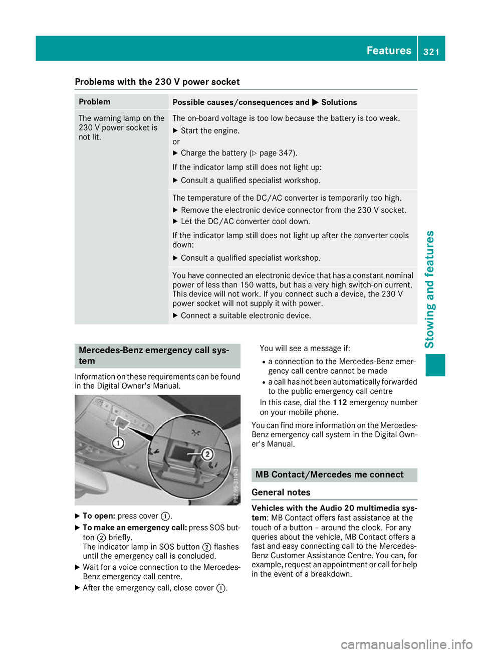
X Connect a suitable electronic device. Mercedes-Benz emergency call sys-
tem
Information on these requirements can be found in the Digital Owner's Manual. X
To open: press cover :.
X To make an emergency call: press SOS but-
ton ;briefly.
The indicator lamp in SOS button ;flashes
until the emergency call is concluded.
X Wait for a voice connection to the Mercedes-
Benz emergency call centre.
X After the emergency call, close cover :.You will see a message if:
R a connection to the Mercedes-Benz emer-
gency call centre cannot be made
R a call has not been automatically forwarded
to the public emergency call centre
In this case, dial the 112emergency number
on your mobile phone.
You can find more information on the Mercedes- Benz emergency call system in the Digital Own-
er's Manual. MB Contact/Mercedes me connect
General notes Vehicles with the Audio 20 multimedia sys-
tem: MB Contact offers fast assistance at the
touch of a button – around the clock. For any
queries about the vehicle, MB Contact offers a
fast and easy connecting call to the Mercedes-
Benz Customer Assistance Centre. You can, for
example, request an appointment or call for help in the event of a breakdown. Features
321Stowing and features Z
Page 325 of 389
Vehicles with the COMAND Online multime-
dia system: Mercedes me connect offers fast
assistance at the touch of a button – around the clock. For any queries about the vehicle,
Mercedes me connect offers a fast and easy
connecting call to the Mercedes-Benz CustomerAssistance Centre. You can, for example,
request an appointment or call for help in the
event of a breakdown.
The display of the multimedia system indicates
that a call is active. During the call, you can
change to the navigation menu by pressing the
Ø button on the multimedia system, for
example. Voice output is not available in this
case.
The Digital Owner's Manual contains further
information about:
R vehicles with the AUDIO 20 multimedia
system: MB Contact
R vehicles with the COMAND Online multi-
media system: Mercedes me connect
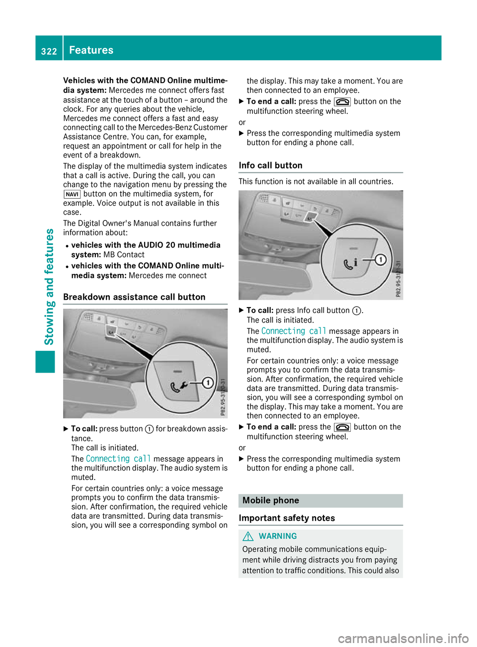
Breakdown assistance call button X
To call: press button :for breakdown assis-
tance.
The call is initiated.
The Connecting call
Connecting call message appears in
the multifunction display. The audio system is
muted.
For certain countries only: a voice message
prompts you to confirm the data transmis-
sion. After confirmation, the required vehicle
data are transmitted. During data transmis-
sion, you will see a corresponding symbol on the display. This may take a moment. You are
then connected to an employee.
X To end a call: press the~button on the
multifunction steering wheel.
or X Press the corresponding multimedia system
button for ending a phone call.
Info call button This function is not available in all countries.
X
To call: press Info call button :.
The call is initiated.
The Connecting call
Connecting call message appears in
the multifunction display. The audio system is muted.
For certain countries only: a voice message
prompts you to confirm the data transmis-
sion. After confirmation, the required vehicle
data are transmitted. During data transmis-
sion, you will see a corresponding symbol on
the display. This may take a moment. You are
then connected to an employee.
X To end a call: press the~button on the
multifunction steering wheel.
or
X Press the corresponding multimedia system
button for ending a phone call. Mobile phone
Important safety notes G
WARNING
Operating mobile communications equip-
ment while driving distracts you from paying
attention to traffic conditions. This could also 322
FeaturesStowing and features
Page 326 of 389
cause you to lose control of the vehicle. There
is a risk of an accident.
Use this device only when the vehicle is sta-
tionary.
You must observe the legal requirements for the country in which you are currently driving whenoperating mobile communications equipment in
the vehicle.
If it is permitted by law to operate communica-
tions equipment while the vehicle is in motion,
you may do so only if the traffic situation per-
mits. You may otherwise be distracted from the traffic conditions, cause an accident and injure
yourself and others.
Excessive levels of electromagnetic radiation
may cause damage to your health and to the
health of others. The use of an exterior aerial
takes into consideration the scientific discus-
sion surrounding the possible health risk posed
by electromagnetic fields.
Mercedes-Benz recommends the use of an
approved exterior aerial. This ensures:
R optimal mobile phone reception quality in the
vehicle
R that mutual interference between the vehicle
electronics and mobile phones is minimised
An exterior aerial has the following advantages:
R it conducts the electromagnetic fields gener-
ated by a wireless device to the exterior
R the field strength in the vehicle interior is
lower than in a vehicle that does not have an exterior aerial
Information on retrofitting two-way radios and
mobile phones (RF transmitters) (Y page 371).
General notes Depending on the vehicle equipment, there are
various mobile phone brackets that may be fit-
ted in your vehicle; in some cases, these are
country-specific.
More information on suitable mobile phones,
mobile phone brackets and on connecting Blue-
tooth ®
-capable mobile phones with the multi-
media system can be obtained:
R at a qualified specialist workshop
R on the internet at http://www.mercedes-
benz.com/connect The functions and services available when you
use the phone depend on your mobile phone
model and service provider.
Using a mobile phone To connect a mobile phone to the exterior aerial
and charge it, insert it into the mobile phone
bracket.
X Open the telephone compartment
(Y page 307).
X Place the mobile phone bracket into the pre-
installed fitting; see the separate installation
instructions for the mobile phone fitting.
X Insert the mobile phone into the mobile phone
bracket; see the separate installation instruc-
tions for the mobile phone fitting.
i The mobile phone can also be operated
without being in the bracket. However, the
charging function and aerial function are not
available.
In order to use Bluetooth ®
(SAP profile) on your
telephone module, you must first insert the tele-
phone module into the pre-installed fitting. This connects it to the exterior aerial. If you wish to
charge the mobile phone, you must connect it to
a USB port.
Further information on the telephone module
with Bluetooth ®
(SAP profile) can be found in the
Digital Owner's Manual.
Operating the mobile phone You can operate the phone using the
6and
~ buttons on the multifunction steering
wheel. You can operate other mobile phone
functions via the on-board computer
(Y page 238).
When you remove the key from the ignition lock, the mobile phone is disconnected from the vehi-cle. You can then no longer make calls using the
hands-free system.
If a call is active and you remove the key from
the ignition lock, the conversation is transferred
over to the mobile phone. It is then possible to
continue the conversation on the mobile phone. Features
323Stowing and features Z