2016 MERCEDES-BENZ GLC COUPE lock
[x] Cancel search: lockPage 226 of 389
To deactivate the switched power supply:
X Turn the key to position 0in the ignition lock
(Y page 144).
or
X Press the Start/Stop button once on vehicles
with KEYLESS-GO or the KEYLESS-GO start
function (Y page 144). Failure check for LEDs
If LED lamps are fitted in the trailer, a malfunc-
tion message may appear in the multifunction
display even if there is no fault. The reason for
the error message may be that the current has
fallen below the minimum of 50 mA.
To ensure reliable operation of the failure indi-
cator, each LED chain in the trailer lighting must
be guaranteed a minimum current of 50 mA. Trailer with 7-pin connector
General notes Trailer with 7-pin connector:
you can connect
to the 13-pin socket on the ball coupling using
an adapter or, if necessary, an adapter cable.
Both can be obtained at a qualified specialist
workshop. Fitting the adapter !
Make sure that there is sufficient cable play
so that the cable cannot become detached
when cornering.
! Remove the adapter cable before folding in
the ball coupling. You could otherwise dam-
age the rear bumper and the adapter cable. X
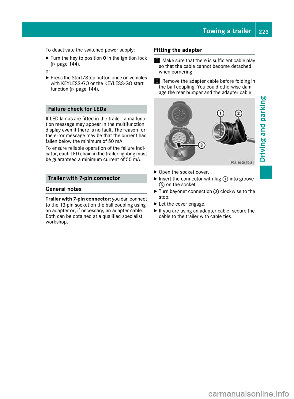
Open the socket cover.
X Insert the connector with lug :into groove
= on the socket.
X Turn bayonet connection ;clockwise to the
stop.
X Let the cover engage.
X If you are using an adapter cable, secure the
cable to the trailer with cable ties. Towing a trailer
223Driving and parking Z
Page 227 of 389
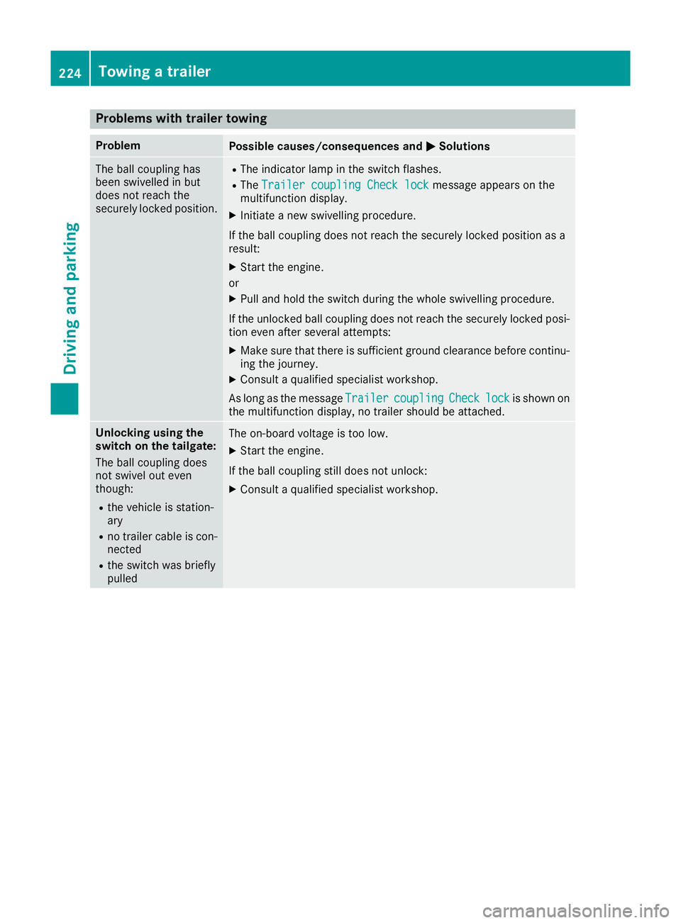
Problems with trailer towing
Problem
Possible causes/consequences and
M
MSolutions The ball coupling has
been swivelled in but
does not reach the
securely locked position. R
The indicator lamp in the switch flashes.
R The Trailer coupling Check lock Trailer coupling Check lock message appears on the
multifunction display.
X Initiate a new swivelling procedure.
If the ball coupling does not reach the securely locked position as a
result: X Start the engine.
or
X Pull and hold the switch during the whole swivelling procedure.
If the unlocked ball coupling does not reach the securely locked posi- tion even after several attempts:
X Make sure that there is sufficient ground clearance before continu-
ing the journey.
X Consult a qualified specialist workshop.
As long as the message Trailer Trailercoupling
coupling Check
Checklock
lockis shown on
the multifunction display, no trailer should be attached. Unlocking using the
switch on the tailgate:
The ball coupling does
not swivel out even
though:
R the vehicle is station-
ary
R no trailer cable is con-
nected
R the switch was briefly
pulled The on-board voltage is too low.
X Start the engine.
If the ball coupling still does not unlock:
X Consult a qualified specialist workshop. 224
Towing a trailerDriving and parking
Page 228 of 389
Problem
Possible causes/consequences and
M
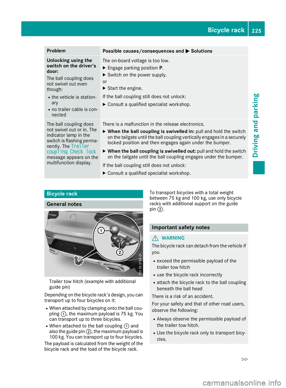
MSolutions Unlocking using the
switch on the driver's
door:
The ball coupling does
not swivel out even
though:
R the vehicle is station-
ary
R no trailer cable is con-
nected The on-board voltage is too low.
X Engage parking position P.
X Switch on the power supply.
or X Start the engine.
If the ball coupling still does not unlock: X Consult a qualified specialist workshop. The ball coupling does
not swivel out or in. The
indicator lamp in the
switch is flashing perma-
nently. The Trailer Trailer
coupling Check lock
coupling Check lock
message appears on the
multifunction display. There is a malfunction in the release electronics.
X When the ball coupling is swivelled in: pull and hold the switch
on the tailgate until the ball coupling vertically engages in a securely locked position and then engages again under the bumper.
X When the ball coupling is swivelled out: pull and hold the switch
on the tailgate until the ball coupling engages under the bumper.
If the ball coupling still does not unlock: X Consult a qualified specialist workshop. Bicycle rack
General notes
Trailer tow hitch (example with additional
guide pin)
Depending on the bicycle rack's design, you can transport up to four bicycles on it:
R When attached by clamping onto the ball cou-
pling :, the maximum payload is 75 kg. You
can transport up to three bicycles.
R When attached to the ball coupling :and
also the guide pin ;, the maximum payload is
100 kg. You can transport up to four bicycles.
The payload is calculated from the weight of the
bicycle rack and the load of the bicycle rack. To transport bicycles with a total weight
between 75 kg and 100 kg, use only bicycle
racks with additional support on the guide
pin
;. Important safety notes
G
WARNING
The bicycle rack can detach from the vehicle if
you
R exceed the permissible payload of the
trailer tow hitch
R use the bicycle rack incorrectly
R attach the bicycle rack to the ball coupling
beneath the ball head
There is a risk of an accident.
For your safety and that of other road users,
observe the following:
R Always observe the permissible payload of
the trailer tow hitch.
R Use the bicycle rack only to transport bicy-
cles. Bicycle rack
225Driving and parking
Z
Page 234 of 389
R
È SPEEDTRONIC (Y page 176)
R ¯ Cruise control (Y page 174)
R a DISTRONIC PLUS Steering Assist and
Stop&Go Pilot (Y page 184)
R _ Adaptive Highbeam Assist
(Y page 119)
R _ Adaptive Highbeam Assist Plus
(Y page 119)
R è ECO start/stop function (Y page 148)
R ë HOLD function (Y page 186)
R ð Maximum permissible speed exceeded
(for certain countries only) Head-up display
General notes The Head-up Display projects information from
the navigation system and the driver assistance
systems above the dashboard into the driver's
field of vision. This way, the Head-up Display
enables drivers to see information without hav-
ing to take their eyes off the road.
A requirement for the display of the content is
that the following functions are available in the
vehicle and are switched on:
R Cruise control
R SPEEDTRONIC
R DISTRONIC PLUS
R Traffic Sign Assist
R Navigation
Important safety notes The head-up display is only an aid and is not a
substitute for attentive driving.
Speed limits and overtaking restrictions are not
always correctly displayed. Traffic signs always
have priority over the Traffic Sign Assist display.
The visibility of the head-up display is influenced by the following conditions:
R the driver's seat position
R the positioning of the display image
R the general light conditions
R sunglasses with polarisation filters
R wet road surfaces
R blocking of sunlight by objects on the display
cover In the event of extreme sunlight, sections of the
display may fade. This can be reversed by
switching the head-up display off and on again.
i Vehicles with the head-up display are equip-
ped with a special windscreen. Should repairs
be necessary, have the windscreen replaced
at a qualified specialist workshop.
Displays and operation Switching the head-up display on/off
X
Press the :button.
When the head-up display is switched on, the display appears in the driver's field of vision.
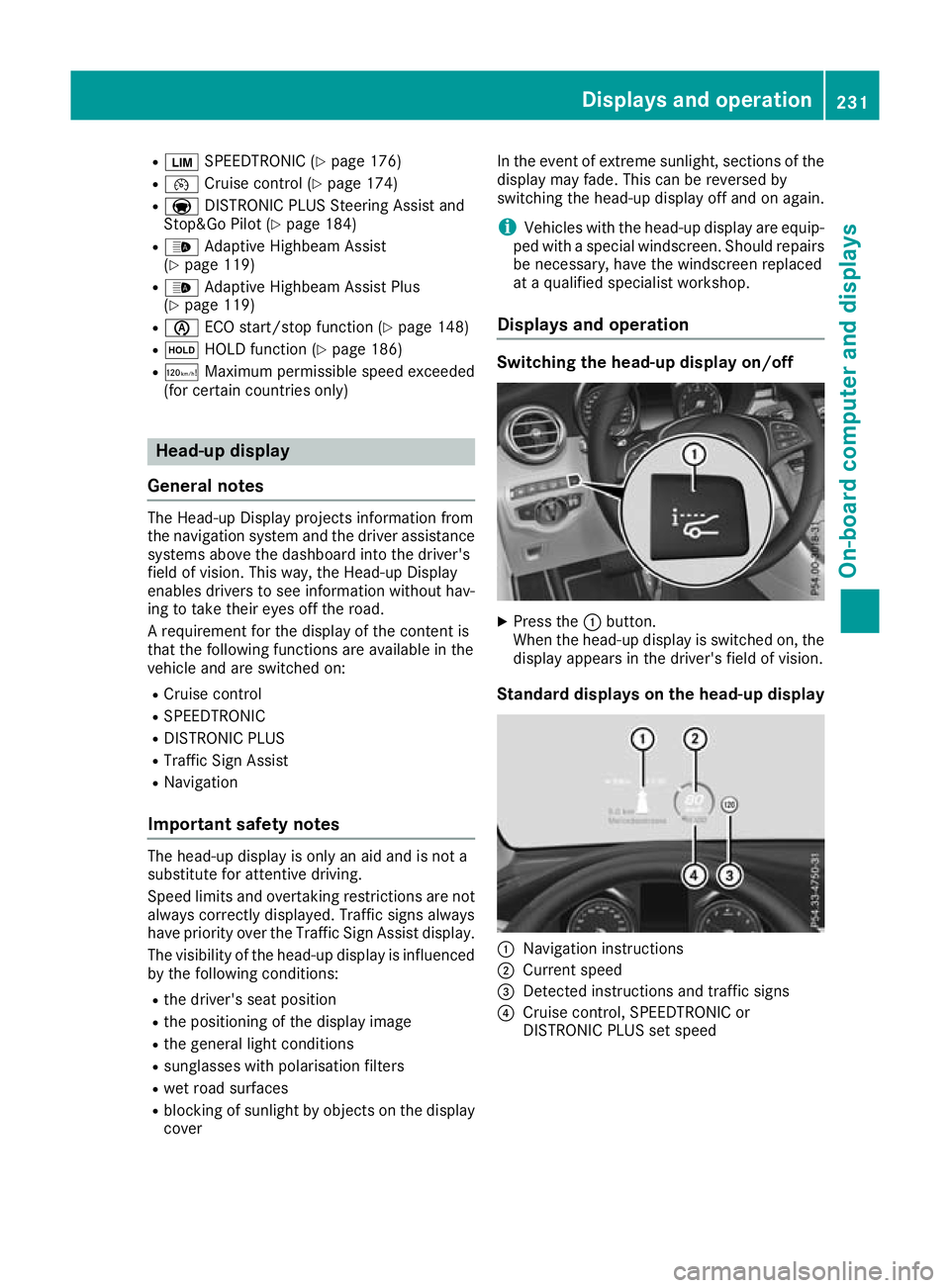
Standard displays on the head-up display :
Navigation instructions
; Current speed
= Detected instructions and traffic signs
? Cruise control, SPEEDTRONIC or
DISTRONIC PLUS set speed Displays and operation
231On-board computer and displays Z
Page 253 of 389
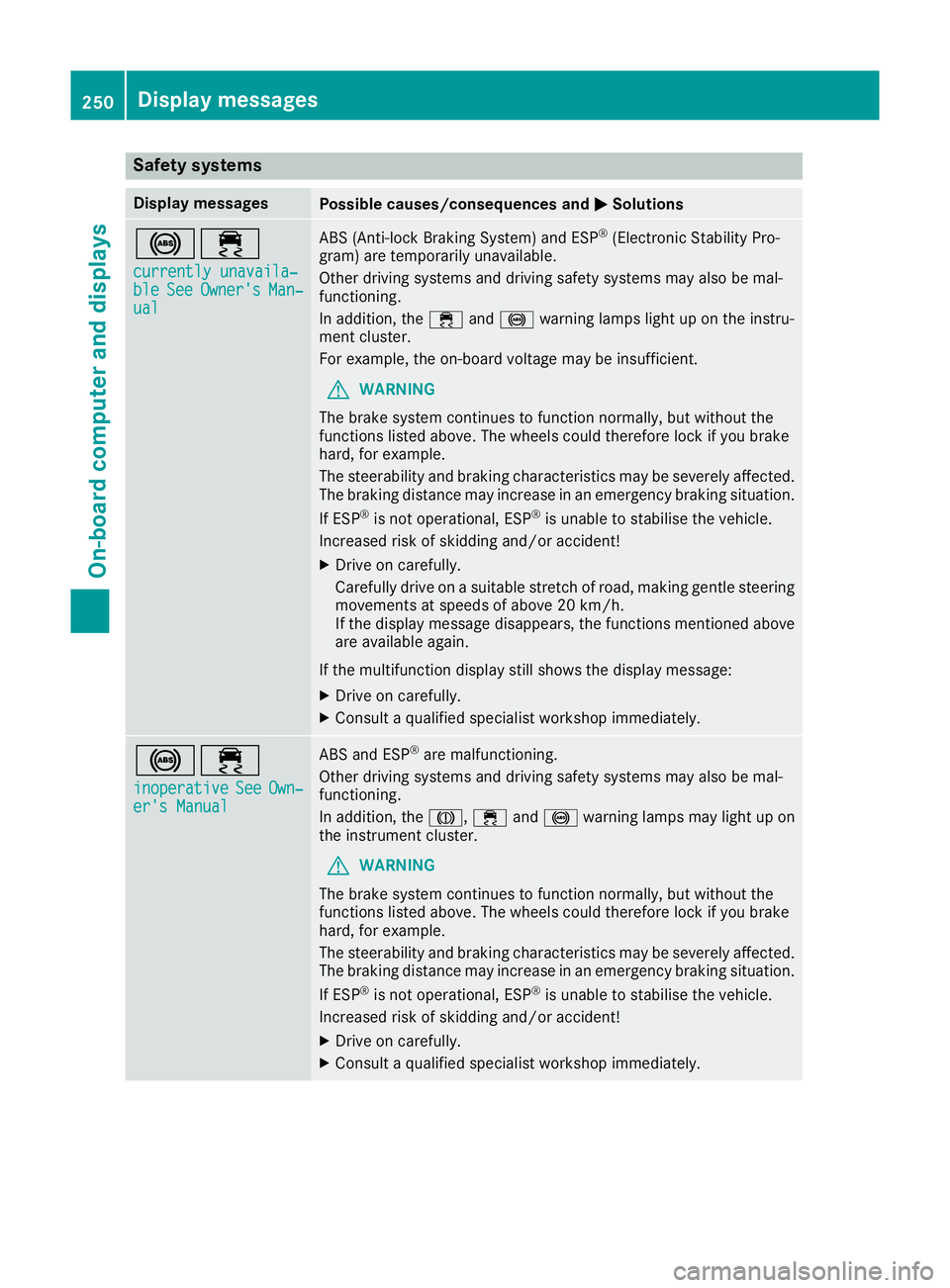
Safety systems
Display messages
Possible causes/consequences and
M
MSolutions !÷
currently unavaila‐
currently unavaila‐
ble ble See
SeeOwner's
Owner's Man‐
Man‐
ual
ual ABS (Anti-lock Braking System) and ESP
®
(Electronic Stability Pro-
gram) are temporarily unavailable.
Other driving systems and driving safety systems may also be mal-
functioning.
In addition, the ÷and! warning lamps light up on the instru-
ment cluster.
For example, the on-board voltage may be insufficient.
G WARNING
The brake system continues to function normally, but without the
functions listed above. The wheels could therefore lock if you brake
hard, for example.
The steerability and braking characteristics may be severely affected. The braking distance may increase in an emergency braking situation.
If ESP ®
is not operational, ESP ®
is unable to stabilise the vehicle.
Increased risk of skidding and/or accident!
X Drive on carefully.
Carefully drive on a suitable stretch of road, making gentle steering
movements at speeds of above 20 km/h.
If the display message disappears, the functions mentioned above
are available again.
If the multifunction display still shows the display message: X Drive on carefully.
X Consult a qualified specialist workshop immediately. !÷
inoperative inoperative See SeeOwn‐
Own‐
er's Manual
er's Manual ABS and ESP
®
are malfunctioning.
Other driving systems and driving safety systems may also be mal-
functioning.
In addition, the J,÷and! warning lamps may light up on
the instrument cluster.
G WARNING
The brake system continues to function normally, but without the
functions listed above. The wheels could therefore lock if you brake
hard, for example.
The steerability and braking characteristics may be severely affected. The braking distance may increase in an emergency braking situation.
If ESP ®
is not operational, ESP ®
is unable to stabilise the vehicle.
Increased risk of skidding and/or accident!
X Drive on carefully.
X Consult a qualified specialist workshop immediately. 250
Display messagesOn-board computer and displays
Page 254 of 389
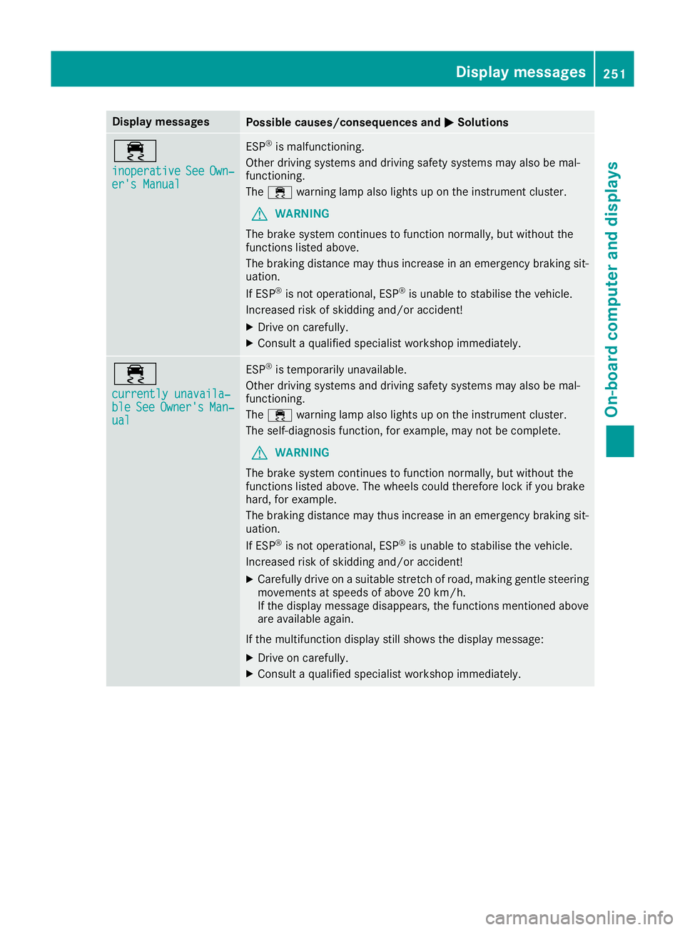
Display messages
Possible causes/consequences and
M
MSolutions ÷
inoperative inoperative
See
SeeOwn‐
Own‐
er's Manual
er's Manual ESP
®
is malfunctioning.
Other driving systems and driving safety systems may also be mal-
functioning.
The ÷ warning lamp also lights up on the instrument cluster.
G WARNING
The brake system continues to function normally, but without the
functions listed above.
The braking distance may thus increase in an emergency braking sit-
uation.
If ESP ®
is not operational, ESP ®
is unable to stabilise the vehicle.
Increased risk of skidding and/or accident!
X Drive on carefully.
X Consult a qualified specialist workshop immediately. ÷
currently unavaila‐ currently unavaila‐
ble ble
See
SeeOwner's
Owner's Man‐
Man‐
ual
ual ESP
®
is temporarily unavailable.
Other driving systems and driving safety systems may also be mal-
functioning.
The ÷ warning lamp also lights up on the instrument cluster.
The self-diagnosis function, for example, may not be complete.
G WARNING
The brake system continues to function normally, but without the
functions listed above. The wheels could therefore lock if you brake
hard, for example.
The braking distance may thus increase in an emergency braking sit-
uation.
If ESP ®
is not operational, ESP ®
is unable to stabilise the vehicle.
Increased risk of skidding and/or accident!
X Carefully drive on a suitable stretch of road, making gentle steering
movements at speeds of above 20 km/h.
If the display message disappears, the functions mentioned above
are available again.
If the multifunction display still shows the display message:
X Drive on carefully.
X Consult a qualified specialist workshop immediately. Display
messages
251On-board computer and displays Z
Page 255 of 389
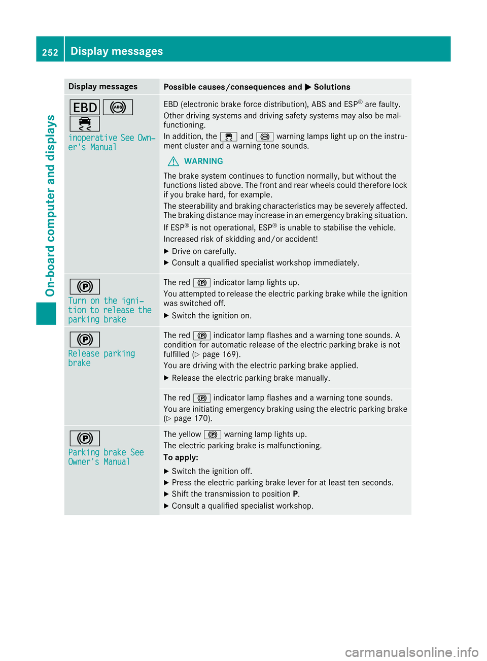
Display messages
Possible causes/consequences and
M
MSolutions T!
÷
inoperative inoperative See
SeeOwn‐
Own‐
er's Manual
er's Manual EBD (electronic brake force distribution), ABS and ESP
®
are faulty.
Other driving systems and driving safety systems may also be mal-
functioning.
In addition, the ÷and! warning lamps light up on the instru-
ment cluster and a warning tone sounds.
G WARNING
The brake system continues to function normally, but without the
functions listed above. The front and rear wheels could therefore lock
if you brake hard, for example.
The steerability and braking characteristics may be severely affected. The braking distance may increase in an emergency braking situation.
If ESP ®
is not operational, ESP ®
is unable to stabilise the vehicle.
Increased risk of skidding and/or accident!
X Drive on carefully.
X Consult a qualified specialist workshop immediately. !
Turn on the igni‐ Turn on the igni‐
tion tion
to
torelease
release the
the
parking brake
parking brake The red
!indicator lamp lights up.
You attempted to release the electric parking brake while the ignition
was switched off.
X Switch the ignition on. !
Release parking Release parking
brake brake The red
!indicator lamp flashes and a warning tone sounds. A
condition for automatic release of the electric parking brake is not
fulfilled (Y page 169).
You are driving with the electric parking brake applied.
X Release the electric parking brake manually. The red
!indicator lamp flashes and a warning tone sounds.
You are initiating emergency braking using the electric parking brake
(Y page 170). !
Parking brake See Parking brake See
Owner's Manual Owner's Manual The yellow
!warning lamp lights up.
The electric parking brake is malfunctioning.
To apply:
X Switch the ignition off.
X Press the electric parking brake lever for at least ten seconds.
X Shift the transmission to position P.
X Consult a qualified specialist workshop. 252
Display
messagesOn-board computer and displays
Page 266 of 389
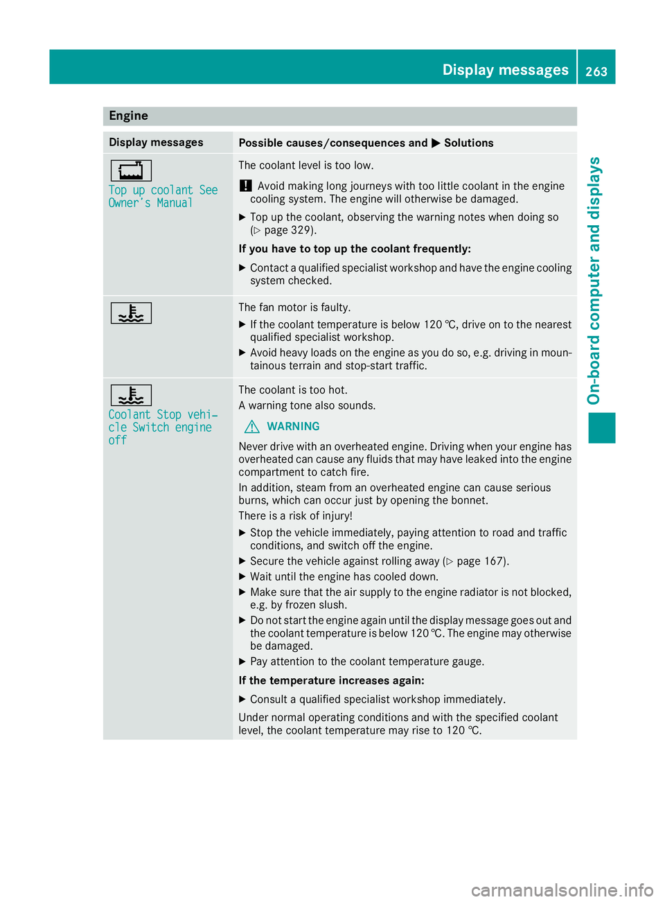
Engine
Display messages
Possible causes/consequences and
M
MSolutions +
Top up coolant See Top up coolant See
Owner’s Manual Owner’s Manual The coolant level is too low.
! Avoid making long journeys with too little coolant in the engine
cooling system. The engine will otherwise be damaged.
X Top up the coolant, observing the warning notes when doing so
(Y page 329).
If you have to top up the coolant frequently: X Contact a qualified specialist workshop and have the engine cooling
system checked. ? The fan motor is faulty.
X If the coolant temperature is below 120 †, drive on to the nearest
qualified specialist workshop.
X Avoid heavy loads on the engine as you do so, e.g. driving in moun-
tainous terrain and stop-start traffic. ?
Coolant Stop vehi‐ Coolant Stop vehi‐
cle Switch engine cle Switch engine
off off The coolant is too hot.
A warning tone also sounds.
G WARNING
Never drive with an overheated engine. Driving when your engine has
overheated can cause any fluids that may have leaked into the engine compartment to catch fire.
In addition, steam from an overheated engine can cause serious
burns, which can occur just by opening the bonnet.
There is a risk of injury!
X Stop the vehicle immediately, paying attention to road and traffic
conditions, and switch off the engine.
X Secure the vehicle against rolling away (Y page 167).
X Wait until the engine has cooled down.
X Make sure that the air supply to the engine radiator is not blocked,
e.g. by frozen slush.
X Do not start the engine again until the display message goes out and
the coolant temperature is below 120 †. The engine may otherwisebe damaged.
X Pay attention to the coolant temperature gauge.
If the temperature increases again:
X Consult a qualified specialist workshop immediately.
Under normal operating conditions and with the specified coolant
level, the coolant temperature may rise to 120 †. Display messages
263On-board computer and displays Z