2016 MERCEDES-BENZ G-CLASS SUV spare wheel
[x] Cancel search: spare wheelPage 12 of 261

Electromagnetic compatibility
Declaratio nofconformit y................ 22
Emergenc ycall9 99 or 112 .............. 179
Emergenc ykey
Unlocking the driver' sdoor.............. 62
Emergenc ykey element
Function/note s................................ 58
Genera lnotes .................................. 58
Inserting .......................................... 59
Locking vehicl e................................ 62
Removing ......................................... 58
Emergenc yrelease
Driver's doo r.................................... 62
Emergenc yunlocking
Vehicl e............................................. 62
Engine
Displa ymessage ............................ 146
ECO start/stop function .................. 97
Engine number ............................... 250
Jump-starting ................................. 227
Running irregularly ......................... 100
Starting problems .......................... 100
Starting the engine with the key ...... 96
Stopping ........................................ 114
Tow-starting (vehicle )..................... 232
Warning lamp (engine diagnos-
tics) ............................................... 162
Engine electronics
Note s............................................. 248
Problem (fault) ............................... 100
Engine oil
Additives ........................................ 253
Checking the oi llev el ..................... 213
Checking the oi llev el using the
dipstick .......................................... 213
Checking the oi llev el using the
on-board compute r........................ 213
Displa ymessage ............................ 147
Filling capacity ............................... 253
Genera lnotes ................................ 252
Note sabout oilg rade s................... 252
Note sono illevel/consumption .... 213
Topping up ..................................... 213
Entering an address .......................... 182
Entering the town .............................. 182
Environmental protection
Returning an end-of-life vehicl e....... 20 ESP
®
(Electroni cStability Pro-
gram)
Characteristics ................................ .54
Deactivating/activating ................... 54
Display message ............................ 142
Function/note s................................ 53
Genera lnotes .................................. 53
Important safety guideline s............. 54
Trailer stabilisation .......................... 55
Warning lamp ................................. 159
ETS/4ETS (Electroni cTraction Sys-
tem) ...................................................... 54
Exhaust
see Exhaus tpipe
Exhaus tpipe
Cleaning ......................................... 219
Exterior lighting
Cleaning ......................................... 219
see Lights F
Factor ysettings ................................ 173
Fault message
see Display messages
File formats ........................................ 178
Filler cap
see Fuel fille rflap
Fire extinguisher .............................. .222
First-aid kit ......................................... 222
Fitting awheel
Fitting awheel ............................... 245
Lowering the vehicle ..................... .246
Preparing the vehicle ..................... 243
Raising the vehicle ......................... 244
Removing awheel .......................... 245
Securing the vehicle against roll-
ing away ........................................ 244
Flat tyre
Changing awheel/fitting the
spare wheel ................................... 243
Preparing the vehicle ..................... 224
Foldin gthe seat backrest (rear)
forwards/back .................................. 201
Frequencies
Mobile phone ................................. 248
Two-way radio ................................ 248 Index
9
Page 18 of 261

with luggage compartment
enlargement .................................. 205
without luggage compartment
enlargement .................................. 204
SD function
Important safet ynotes .................. 177
Inserting amemory car d............... .177
Selecting ........................................ 177
SD memory card
Ejecting .......................................... 177
Inserting ........................................ 177
Seat
Correct driver's seat position .......... .67
Seat backrest
Folding back ..................................2 01
Seat belt
Centre rear-compartment sea t....... .34
Correct usage .................................. 33
Sea tbelts
Cleaning ........................................ .221
Fastening ......................................... 34
Important safety guidelines ............. 32
Introduction ..................................... 32
Releasing ......................................... 35
Warning lamp ................................. 155
Warning lamp (function) ................... 36
Seat heating
Malfunction indicator lamp .............. 71
Seats
Adjusting the hea drestraint ............ 69
Cleaning the cover ......................... 220
Important safety notes .................... 67
Overview .......................................... 67
Switching sea theating on/off ......... 70
Securing aload .................................. 202
Selector lever
Cleaning ......................................... 220
Service menu (on-board com-
puter) ................................................. .137
Service products
AdBlue ®
special additive s.............. 251
Brake fluid ..................................... 253
Coolant (engine) ............................ 253
Engine oi l....................................... 252
Fue l................................................ 250
Important safety notes .................. 250
Note s............................................. 250
Washe rfluid ................................... 254 Setting
Time............................................... 138
Setting the air distribution ................. 86
Setting the date ................................. 172
Setting the day design ......................172
Settin gthe night design ................... 172
Settin gthe time ................................. 172
Settin gthe waveband ....................... 176
Settings
Date ............................................... 138
Factory (on-board computer) ......... 141
Language ....................................... 138
On-board computer ....................... 137
Shift ranges ....................................... 105
Short journey s(diesel particle fil-
ter) ...................................................... 115
Side lamps
Switching on/off .............................. 75
Side windows
Important safety notes .................... 64
Opening/closing .............................. 64
Overview .......................................... 64
Sliding sunroof
Important safety information ........... 65
Opening/closing .............................. 65
Operating manually .......................... 65
Problem (malfunction) ..................... 66
Sno wchains ...................................... 237
Socket (12 V)
Front-passenger footwell .............. .209
General notes ................................ 209
Luggage compartment ................... 209
Rea rcompartment ......................... 209
Soun dsettings
Equaliser ........................................ 171
Loudness ....................................... 171
Spare fuses ........................................ 233
Spare wheel
Spare wheel bracket at the rear .... 223
Specialist workshop ............................ 23
Speedometer
Digita l............................................ 134
In the Instrument cluster ................. 26
Selecting adispla yunit .................. 137
Starting the engine
Important safety notes .................... 96 Index
15
Page 123 of 261

Observe the following notes:
R stop the vehicle before you drive off-road and,
if necessary, shift the transfer case to the
LOW RANGE off-road driving position
(Y page 124)
R engage the differential locks if necessary
(Y page 126)
i ABS,4
ETS, ESP ®
and BAS are deactivated
while the differential locks are engaged. This
allowst he front wheels to lock briefly, so that
they can dig into aloose surface. However,
please note that locked wheels skid and can
no longer steer.
R Make sure that items of luggage and loads are
stowed safely and are well secured
(Y page 203).
R To avoid damaging the vehicle, make sure
there is always sufficient ground clearance.
R Alwaysk eep the engine running and in gear
when driving on adownhill gradient.
R Alwaysk eep the engine running and in gear
when driving on aslope.
R Drive slowly and evenly, if necessary at walk-
ing pace.
R Ensure that the wheels are in contact with the
ground at all times.
R Drive with extreme care on unknown off-road
routes where visibility is poor. For safety rea- sons, get out of the vehicle first and survey
the off-road route.
R Check the depth of water before fording rivers
and streams.
R Watch out for obstacles.
R Alwaysk eep the doors, the rear door, the side
windows and the sliding sunroof closed while
the vehicle is in motion.
R Do not deviate from marked routes.
R Match your speed to the terrain. The rougher,
steeper or more ruts on the terrain, the slower your speed should be.
R Do not jump with the vehicle. This will inter-
rupt the vehicle's propulsion.
R Avoid high engine speeds. Drive at appropri-
ate engine speeds.
R Alwaysc heck the vehicle for damage after off-
road driving.
Do not use the HOLD function when driving off- road, on steep uphillord ownhill gradients or on
slippery or loose surfaces. The HOLD function
cannot hold the vehicle on such surfaces. You can obtain further information aboutr
etro-
fittin gspecial all-terrain tyres from aqualified
specialis tworkshop.
Checklist before off-roa ddriving X
Engine oil level: check the engine oil and top
it up if necessary.
When driving on steep gradients, the oil level must be sufficiently high to ensure acorrect
oil supply in th evehicle.
X Hav ethe AdBlue ®
level checked at aqualified
specialist workshop (Y page 111).
X Tyre-change tool kit: check that thejackis
working and mak esure that th ewheel
wrench, arobus ttow cable and afolding
spade are in th evehicle.
X Wheels and tyres: check thetyret read
dept hand tyr epressure.
X Chec kfor damage and remove any foreign
objects, e.g .small stones, fro mthewheels/
tyres.
X Replace any missing valv ecaps.
X Replace dented or damage dwheels .Also
check th espare wheel.
X Wheels: dented or ben twheels can lead to a
loss of tyr epressure and damage to th etyre
bead. Before driving off-road, check the
wheels and replac ethemifn ecessary.
Checklist after off-roa ddriving !
If you detect damage to the vehicl
eafter
driving off-road, have the vehicle checked
immediately at aqualified specialist work-
shop.
Driving over rough terrain places greater
demands on your vehicle than driving on normal
roads. After driving off-road, check the vehicle.
This allowsy ou to detect damage promptly and
reduce the risk of an accident to yourselfa nd
other road users.
X Shift the transfer case to the on-road position
HIGH RANGE (Ypage 124).
X Disengage the differential locks
(Y page 127).
X Cleant he headlamps and rear lights and
check for damage.
X Cleant he front and rear licence plates.
X Cleant he wheels and tyres with awater jet
and remove any foreign objects. 120
Drivingt
ipsDriving and parking
Page 226 of 261

Observe the legal requirements for each indi-
vidualc ountry. Veh
icle toolkit
General notes The vehicl
etool kit contains:
R vehicle tool kit with:
- fuse extractor
- pump lever for vehicle jack
- screwdriver
- Wheel wrench
R jack
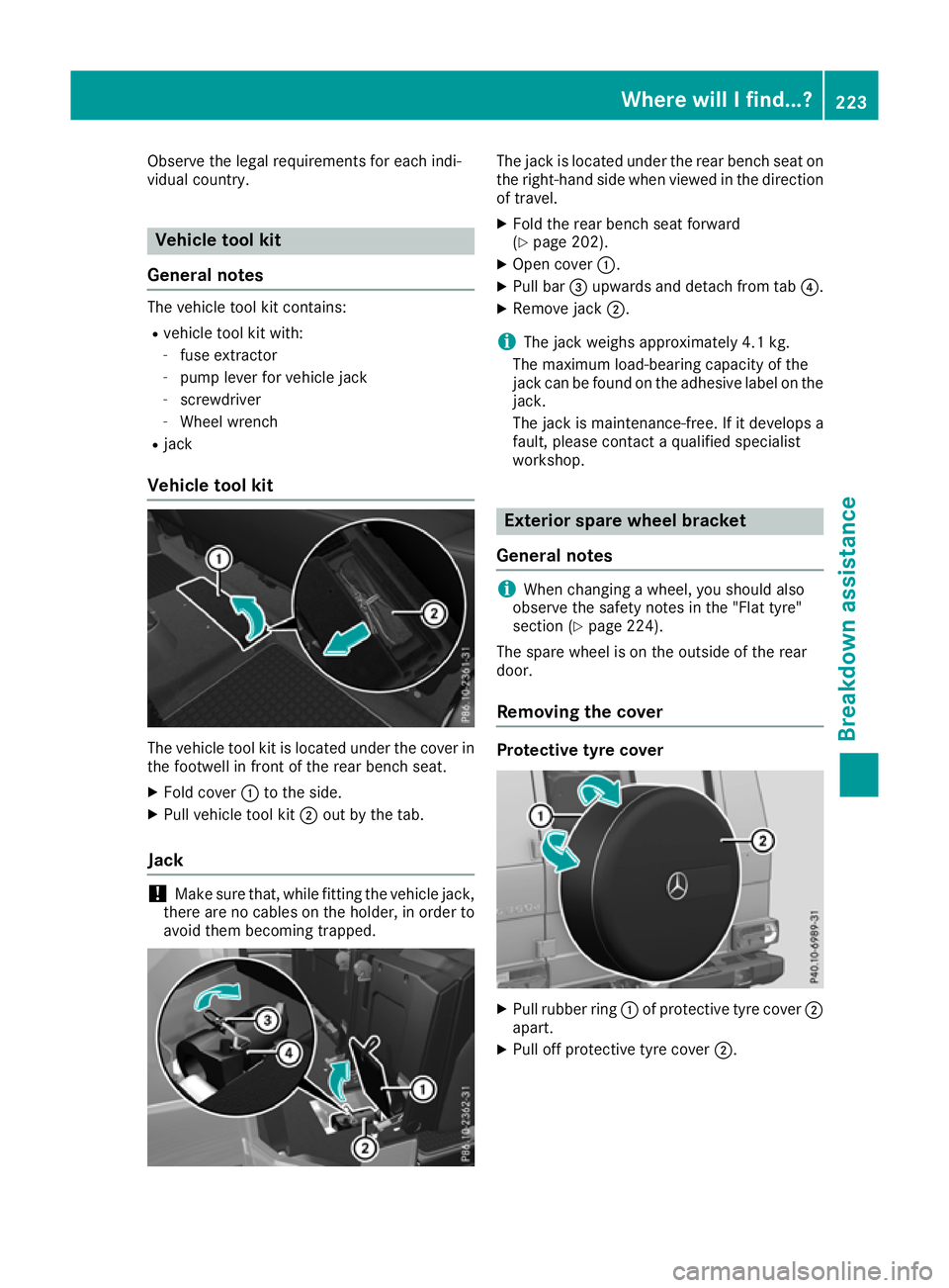
Vehicle tool kit The vehicle tool kit is located under the cover in
the footwell in front of the rear bench seat.
X Fold cover :to the side.
X Pull vehicle tool kit ;out by the tab.
Jack !
Make sure that, while fitting the vehicle jack,
there are no cables on the holder, in order to avoid them becoming trapped. The jack is located under the rear bench seat on
the right-hand side when viewed in the direction
of travel.
X Fold the rear bench seat forward
(Y page 202).
X Open cover :.
X Pull bar =upwards and detach from tab ?.
X Remove jack ;.
i The jack weighs approximately 4.1 kg.
The maximum load-bearing capacity of the
jack can be found on the adhesive label on the
jack.
The jack is maintenance-free. If it develops a
fault, please contact aqualified specialist
workshop. Exterior spare wheelb
racket
General notes i
When changin
gawheel, you should also
observe the safety notes in the "Flat tyre"
section (Y page 224).
The spare wheel is on the outside of the rear
door.
Removing the cover Protective tyrec
over X
Pull rubber ring :of protective tyre cover ;
apart.
X Pull off protective tyre cover ;. Wherew
illIf ind...?
223Breakdow nassistan ce
Page 227 of 261

Removin
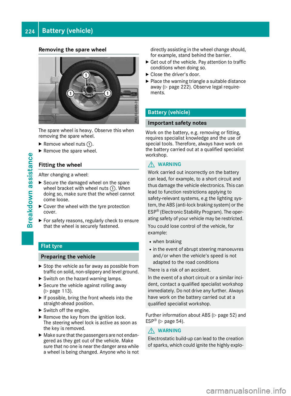
gthe spare wheel The spare wheel is heavy. Observ
ethis when
removing the spare wheel.
X Remove wheel nuts :.
X Remove the spare wheel.
Fitting the wheel After changing
awheel:
X Secure the damaged whee lonthe spare
whee lbracket with whee lnuts :.W hen
doing so, make sure tha tthe whee lcannot
come loose.
X Cover the whee lwitht he tyr eprotection
cover.
X For safety reasons ,regularly check to ensure
tha tthe whee lissecurel yfastened. Flat tyre
Preparing the vehicle
X Sto pthe vehicle as far away as possible from
traffic on solid, non-slippery and level ground.
X Switch on the hazard warning lamps.
X Secure the vehicle against rolling away
(Y page 113).
X If possible, bring the front wheels into the
straight-ahead position.
X Switch off the engine.
X Remove the key from the ignition lock.
The steering wheel lock is active as soon as
the key is removed.
X Make sure that the passengers are not endan-
gered as they get out of the vehicle. Make
sure that no one is near the danger area while
aw heel is being changed. Anyone who is not directly assisting in the wheel change should,
for example, stand behind the barrier.
X Get out of the vehicle. Pay attention to traffic
condition swhen doing so.
X Close the driver' sdoor.
X Place the warning triangle asuitable distance
away (Y page 222). Observe legal require-
ments. Batter
y(vehicle) Importan
tsafety notes
Wor kont hebattery, e.g. removing or fitting,
require sspecialist knowledge and th euse of
special tools. Therefore, always have wor kon
th eb attery carrie dout at aqualified specialist
workshop. G
WARNING
Work carried ou tincorrectly on the battery
can lead, for example, to ashort circui tand
thus damage the vehicl eelectronics. This can
leadtof unction restrictions applying to
safety-relevant systems ,e.g the lighting sys-
tem, the ABS (anti-lock braking system) or the
ESP ®
(Electronic Stability Program). The oper-
ating safety of yourv ehiclemay be restricted.
You coul dlose control of the vehicle, for
example:
R when braking
R in the event of abrupt steering manoeuvres
and/or when the vehicle's spee disnot
adapted to the road conditions
There is arisk of an accident.
In the event of ashort circui torasimilar inci-
dent, contact aqualified specialist workshop
immediately. Do not drive any further. Always have work on the battery carrie dout at a
qualified specialist workshop.
Further information about ABS (Y page52) and
ESP ®
(Y page5 4). G
WARNING
Electrostatic build-u pcan leadtot he creation
of sparks, which coul dignite the highly explo- 224
Battery (vehicle)Breakdown assistance
Page 235 of 261

In th
eevent of damage to th eengine,
transmission or electrical system X
Shift th etransfer cas etoneutral position
Neutral (Ypage 125).
X Shif tthe automatic transmissio ntoposition
N.
In the even tofdamage to the transfer
case Have the propeller shafts between the axles and
the transfe rcase removed.
In the event of damage to the front axle Have the propeller shaft between the rea
raxle
and the transfe rcase removed.
The nhavet he vehicle towe dawayw itht he front
axl eraised.
In the event of damage to the rear axle Have the propeller shaft between the front axle
and the transfe rcase removed.
The nhavet he vehicle towe dwitht he rea raxle
raised and wheel rollers unde rthe front axle. Tow-start
ing( em ergency engine
starting)
! Do not tow-start vehicles with automatic
transmission. Yo ucould otherwis edamage
the automatic transmission.
Yo uc an find informatio non"Jump-starting"
under (Y page 227). Fuses
Importan
tsafety notes G
WARNING
If yo umanipulate, bridge or replace afaulty
fuse with afuse of ahigher amperage ,the
electric cables coul dbeoverloaded. This may
result in afire. There is arisk of an accident
and injury.
Always replace faulty fuses with specified new fuses of the correct amperage. The fuses in your vehicle disconnect fault
ycir-
cuits. If afuse blows, all the components in the
circuit and their functions will fail.
Blown fuses must be replaced with fuses of the same rating, which you can recognise by the
colour and fuse rating. The fuse ratings are listed
in the fuse allocation chart (Y page 233).
If the newly inserted fuse also blows, have the
cause traced and rectified at aqualified special-
ist workshop, e.g. aMercedes-Benz Service
Centre.
! Only use fuses that have been approved for
Mercedes-Benz vehicles and which have the
correc tfuse rating for the system concerned.
Otherwise, components or systems could be
damaged.
! Make sure that no moisture can enter the
fuse box when the cover is open.
! When closing the cover, make sure that it is
lying correctly on the fuse box. Moisture seep-
ing in or dirt could otherwise impair the oper-
ation of the fuses. Bef
orer eplacing afuse
Observ ethe important safety notes
(Y page 232).
X Switch off the engine.
X Switch off al lelectrical consumers.
X Remove the key from the ignition lock.
All indicator lamps on the instrument cluster
must be off.
X Secure the vehicl eagain st rolling away
(Y page 113).
The fuses are locate dinvarious fus eboxes:
R Main fus eboxon the front-passenger side of
the dashboard
R Fus eboxin the front-passenger footwell
R Fus eboxin the transmission tunnel
R Fus eboxin the luggage compartment
The fus ealloc ation chart and the spare fuses are
in the fus eboxon the dashboard on the front-
passenger side (Y page 233).
The fus eextractor is in the vehicl etool kit
(Y page 223). 232
FusesBreakdo
wn assis tance
Page 239 of 261

Pay particular attention to damage such as:
R cuts in the tyres
R punctures
R tears in the tyres
R bulges on the tyres
R deformation or severe corrosion on the
wheels
Regularly check the tyre tread depth and the
condition of the tread across the whole width of
the tyre (Y page 236). In order to inspect the
inner side of the tyre surface, turn the steering
wheel to full lock.
All wheels must have avalve cap to protec tthe
valve against dirt and moisture. Do not fit any-
thing ontot he valve other than the standard
valve cap or avalve cap approved by Mercedes-
Benz for your vehicle. Do not fit any other valve caps or systems, e.g. tyre pressure monitors.
You should regularly check the pressure of all
your tyres including the spare wheel, particu-
larly prior to long trips. Adjust the tyre pressure as necessary (Y page 238).
The service life of atyre depends on various fac-
tors, including the following:
R driving style
R tyre pressure
R mileage Notes on th
etyre tread G
WARNING
Insuffic ient tyre tread willr educe tyre trac-
tion. The tyre is no longer abletod issipate
water .This means that on wet road surfaces,
the risk of aquaplaning increases, in particular where spee disnot adapted to suitt he driving
conditions. There is arisk of accident.
If the tyre pressure is too high or too low,t yres
may exhibi tdifferent levels of wearatd iffer-
ent locations on the tyre tread. Thus ,you
should regularl ycheck the tread depth and
the condition of the tread across the entire
width of all tyres.
Minimu mtyre tread depth for:
R summe rtyres: 3mm
R M+S tyres: 4mm For safety reasons, replace the tyre
sbefore
the legally prescribed limit for the minimum
tyre trea ddepth is reached. Select
ing, fitting and replacing tyres G
WARNING
Exceeding the state dtyre load-bearing capa-
city and the approved maximu mspee dcould
leadtot yre damage or the tyre bursting. There
is ar isk of accident.
Therefore, only use tyre types and sizes
approved for yourv ehiclemodel .Observe the
tyre loadr ating and spee drating required for
yourv ehicle.
Pay special attention to country-specific
requirements for tyre approval .These require-
ments may stipulate aspecific tyre type for your
vehicle. Furthermore ,the use of aspecific tyre
type in certain regions and area sofoperation
can be highly beneficial .You can find further
information regarding tyres at specialist tyre
retailers, at qualified specialist workshops or at
any Mercedes-Benz Service Centre.
R Use only tyres and wheels of the same type
and make.
R Fit only tyres of the correct size onto the
wheels.
R Runinn ew tyres at moderate speeds for the
first 100 km. They reach their full perform-
ance only after this distance.
R Do not drive with tyres that have too little
tread depth. This significantly reduces trac-
tion on wet road s(aquaplaning).
R Replace the tyres after six years at the latest,
regardless of wear. This alsoa ppliestothe
spar ewheel. Winter operation
General notes
Have yourv ehicle winterproofed at aqualified
specialist workshop at the onset of winter.
Observe the notes in the "Changing awheel"
section (Y page 243). 236
Winter operationWheels and tyres
Page 243 of 261

For further information on displaying this mes-
sage, refe rtothe "Checking the tyre pressure
electronically" section (Y page 240).
Important safety notes It is the driver's responsibility to set the tyre
pressure to the recommended cold tyre pres-
sure suitable for the operating situation
(Y page 238). Note that the correc ttyre pres-
sure for the current operating situation must
first be learnt by the tyre pressure monitor. If a
substantial loss of pressure occurs, the warning threshold for the warning message is aligned to
the learnt reference values. Restart the tyre
pressure monitor after adjusting to the cold tyre pressure (Y page 241). The current pressures
are saved as new reference values. This ensures that awarning message appears only if the tyre
pressure drops significantly.
The tyre pressure monitor does not warn you of
an incorrectly set tyre pressure. Observe the
notes on the recommended tyre pressure
(Y page 238).
The tyre pressure monitor is not abletow arn
you of asudden loss of pressure, e.g. if the tyre
is penetrated by aforeign object. In this event,
bring the vehicle to ahalt by braking carefully.
Avoid abrupt steering manoeuvres.
The tyre pressure monitor has ayellow h
warning lamp on the instrument cluster for indi-
cating apressure loss or malfunction. Depend-
ing on how the warning lamp flashe sorlights up,
at yre pressure that is too low or amalfunction in
the tyre pressure monitor is indicated:
R if the h warning lamp is lit continuously,
the tyre pressure on one or more tyres is sig-
nificantly too low. The tyre pressure monitor
is not malfunctioning.
R if the h warning lamp flashe sfor around a
minute and then remains lit constantly, the
tyre pressure monitor is malfunctioning.
In addition to the hwarning lamp,am essage
appears in the multifunction display. Observe
the information on display messages
(Y page 150).
It may take up to ten minutes for amalfunction
of the tyre pressure monitor to be indicated .A
malfunction willbei ndicated by thehtyre
pressure warning lamp flashing for approx-
imatel yone minute and then remaining lit. When
the faulth as been rectified, the htyre pres-
sure warning lamp goes out after driving for a
few minutes. The tyre pressure values indicated by the on-
board computer may differ from those meas-
ured at
afilling station using apressure gauge.
The tyre pressures shown by the on-board com-
puter refer to those measured at sea level. At
high altitudes, the tyre pressure values indica-
ted by apressure gauge are higher than those
shown by the on-board computer. In this case,
do not reduce the tyre pressures.
The operation of the tyre pressure monitor can
be affected by interferenc efrom radio transmit-
ting equipment (e.g. cordless headphones, two- way radios) that may be being operated in or
near the vehicle.
Checking the tyrep ressureelectroni-
cally X
Make sure that the key is in position 2in the
ignition lock.
X Press the =or; button on the steering
wheel to select the Serv.
Serv. menu.
X Press the 9or: button to select
Tyre pressure
Tyre pressure.
X Press the abutton.
The multifunction display shows the current
tyre pressure of each wheel.
If the vehicle has been parked for over
20 minutes, the Tyre pressures will be Tyre pressures will be
displayed
displayed after a
after afew
fewminutes
minutes of
ofdriv‐
driv‐
ing
ing message appears.
After ateach-in period, the tyre pressure moni-
tor automaticallyd etects new wheels or new
sensors. As long as aclear allocation of the tyre
pressure valuestot he individual wheels is not
possible,t heTyre
Tyre pressure
pressure monitor
monitoractive
active
displaym essage is shown instead of the tyre
pressure display. The tyre pressures are already being monitored.
If as pare wheel is fitted, the system may con-
tinue to show the tyre pressure of the wheel that has been removed for afew minutes. Please
note that in this case, the value displayed for the
replaced wheel does not indicate the current
tyre pressure of the spare wheel.
Warning messages of the tyre pressure monitor If the tyre pressure monitor detects
apressure
loss in one or more tyres, awarning messag eis
shown on the multifunction display. The yellow
h tyre pressure warning lamp then lights up. 240
Tyre pressureWheels and tyres