2016 MERCEDES-BENZ G-Class towing
[x] Cancel search: towingPage 171 of 302
Trailer with 7-pin connector
General notes
You can make a connection to the 13-pin socket
on the ball coupling using an adapter or, if nec-
essary, an adapter cable. Both can be obtained
in a qualified specialist workshop.
Installing the adapter
!Make sure that there is enough slack in the
cable for cornering so that the cable cannot
become detached.
XOpen the socket cover.
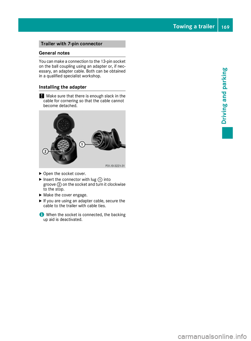
XInsert the connector with lug :into
groove ;on the socket and turn it clockwise
to the stop.
XMake the cover engage.
XIf you are using an adapter cable, secure the
cable to the trailer with cable ties.
iWhen the socket is connected, the backing
up aid is deactivated.
Towing a trailer169
Driving an d parking
Z
Page 229 of 302
If a connection can be made, theCall Con‐nectedmessage appears in the multifunction
display.
If a mobile phone network is available and there
is sufficient GPS reception, the mbrace system
transmits data to the Response Center, for
example:
Rcurrent location of the vehicle
Rvehicle identification number
Rvehicle model
Rvehicle color
iThe COMAND display shows that an mbrace
call is active. You can change to the naviga-
tion menu by pressing the NAVI button on
COMAND during the call. Voice output is not
available.
A voice connection is established between the
Mercedes-Benz Roadside Assistance Represen- tative and the vehicle occupants.
The Mercedes-Benz Roadside Assistance Rep-
resentative either sends a qualified Mercedes-
Benz technician or makes arrangements for
your vehicle to be transported to the nearest
authorized Mercedes-Benz Center. You may be
charged for services such as repair work and/or
towing. Further details are available in your
mbrace manual.
XDescribe the type of assistance needed.
iIf the indicator lamp in Roadside Assistance
button :is flashing continuously and no
voice connection with the Response center
has been established, then the mbrace sys-
tem has not been able to initiate a Roadside
Assistance call (e.g. the relevant mobile
phone network is not available). The Call
Failedmessage appears in the multifunction
display.
XTo end a call: press the~button on the
multifunction steering wheel.
or
XPress the corresponding COMAND button to
end a phone call.
iSign and drive services1: you are not
charged for services such as jump-starting,
providing a few gallons of fuel for a fuel tank
that has been run dry or changing a faulty tire
with the vehicle's own spare wheel.
MB Info call button
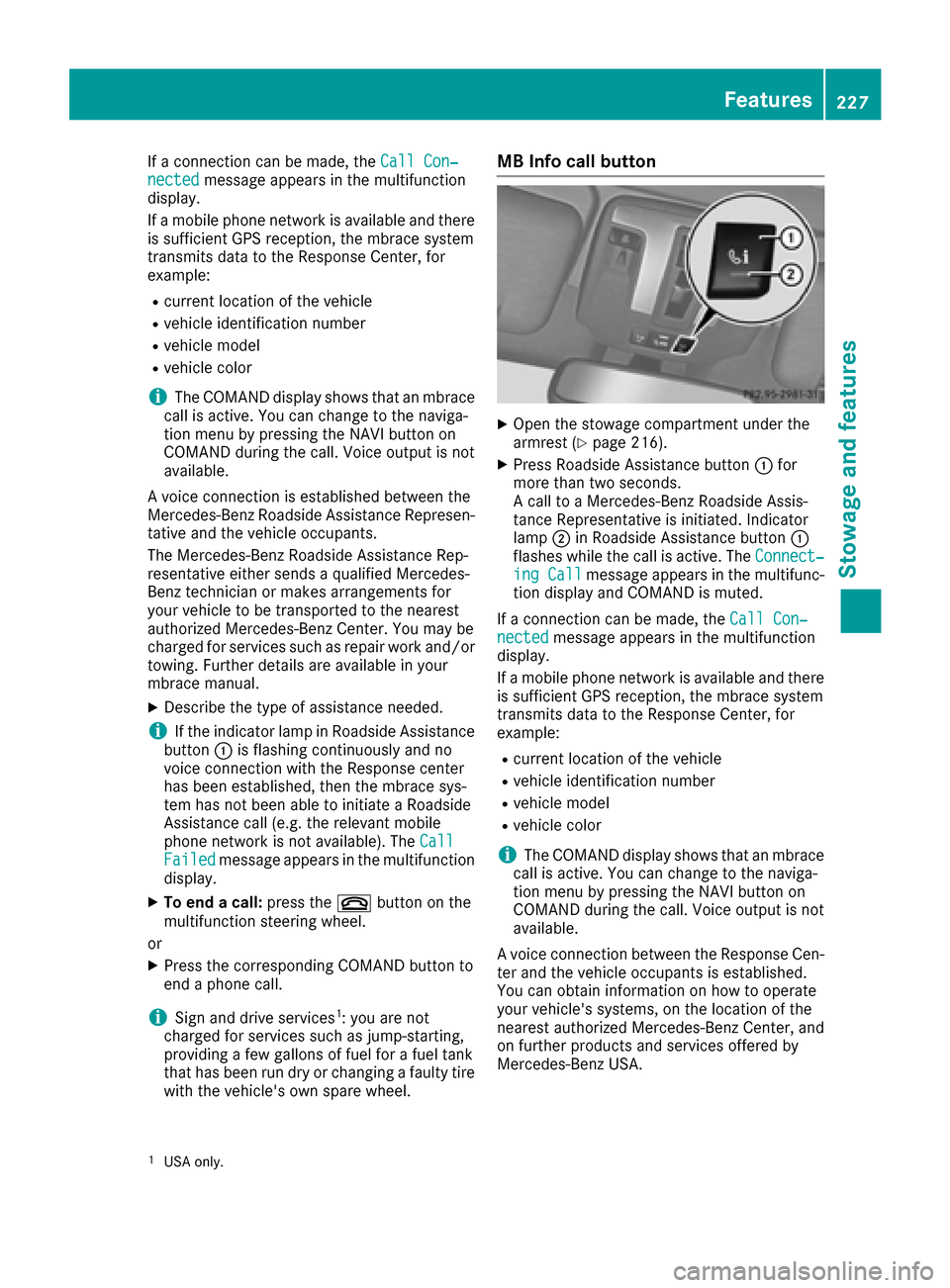
XOpen the stowage compartment under the
armrest (Ypage 216).
XPress Roadside Assistance button :for
more than two seconds.
A call to a Mercedes-Benz Roadside Assis-
tance Representative is initiated. Indicator
lamp ;in Roadside Assistance button :
flashes while the call is active. The Connect‐
ing Callmessage appears in the multifunc-
tion display and COMAND is muted.
If a connection can be made, the Call Con‐
nectedmessage appears in the multifunction
display.
If a mobile phone network is available and there
is sufficient GPS reception, the mbrace system
transmits data to the Response Center, for
example:
Rcurrent location of the vehicle
Rvehicle identification number
Rvehicle model
Rvehicle color
iThe COMAND display shows that an mbrace
call is active. You can change to the naviga-
tion menu by pressing the NAVI button on
COMAND during the call. Voice output is not
available.
A voice connection between the Response Cen- ter and the vehicle occupants is established.
You can obtain information on how to operate
your vehicle's systems, on the location of the
nearest authorized Mercedes-Benz Center, and
on further products and services offered by
Mercedes-Benz USA.
1USA only.
Features227
Stowage and features
Z
Page 258 of 302

XLift up cover:of positive terminal ;in the direction of the arrow.
XConnect positive terminal ;on your vehicle to positive terminal ?of donor battery Busing the
jumper cable. beginning with your own battery.
XStart the engine of the donor vehicle and run it at idling speed.
XConnect negative terminal Aof donor battery Bto ground point =of your vehicle using the
jumper cable, connecting the jumper cable to donor battery Bfirst.
XStart the engine.
XFirst, remove the jumper cables from ground point =and negative terminal A, then from pos-
itive clamp ;and positive terminal ?. Each time beginning with your vehicle's battery.
XHave the battery checked at a qualified specialist workshop.
iJump-starting is not considered to be a normal operating condition.
iJumper cables and further information regarding jump-starting can be obtained at any qualified
specialist workshop.
Towing and tow-starting
Important safety notes
GWARNING
Functions relevant to safety are restricted or
no longer available if:
Rthe engine is not running.
Rthe brake system or the power steering is
malfunctioning.
Rthere is a malfunction in the voltage supply or the vehicle's electrical system.
If your vehicle is being towed, much more
force may be necessary to steer or brake.
There is a risk of an accident.
In such cases, use a tow bar. Before towing,
make sure that the steering moves freely.
GWARNING
When towing or tow-starting another vehicle
and its weight is greater than the permissible
gross weight of your vehicle, the:
Rthe towing eye could detach itself
Rthe vehicle/trailer combination could roll-
over.
There is a risk of an accident.
When towing or tow-starting another vehicle,
its weight should not be greater than the per- missible gross weight of your vehicle.
!If DISTRONIC PLUS or the HOLD function is
activated, the vehicle brakes automatically in
certain situations. To prevent damage to the
vehicle, deactivate DISTRONIC PLUS and the
HOLD function in the following or other simi-
lar situations:
Rwhen towing the vehicle
Rin the car wash
!The vehicle can be towed a maximum of
30 miles (50km). The towing speed of 30 mph
(50 km/h) must not be exceeded.
If the vehicle has to be towed more than
30 miles (50km), the entire vehicle must be
raised and transported.
!Only secure the tow cable or tow bar to the
towing eyes. You could otherwise damage the
vehicle.
!Do not tow with sling-type equipment. This
could damage the vehicle.
!Do not use the towing eyes for recovery pur-
poses as this could damage the vehicle. If in
doubt, recover the vehicle with a crane.
!When towing, pull away slowly and
smoothly. If the tractive power is too high, the
vehicles could be damaged.
!Your vehicles is equipped with an automatic
transmission. Therefore, you must not have
the vehicle tow-started. The transmission
may otherwise be damaged.
iDetails on the permissible gross vehicle
weight of your vehicle can be found on the
vehicle identification plate (
Ypage 288).
256Towing and tow-starting
Breakdown assistance
Page 259 of 302
It is better to have the vehicle transported than
to have it towed away.
If the transfer case can be shifted into neutralN,
you can tow the vehicle.
If the transfer case cannot be shifted into neu-
tral N, you can tow the vehicle with one axle
raised. Please bear the following in mind:
Rremove the propeller shaft between the trans-
fer case and the rolling axle.
Rturn the SmartKey to position 1in the ignition
lock (Ypage 112).
The battery must be connected and charged.
Otherwise, you:
Rcannot turn the SmartKey to position 2in the
ignition lock (Ypage 112).
Rcannot shift the automatic transmission to
position N.
iDisarm the automatic locking feature before
the vehicle is towed (Ypage 66). You could
otherwise be locked out when pushing or tow-
ing the vehicle.
Towing eyes
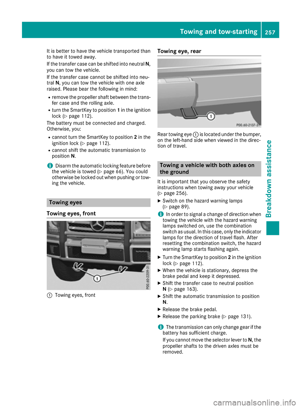
Towing eyes, front
:Towing eyes, front
Towing eye, rear
Rear towing eye :is located under the bumper,
on the left-hand side when viewed in the direc-
tion of travel.
Towing a vehicle with both axles on
the ground
It is important that you observe the safety
instructions when towing away your vehicle
(
Ypage 256).
XSwitch on the hazard warning lamps
(Ypage 89).
iIn order to signal a change of direction when
towing the vehicle with the hazard warning
lamps switched on, use the combination
switch as usual. In this case, only the indicator
lamps for the direction of travel flash. After
resetting the combination switch, the hazard
warning lamp starts flashing again.
XTurn the SmartKey to position 2in the ignition
lock (Ypage 112).
XWhen the vehicle is stationary, depress the
brake pedal and keep it depressed.
XShift the transfer case to neutral position
N (Ypage 163).
XShift the automatic transmission to position
N.
XRelease the brake pedal.
XRelease the parking brake (Ypage 131).
iThe transmission can only change gear if the
battery has sufficient charge.
If you cannot move the selector lever to N, the
propeller shafts to the driven axles must be
removed.
Towing and tow-starting257
Breakdown assistance
Z
Page 260 of 302
Transporting the vehicle
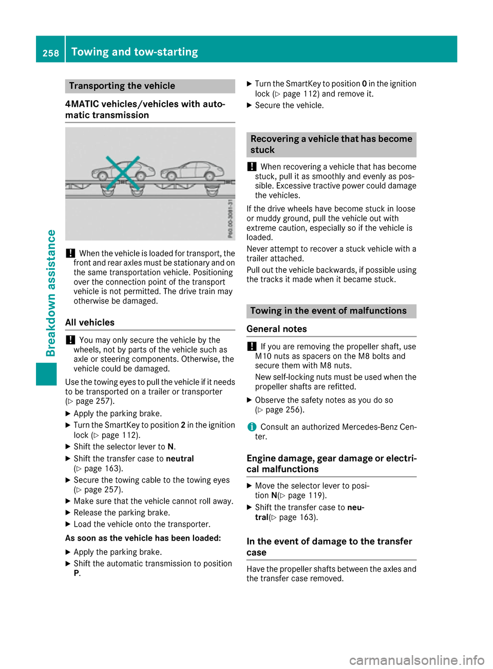
4MATIC vehicles/vehicles with auto-
matic transmission
!When the vehicle is loaded for transport, the
front and rear axles must be stationary and on the same transportation vehicle. Positioning
over the connection point of the transport
vehicle is not permitted. The drive train may
otherwise be damaged.
All vehicles
!You may only secure the vehicle by the
wheels, not by parts of the vehicle such as
axle or steering components. Otherwise, the
vehicle could be damaged.
Use the towing eyes to pull the vehicle if it needs
to be transported on a trailer or transporter
(
Ypage 257).
XApply the parking brake.
XTurn the SmartKey to position 2in the ignition
lock (Ypage 112).
XShift the selector lever to N.
XShift the transfer case toneutral
(Ypage 163).
XSecure the towing cable to the towing eyes
(Ypage 257).
XMake sure that the vehicle cannot roll away.
XRelease the parking brake.
XLoad the vehicle onto the transporter.
As soon as the vehicle has been loaded:
XApply the parking brake.
XShift the automatic transmission to position
P .
XTurn the SmartKey to position 0in the ignition
lock (Ypage 112) and remove it.
XSecure the vehicle.
Recovering a vehicle that has become
stuck
!
When recovering a vehicle that has become
stuck, pull it as smoothly and evenly as pos-
sible. Excessive tractive power could damage
the vehicles.
If the drive wheels have become stuck in loose
or muddy ground, pull the vehicle out with
extreme caution, especially so if the vehicle is
loaded.
Never attempt to recover a stuck vehicle with a
trailer attached.
Pull out the vehicle backwards, if possible using the tracks it made when it became stuck.
Towing in the event of malfunctions
General notes
!If you are removing the propeller shaft, use
M10 nuts as spacers on the M8 bolts and
secure them with M8 nuts.
New self-locking nuts must be used when the
propeller shafts are refitted.
XObserve the safety notes as you do so
(Ypage 256).
iConsult an authorized Mercedes-Benz Cen-
ter.
Engine damage, gear damage or electri-
cal malfunctions
XMove the selector lever to posi-
tion N(Ypage 119).
XShift the transfer case to neu-
tral (Ypage 163).
In the event of damage to the transfer
case
Have the propeller shafts between the axles and
the transfer case removed.
258Towing and tow-starting
Breakdown assistance
Page 274 of 302
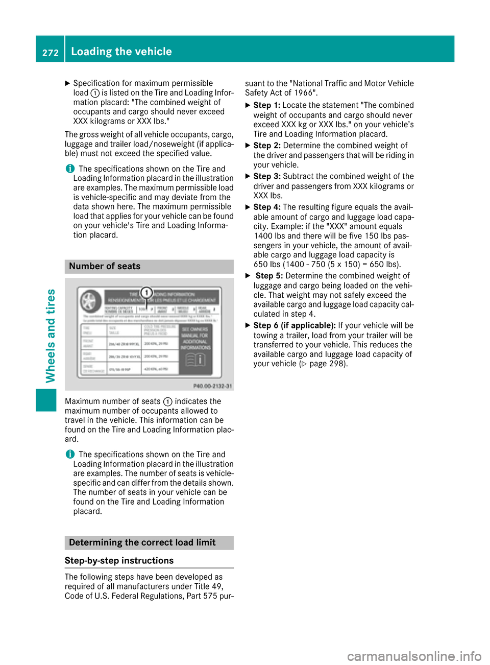
XSpecification for maximum permissible
load:is listed on the Tire and Loading Infor-
mation placard: "The combined weight of
occupants and cargo should never exceed
XXX kilograms or XXX lbs."
The gross weight of all vehicle occupants, cargo,
luggage and trailer load/noseweight (if applica-
ble) must not exceed the specified value.
iThe specifications shown on the Tire and
Loading Information placard in the illustration are examples. The maximum permissible load
is vehicle-specific and may deviate from the
data shown here. The maximum permissible
load that applies for your vehicle can be found
on your vehicle's Tire and Loading Informa-
tion placard.
Number of seats
Maximum number of seats :indicates the
maximum number of occupants allowed to
travel in the vehicle. This information can be
found on the Tire and Loading Information plac-
ard.
iThe specifications shown on the Tire and
Loading Information placard in the illustration
are examples. The number of seats is vehicle-
specific and can differ from the details shown.
The number of seats in your vehicle can be
found on the Tire and Loading Information
placard.
Determining the correct load limit
Step-by-step instructions
The following steps have been developed as
required of all manufacturers under Title 49,
Code of U.S. Federal Regulations, Part 575 pur- suant to the "National Traffic and Motor Vehicle
Safety Act of 1966".
XStep 1: Locate the statement "The combined
weight of occupants and cargo should never
exceed XXX kg or XXX lbs." on your vehicle’s
Tire and Loading Information placard.
XStep 2: Determine the combined weight of
the driver and passengers that will be riding in your vehicle.
XStep 3: Subtract the combined weight of the
driver and passengers from XXX kilograms or
XXX lbs.
XStep 4: The resulting figure equals the avail-
able amount of cargo and luggage load capa-
city. Example: if the "XXX" amount equals
1400 lbs and there will be five 150 lbs pas-
sengers in your vehicle, the amount of avail-
able cargo and luggage load capacity is
650 lbs (1400 - 750 (5 x 150) = 650 lbs).
XStep 5: Determine the combined weight of
luggage and cargo being loaded on the vehi-
cle. That weight may not safely exceed the
available cargo and luggage load capacity cal- culated in step 4.
XStep 6 (if applicable): If your vehicle will be
towing a trailer, load from your trailer will be
transferred to your vehicle. This reduces the
available cargo and luggage load capacity of
your vehicle (
Ypage 298).
272Loading the vehicle
Wheels and tires
Page 275 of 302
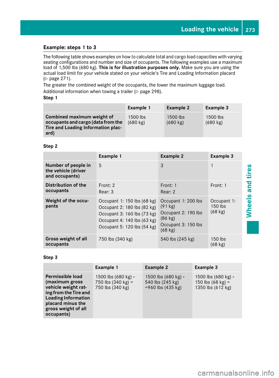
Example: steps 1 to 3
The following table shows examples on how to calculate total and cargo load capacities with varying
seating configurations and number and size of occupants. The following examples use a maximum
load of 1,500 lbs (680 kg). This is for illustration purposes only. Make sure you are using the
actual load limit for your vehicle stated on your vehicle's Tire and Loading Information placard
(
Ypage 271).
The greater the combined weight of the occupants, the lower the maximum luggage load.
Additional information when towing a trailer (
Ypage 298).
Step 1
Example 1Example 2Example 3
Combined maximum weight of
occupants and cargo (data from the
Tire and Loading Information plac-
ard)1500 lbs
(680 kg)1500 lbs
(680 kg)1500 lbs
(680 kg)
Step 2
Example 1Example 2Example 3
Number of people in
the vehicle (driver
and occupants)531
Distribution of the
occupantsFront: 2
Rear: 3Front: 1
Rear: 2Front: 1
Weight of the occu-
pantsOccupant 1: 150 lbs (68 kg)
Occupant 2: 180 lbs (82 kg)
Occupant 3: 160 lbs (73 kg)
Occupant 4: 140 lbs (63 kg)
Occupant 5: 120 lbs (54 kg)Occupant 1: 200 lbs
(91 kg)
Occupant 2: 190 lbs
(86 kg)
Occupant 3: 150 lbs
(68 kg)Occupant 1:
150 lbs
(68 kg)
Gross weight of all
occupants750 lbs (340 kg)540 lbs (245 kg)150 lbs
(68 kg)
Step 3
Example 1Example 2Example 3
Permissible load
(maximum gross
vehicle weight rat-
ing from the Tire and
Loading Information
placard minus the
gross weight of all
occupants)1500 lbs (680 kg) Ò
750 lbs (340 kg) =
750 lbs (340 kg)1500 lbs (680 kg) Ò
540 lbs (245 kg)
=960 lbs (435 kg)1500 lbs (680 kg) Ò
150 lbs (68 kg) =
1350 lbs (612 kg)
Loading the vehicle273
Wheels and tires
Z
Page 294 of 302
The vehicle will use more fuel than usual in the
following situations:
Rat very low outside temperatures
Rin city traffic
Ron short journeys
Rin mountainous terrain
Rwhen towing a trailer
Engine oil
General notes
!Never use engine oil or an oil filter of a spec-
ification other than is necessary to fulfill the
prescribed service intervals. Do not change
the engine oil or oil filter in order to achieve
longer replacement intervals than those pre-
scribed. You could otherwise cause engine
damage or damage to the exhaust gas after-
treatment.
Follow the instructions in the service interval display regarding the oil change. Otherwise,
you may damage the engine and the exhaust
gas aftertreatment.
When handling engine oil, observe the important
safety notes on service products (
Ypage 289).
The engine oils are matched to the performance
of Mercedes-Benz engines and service intervals.
For this reason, only use engine oils and oil fil-
ters that are approved for vehicles with a service
system.
For a list of approved engine oils and oil filters,
consult an authorized Mercedes-Benz Center or
go to the Internet site
http://bevo.mercedes-benz.com (USA only).
The table shows which engine oils have been
approved for your vehicle.
ModelMB-Freigabe or MB
Approval
G 550229.3 / 229.5
G 63 AMG229.5
iThe MB-Freigabe or MB Approval is stated
on the oil containers.
Filling capacities
The following values refer to an oil change
including the oil filter.
Vehicle modelCapacity including oil filter
G 5502.4 US gal (9.0 l)
G 63 AMG2.25 US gal (8.5 l)
Additives
!Do not use any additives in the engine oil.
This could damage the engine.
Engine oil viscosity
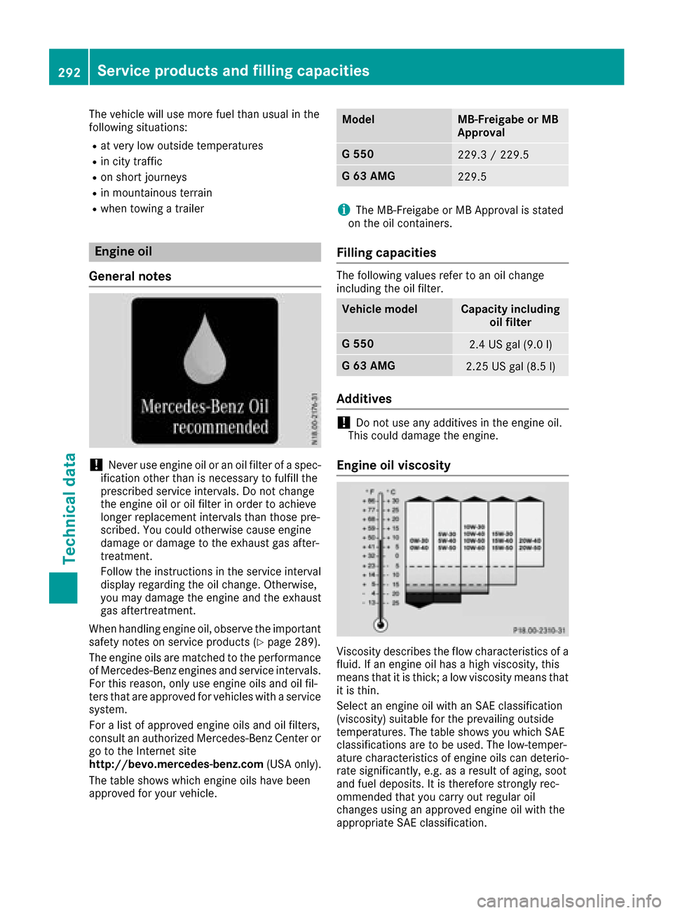
Viscosity describes the flow characteristics of a
fluid. If an engine oil has a high viscosity, this
means that it is thick; a low viscosity means that it is thin.
Select an engine oil with an SAE classification
(viscosity) suitable for the prevailing outside
temperatures. The table shows you which SAE
classifications are to be used. The low-temper-
ature characteristics of engine oils can deterio-
rate significantly, e.g. as a result of aging, soot
and fuel deposits. It is therefore strongly rec-
ommended that you carry out regular oil
changes using an approved engine oil with the
appropriate SAE classification.
292Service products and filling capacities
Technical data