2016 BMW M4 display
[x] Cancel search: displayPage 84 of 228

Fuel gaugeThe vehicle inclination can lead
to fluctuations in the display.
Depending on the equipment,
the arrow next to the petrol
pump symbol shows on which
side of the vehicle the petrol tank flap is.
Information on refuelling, see page 172.
Revolution counter Yellow and red LEDs display
permitted engine speed range.
Permitted engine speed increa‐
ses as engine oil temperature
rises.
Avoid engine speeds in the yellow warning zone if possible.
It is vital to avoid engine speeds in the red
warning zone. In this zone, the fuel supply is in‐
terrupted to protect the engine.
Engine oil temperature▷Cold engine: the pointer is
located at a low temperature
value. Drive with moderate
engine speed and vehicle
speed.▷Normal operating temperature: the needle
is located in the centre or left half of the
temperature display.▷Hot engine: the pointer is located at a high
temperature value. A check control mes‐
sage is also displayed.
Coolant temperature
If the coolant and therefore the engine become
too hot, a check control message is displayed.
Check coolant level, see page 189.
Odometer and trip distance
recorder
Display▷Odometer, arrow 1.▷Trip distance recorder, ar‐
row 2.
Show/reset distance
Press the button.
▷When the ignition is off, the
time, outside temperature
and odometer are displayed.▷When the ignition is on, the
trip distance recorder is re‐
set.
Outside temperature
If the display drops to
+3 ℃/+37 ℉ or lower, a signal
sounds.
A Check Control message is
displayed.
There is an increased risk of black ice.
If the digital speedo is activated, the outside
temperature can be displayed on the on-board
computer.
WARNING
Even at temperatures above
+3 ℃/+37 ℉, there can be an increased danger
of icy roads, e.g. on bridges or on shaded
roads. Danger of accidents. At low tempera‐
tures, adjust the driving style to the weather
conditions.◀
Seite 84ControlsDisplays84
Online Edition for Part no. 01 40 2 964 013 - VI/15
Page 85 of 228
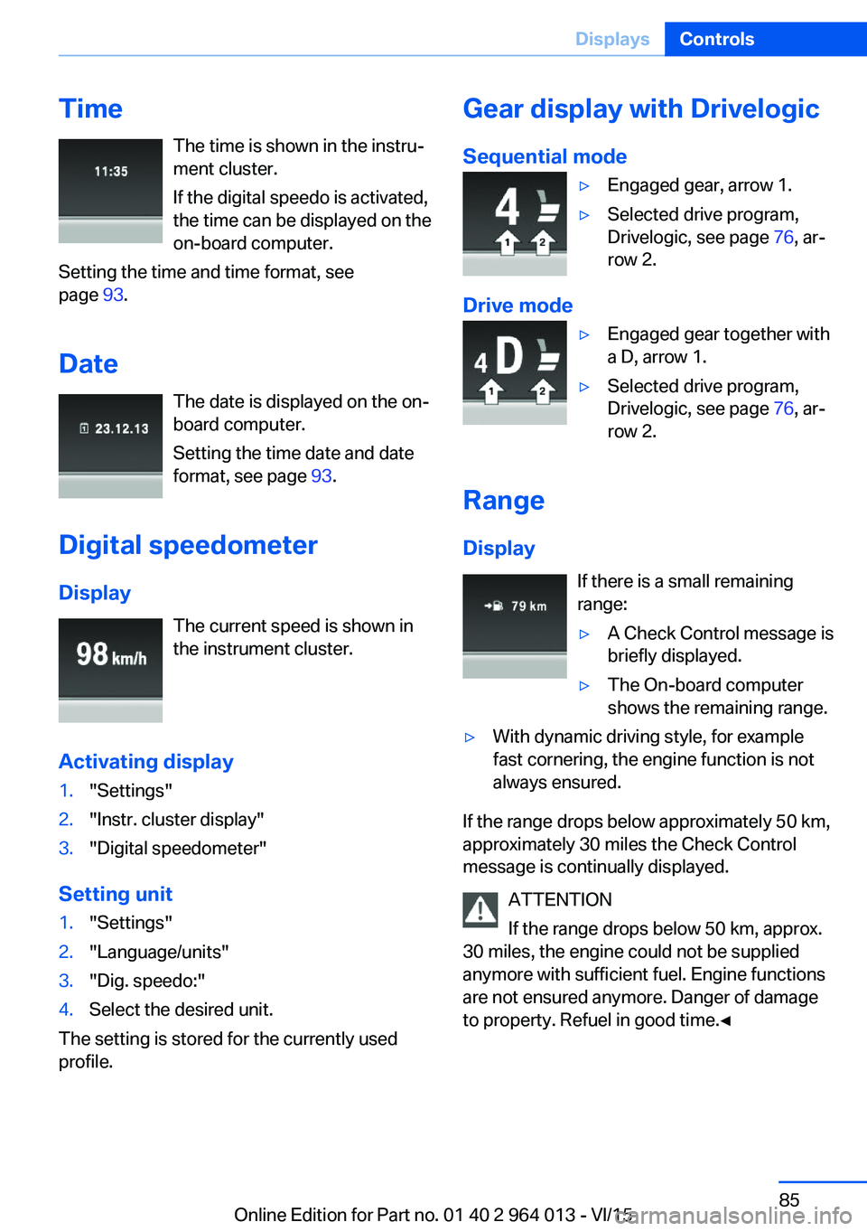
TimeThe time is shown in the instru‐
ment cluster.
If the digital speedo is activated,
the time can be displayed on the
on-board computer.
Setting the time and time format, see
page 93.
Date The date is displayed on the on-
board computer.
Setting the time date and date
format, see page 93.
Digital speedometer
Display The current speed is shown in
the instrument cluster.
Activating display1."Settings"2."Instr. cluster display"3."Digital speedometer"
Setting unit
1."Settings"2."Language/units"3."Dig. speedo:"4.Select the desired unit.
The setting is stored for the currently used
profile.
Gear display with Drivelogic
Sequential mode▷Engaged gear, arrow 1.▷Selected drive program,
Drivelogic, see page 76, ar‐
row 2.
Drive mode
▷Engaged gear together with
a D, arrow 1.▷Selected drive program,
Drivelogic, see page 76, ar‐
row 2.
Range
Display If there is a small remaining
range:
▷A Check Control message is
briefly displayed.▷The On-board computer
shows the remaining range.▷With dynamic driving style, for example
fast cornering, the engine function is not
always ensured.
If the range drops below approximately 50 km,
approximately 30 miles the Check Control
message is continually displayed.
ATTENTION
If the range drops below 50 km, approx.
30 miles, the engine could not be supplied
anymore with sufficient fuel. Engine functions
are not ensured anymore. Danger of damage
to property. Refuel in good time.◀
Seite 85DisplaysControls85
Online Edition for Part no. 01 40 2 964 013 - VI/15
Page 86 of 228
Current fuel consumption
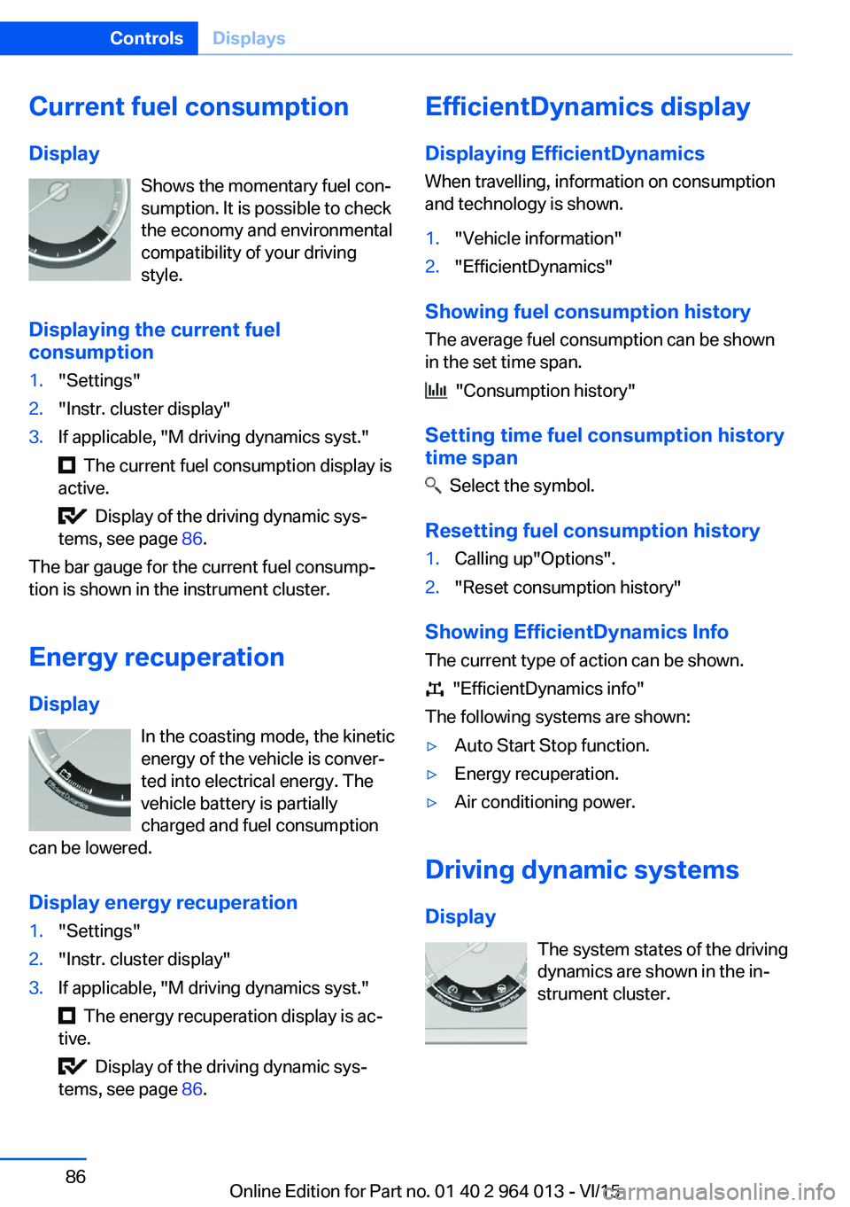
Display Shows the momentary fuel con‐
sumption. It is possible to check
the economy and environmental
compatibility of your driving
style.
Displaying the current fuel
consumption1."Settings"2."Instr. cluster display"3.If applicable, "M driving dynamics syst."
The current fuel consumption display is
active.
Display of the driving dynamic sys‐
tems, see page 86.
The bar gauge for the current fuel consump‐
tion is shown in the instrument cluster.
Energy recuperation
Display In the coasting mode, the kinetic
energy of the vehicle is conver‐
ted into electrical energy. The
vehicle battery is partially
charged and fuel consumption
can be lowered.
Display energy recuperation
1."Settings"2."Instr. cluster display"3.If applicable, "M driving dynamics syst."
The energy recuperation display is ac‐
tive.
Display of the driving dynamic sys‐
tems, see page 86.
EfficientDynamics display
Displaying EfficientDynamics When travelling, information on consumption
and technology is shown.1."Vehicle information"2."EfficientDynamics"
Showing fuel consumption history
The average fuel consumption can be shown
in the set time span.
"Consumption history"
Setting time fuel consumption history
time span
Select the symbol.
Resetting fuel consumption history
1.Calling up"Options".2."Reset consumption history"
Showing EfficientDynamics Info
The current type of action can be shown.
"EfficientDynamics info"
The following systems are shown:
▷Auto Start Stop function.▷Energy recuperation.▷Air conditioning power.
Driving dynamic systems
Display The system states of the driving
dynamics are shown in the in‐
strument cluster.
Seite 86ControlsDisplays86
Online Edition for Part no. 01 40 2 964 013 - VI/15
Page 87 of 228

SymbolsDescriptionM engine dynamics control, see
page 78.Adaptive M chassis, see
page 126.Servotronic, see page 127.
Activating display
1."Settings"2."Instr. cluster display"3.If applicable, "M driving dynamics syst."
The drive dynamics systems display is
active.
Display current consumption, see
page 86, and energy recovery, see
page 86.
Service requirements
Principle The distance to be driven or time to the next
maintenance is displayed briefly after switch‐ ing on the ignition briefly in the instrument
cluster.
The current service requirements can be read
by a service advisor from the remote control.
Display
Detailed information on service
requirements
More detailed information on the scope of
maintenance can be displayed on the Control
Display.
1."Vehicle information"2."Vehicle status"3. "Service requirements"Essential maintenance routines and any
statutory inspections required are dis‐
played.4.Select an entry to display more detailed in‐
formation.
Symbols
Sym‐
bolsDescriptionNo servicing is currently needed.Maintenance or an inspection re‐
quired by law is due soon.Servicing is overdue.
Entering deadlines
Enter deadlines for prescribed statutory in‐
spections.
Ensure that the date and time of the vehicle
are set correctly.
On the Control Display:
1."Vehicle information"2."Vehicle status"3. "Service requirements"4."§ vehicle inspection"5."Date:"6.Adjust the settings.7.Confirm.
The date input is saved.
Automatic Service notification Data on the service status or on statutory in‐
spections for the vehicle are transmitted to the
Service Partner automatically when a service
or inspection is imminent.
It can be checked when the Service Partner
was notified.
Seite 87DisplaysControls87
Online Edition for Part no. 01 40 2 964 013 - VI/15
Page 88 of 228

On the Control Display:1."Vehicle information"2."Vehicle status"3.Call up "Options".4."Last Teleservice Call"
Service history
General Have maintenance work carried out by a Serv‐
ice Partner or a qualified specialist workshop.
Performed maintenance work is recorded in
the vehicle data, see page 191.
The maintenance visits entered can be shown
on the Control Display. Operation is available
as soon as a maintenance visit has been en‐
tered in the vehicle data.
Displaying service history
On the Control Display:
1."Vehicle information"2."Vehicle status"3. "Service requirements"4. "Service history"
Maintenance visits carried out are shown.5.Select an entry to display more detailed in‐
formation.
Symbols
Sym‐
bolsDescriptionGreen: maintenance has been car‐
ried out on time.Yellow: maintenance has been car‐
ried out with a delay.Maintenance has not been carried
out.Shift point indicator
Principle The system recommends the most efficient
gear for the current driving situation.
General
The shift point indicator is active in sequential
mode of the M double clutch transmission and
the manual gearbox.
Information on up or downshifting are dis‐
played on the instrument cluster.
For vehicles without shift point indicator, the
gear engaged is shown.
DisplaysSymbolDescriptionShift up into most efficient gear.Shift down into most efficient gear.
Speed Limit Information with
No Passing Information
Principle
Speed Limit Information Speed Limit Information shows the currently
detected speed limit in the instrument cluster.
The camera in the area of the interior rear-view mirror detects traffic signs at the edge of the
road as well as variable overhead sign posts. Traffic signs with additional symbols, for exam‐
ple, when wet, are also compared with data in‐
ternal to the vehicle, for example the rain sen‐
sor, and displayed, depending on the situation.
The system considers the information saved in
the navigation system and also displays the
Seite 88ControlsDisplays88
Online Edition for Part no. 01 40 2 964 013 - VI/15
Page 89 of 228
speed limits present on unmarked sections of
road.
No Passing Information No Passing Information displays with corre‐
sponding symbols in the instrument cluster no
passing restrictions and their removal detected
by the camera. The system only considers no passing restrictions and lifting the restriction
made known by signage.
Nothing will be displayed in the following situa‐
tions:▷In countries in which no passing is primar‐
ily shown by road markings.▷On routes without signage.▷On railway crossings, lane markings or in
other situations which would not indicate
an unsigned no passing restriction.
Notes
WARNING
The system does not take your personal
responsibility from you when you are estimat‐
ing the visibility conditions and traffic situation.
Danger of accidents. Adapt driving style to the driving conditions. Observe the traffic situation
and intervene actively if the situation warrants
it.◀
Overview
Camera
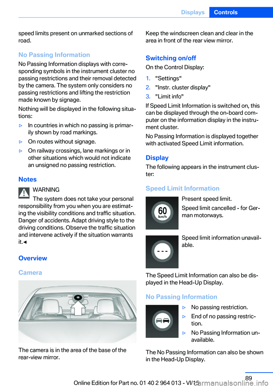
The camera is in the area of the base of the
rear-view mirror.
Keep the windscreen clean and clear in the
area in front of the rear view mirror.
Switching on/offOn the Control Display:1."Settings"2."Instr. cluster display"3."Limit info"
If Speed Limit Information is switched on, this
can be displayed through the on-board com‐
puter on the information display in the instru‐
ment cluster.
No Passing Information is displayed together
with activated Speed Limit information.
Display
The following appears in the instrument clus‐
ter:
Speed Limit Information Present speed limit.
Speed limit cancelled - for Ger‐
man motorways.
Speed limit information unavail‐
able.
The Speed Limit Information can also be dis‐
played in the Head-Up Display.
No Passing Information
▷No passing restriction.▷End of no passing restric‐
tion.▷No Passing Information un‐
available.
The No Passing Information can also be shown
in the Head-Up Display.
Seite 89DisplaysControls89
Online Edition for Part no. 01 40 2 964 013 - VI/15
Page 90 of 228
System limits
The function may be disabled or inaccurate
under certain conditions, for example:▷In thick fog and heavy rain or snow.▷If road signs are obscured by objects.▷If the vehicle is moving too close to the ve‐
hicle ahead.▷With bright oncoming light.▷When the windscreen in front of the rear-
view mirror is covered with condensation,
dirt, stickers, etc.▷Due to possible wrong detections of the
camera.▷If the speed limits saved in the navigation
system are wrong.▷In areas not covered by the navigation sys‐
tem.▷If there are deviations in relation to the nav‐
igation, for example due to changes in the
road routing.▷On overtaking buses or trucks with speed
stickers.▷If traffic signs do not correspond to the
standard.▷During the calibration process of the cam‐
era immediately after the vehicle is sup‐
plied.
Selection lists in the
instrument cluster
Principle Depending on equipment, the following can be
displayed or operated via the buttons and the
knurled wheel on the steering wheel and using
the displays in the instrument cluster and
Head-Up Display:
▷Current audio source.▷Repeat dialling for telephone.▷Activating the voice control system.Display
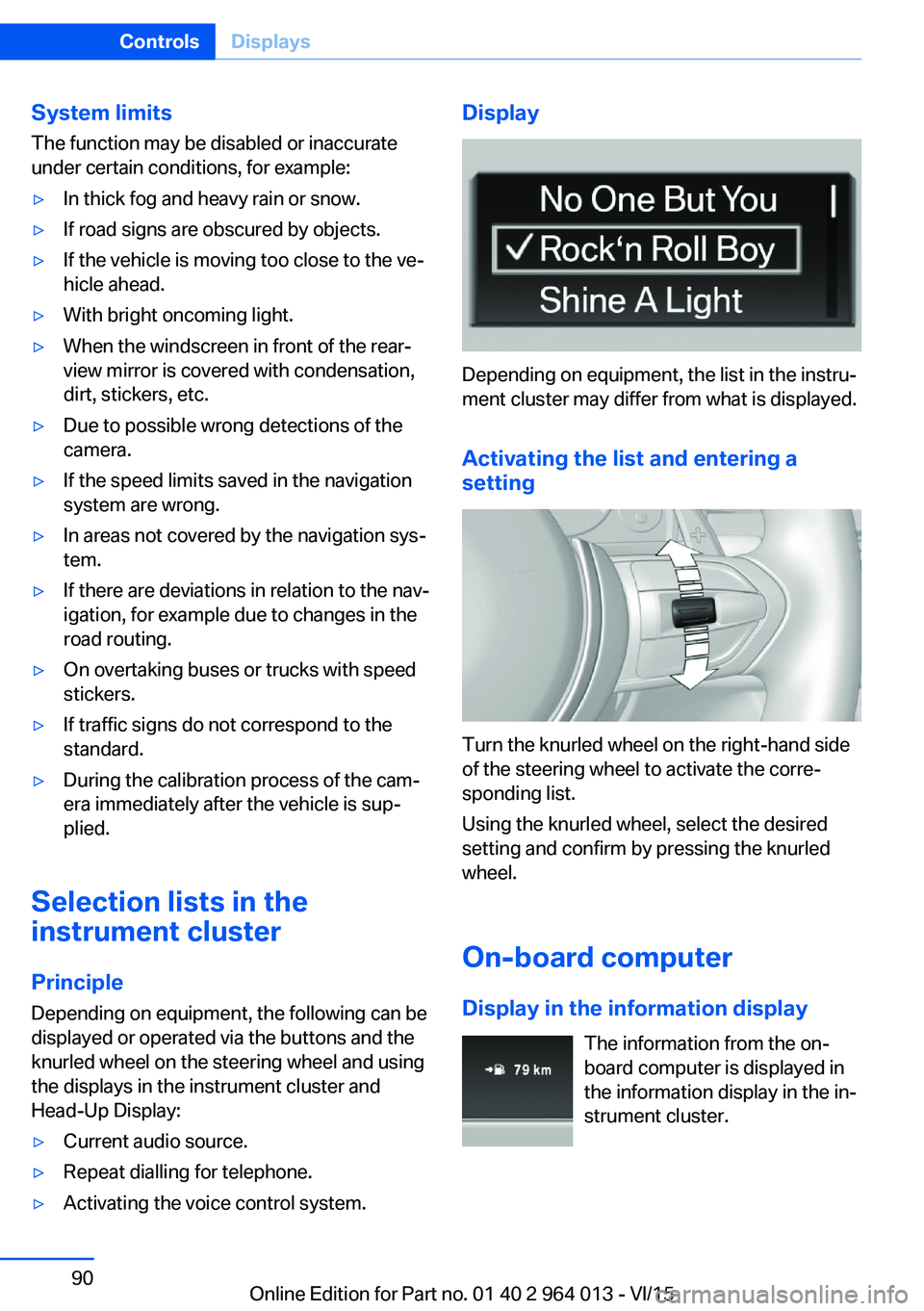
Depending on equipment, the list in the instru‐
ment cluster may differ from what is displayed.
Activating the list and entering a
setting
Turn the knurled wheel on the right-hand side
of the steering wheel to activate the corre‐
sponding list.
Using the knurled wheel, select the desired
setting and confirm by pressing the knurled
wheel.
On-board computer
Display in the information display The information from the on-
board computer is displayed in
the information display in the in‐
strument cluster.
Seite 90ControlsDisplays90
Online Edition for Part no. 01 40 2 964 013 - VI/15
Page 91 of 228
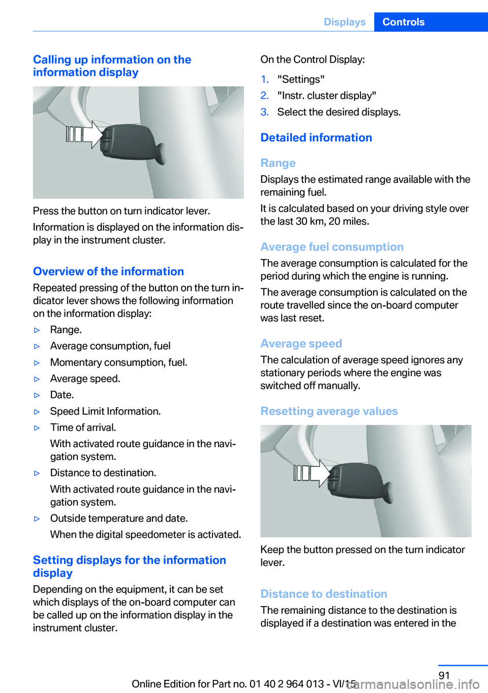
Calling up information on the
information display
Press the button on turn indicator lever.
Information is displayed on the information dis‐
play in the instrument cluster.
Overview of the information
Repeated pressing of the button on the turn in‐
dicator lever shows the following information
on the information display:
▷Range.▷Average consumption, fuel▷Momentary consumption, fuel.▷Average speed.▷Date.▷Speed Limit Information.▷Time of arrival.
With activated route guidance in the navi‐
gation system.▷Distance to destination.
With activated route guidance in the navi‐
gation system.▷Outside temperature and date.
When the digital speedometer is activated.
Setting displays for the information
display
Depending on the equipment, it can be set
which displays of the on-board computer can
be called up on the information display in the
instrument cluster.
On the Control Display:1."Settings"2."Instr. cluster display"3.Select the desired displays.
Detailed information
Range
Displays the estimated range available with the
remaining fuel.
It is calculated based on your driving style over
the last 30 km, 20 miles.
Average fuel consumption
The average consumption is calculated for the
period during which the engine is running.
The average consumption is calculated on the
route travelled since the on-board computer
was last reset.
Average speed
The calculation of average speed ignores any
stationary periods where the engine was
switched off manually.
Resetting average values
Keep the button pressed on the turn indicator
lever.
Distance to destination
The remaining distance to the destination is
displayed if a destination was entered in the
Seite 91DisplaysControls91
Online Edition for Part no. 01 40 2 964 013 - VI/15