Page 217 of 252

.... I.Cl U\"I
N I.Cl ......
Removing the wheel covers/bolt caps
Fig. 165 Changin g a whee l: remo ving the wheel cover
Fig. 166 C h an gin g a w hee l: remov ing t he wh")
.... N
c:i ::J CX)
.... I.Cl U"I
N I.Cl ......
Removing the wheel covers/bolt caps
Fig. 165 Changin g a whee l: remo ving the wheel cover
Fig. 166 C h an gin g a w hee l: remov ing t he wheel bolt caps
Wheel cover*
.. Insert the hook provided with the vehicle tool
kit in the hole in the hub¢
fig. 165.
.. Pull off the decorative wheel cover .
Wheel bolt caps*
.. Push the plastic clip provided with the vehicle
tool kit over the wheel bolt cap until it engages
¢fig . 166.
.. Pull on the plastic clip to remove the cap.
Loosening and tightening the wheel bolts
The wheel bolts must be loosened before raising
the vehicle .
Fig. 167 Ch ang ing a whee l: loose ning the w heel bolts
Emergency assistance
Loosening
.. Inst all the wheel bolt wrench over the wheel
bolt and push it down as far as it wi ll go .
.. Take tight hold of the
end of the wrench hand le
and turn the wheel bolts
counter-clockwise
about one single turn in the direction of arrow
¢fig. 167.
Tightening
.. Insta ll the wheel bolt wrench over the wheel
bolt and push it down as far as it w ill go.
.. Take tight hold of the
end of the wrench hand le
and turn each wheel bolt
clockwise until it is
seated.
A WARNING
-- Do not use force or hurry when changing a
wheel -you can cause the vehicle to slip off
the jack and cause serious personal injuries .
-Do not loosen the wheel bolts more than
one turn
befo re you raise the vehicle with
the jack. -You risk an injury.
(0 Tips
-Never use the hexagonal socket in the han
dle of the screwdr iver to loosen or tighten
the whee l bolts.
- If a wheel bolt is very tight, you may find it
easier to loosen by ca refully pushing down
on the end of the whee l bolt wrenc h with
one foot only. As you do so, hold on to the
car to keep yo ur balance and take care not
to slip.
215
Page 218 of 252

Emerg ency assis ta nce
Raising the vehicle
The vehicle must be li~ed with the jack first be
fore the wheel can be removed .
Fig. 168 Sill panels : mark in gs
Fig. 169 Sill : pos itio nin g th e ve hicle jack
The location of the jack point is indicated by an
indentation on the underside of the vehicle
¢ fig. 168 .
,.. Activate the parking brake to prevent the vehi
cle from rolling unintentionally .
,.. Move the selector lever to the P position.
,.. Find the
m arki ng (imprint) on the sill that is
nearest the wheel that will be changed
c> fig . 168. Behind the marking, there is a li ft
i ng po int
on the sill for the vehicle jack.
,.. Turn the
veh icl e jack located under the lifting
point on the s ill to ra ise the jack until the jaw
c> fig . 169 @cove rs the no tch on the vehicle
c> ,&. ¢0.
,.. Align the vehicle jack so the jaw @covers the
notch and the base plate @ is flat on the floor .
The base plate @ must be
vertical under the
lifting point @.
,.. Install the rod on the vehicle jack : Insert the
rod into the opening on the handwheel. Turn
the rod left or right to secure it .
216
,.. Continue raising the jack with the rod until the
wheel lifts off the ground slight ly.
Position the vehicle jack
only under the designat
ed lifting points on the sill
c> fig. 168. T here is ex
actly
one l ocation fo r each wheel. The jack must
not be positioned at any other location
c> ,1. ¢(D .
So ft gr ound under the jack can cause the ve hicle
to slip off the jack . Always p lace the jack on firm
ground. Use a flat, stab le support if necessary .
Use a non-slip surface such as a rubber mat on a
s lipp ery s urface such as tile.
A WARNING -
-You or your passengers could be injured
while changing a wheel if you do not follow
these safety precautions:
- Position the vehicle jack only at the des ig
nated lifting points and align the jack .
Otherwise, the vehicle jack could slip and
cause an injury if it does not have suffi
cient hold on the vehicle.
- Use only the jack* supplied w ith your veh i
cle to raise the vehicle . If you use a jack
from a different vehicle, your vehicle may
slip off the jack - risk of injury!
- Do not use the jack* supplied with your ve
hicle to raise other vehicles, as these may
slip off the jack - risk of injury!
- A soft or unstab le surface under the jack
may cause the vehicle to slip off the jack.
Always provide a firm base for the jack on
the gro und .
If necessary, use a sturdy
board unde r the jack.
- On hard, slippery surface (such as t iles)
use a rubber mat or similar to prevent the
jac k from slipp ing .
- To help prevent injury to yourself and your
passengers:
- Do not raise the vehicle until you are sure
the jack is securely engaged.
- Passengers must not rema in in the vehicle
when it is jacked up.
- Make sure that passengers wait in a safe
place away from the vehicle and well away
from the road and traffic . .,_
Page 219 of 252

.... I.Cl U\"I
N I.Cl ......
-Make sure jack posit ion is correct , adjust
as necessary and then cont inue to raise
the jack.
- If work has to be done under")
.... N
c:i ::J CX)
.... I.Cl U"I
N I.Cl ......
-Make sure jack posit ion is correct , adjust
as necessary and then cont inue to raise
the jack.
- If work has to be done under the vehicle,
ensure that it is safely supported on su ita
ble stands -risk of injury!
- Never start the engine when the vehicle is
on the jack -risk of accident!
CD Note
Do not lift the vehicle by the sill. Position the
vehicle jack on ly at the designated lifting
points on the sill. Otherwise, your vehicle will
be damaged.
Taking the wheel off/installing the spare
tire
F ollow these instructions step-by-step for chang
ing the wheel .
Fig. 170 C hangin g a w heel: using th e hexagonal s oc ket
(w it h the blade removed ) to turn t he bolt s
Fig. 171 Chan gin g a w hee l: a lig nm ent pin in side the to p
h ol e
After you have loosened all wheel bolts and
raised the vehicle off the ground, remove and re
p lace the whee l as follows:
Em ergen cy a ssis tanc e
Removing the whe el
"' Remove the topmost wheel bolt completely
with the
he xagona l s oc ket in the screwdriver
handle (vehicle too l kit)
c::> fig. 170 and set it
aside on a
clean surface.
.. Screw the threaded end of the
alignment pin
from the tool kit hand-tight into the empty bolt
hole
c::> fig . 171.
"' Then remove the other wheel bolts as described
above .
"' Take off the whee l leaving the alignment p in in
the bolt hole
c::> G) .
Putting on the spare tire
"' Push the spare tire over the alignment pi n
c::>(D .
"' Screw on the whee l bolts and tighten them
slightly u sing the hexagona l socket .
"' Remove the alignment pin and insert and t ight
en the remaining wheel bo lt s lightly like the
rest .
.. Turn the jack hand le count er-clockw ise to lower
the vehicle unti l the jack is fully released .
.. Use the wheel bo lt wrench to tighten all wheel
bolts firmly . Tighten them
in a crisscross pa t
tern,
from one bolt to the (approx imately) op
posite one, to keep the wheel centered .
"' Perform the steps required after chang ing the
wheel
c::> page 214, A~er changing a wheel.
_& WARNING
Do not use the hexagon al soc ket in the screw
driver handle to tighten the wheel bo lts. It is
not possible to tighten the bolts to the re
qu ired torque using the hexagonal socket -
risk of acc ident!
CD Note
When removing or installing the wheel, the
rim could h it the brake rotor and damage t he
rotor. Work carefully and have a second per
son to he lp you.
@ Tips
- When mounting tires with un idirectional
tread de sign
make sure the tread pattern is
pointed the right way
c::> page 218 . 1JJ,,
217
Page 220 of 252

Emergency assistance
- The wheel bolts should be clean and easy to
turn. Check for di rt and cor ros ion on the
mating s urfaces o f both the whee l an d the
h ub. Remove all dirt from t hese surfaces be
fo re remo unt ing t he wheel.
Tires with unidirectional tread design
Tires with unidirectional tread design must be
mounted with their tread pattern pointed in the
right direction.
Using a spare tire with a tread pattern intended for use in a specific direction
W hen us ing a spare ti re with a tread patte rn in
tended for use in a specific d irection, please note
the following:
- The direct ion o f rotat ion is marked by an
arrow
on the s ide of the t ire .
-If the spare tire has to be installed in the incor
rect d irection, use the spare tire only tempora
rily s ince the tire w ill not be ab le to achieve its
optimum pe rformance c haracter istics with re
gard to aq uaplaning, noise and wear .
- We recommend that you pay particular atten
tion to this fact during wet weathe r and that
yo u ad just yo ur speed to match road condi
t ions.
- Replace t he flat t ire with a new one and have it
i ns ta lled on yo ur vehicle as soon as possible to
r esto re t he handling advantages of a unidi re c
t ion al ti re.
Notes on wheel changing
Please read the info rm ation ¢ page 198, New
tires or wheels
i f you are goin g to use a s pare tire
which is d ifferent from the tires on yo ur vehicle.
Afte r you change a tire:
-Check the tire pressure on the spare immedi
ately after installation .
- Have the wheel bolt tightening torque
checked with a torque wrench as soon as pos
sible by your authorized Audi dealer or quali
fied workshop .
218
-With steel and alloy wheel rims, the wheel
bolts are cor rectly tightened at a torque of
105 ft lbs. (140 Nm).
- If you notice that the wheel bolts are corroded
and difficult to turn while changing a tire,
they should be replaced before you check the
t ightening torque.
- Replace the flat tire with a new one and have
it installed on your vehicle as soon as poss i
ble. Remount the wheel cover.
Until then , drive with extra care and at reduced
speeds.
A WARNING
- If you are going to equip yo ur vehicle with
tires or r ims which diffe r from those which
we re facto ry insta lled, the n be su re to read
t he informa tion ¢
page 198, New tires or
wheels.
-Always make sure the damag ed wheel or
eve n a flat tire and t he jack and tool kit ar e
prope rly se cured in t he lu ggage comp art
me nt an d ar e no t loose in the passenge r
compa rtment.
- In an accide nt or sudde n maneuver they
co uld fly forw ard, i njuring an yon e in t he ve
h icle.
- Always s to re d amaged w hee l, jack a nd to ols
secure ly i n t he lug gage co m pa rtm ent. O th
erwise, in an a cci den t or sudden maneuve r
they cou ld fly forwar d, causing injury to pas
senge rs in the ve hicle.
(D Note
D o no t use co mm ercia lly availabl e tire se al
a nts . Ot herwise, t he e lectr ic al components of
the tire p ress ure monitor ing system * will no
l onge r wor k properly and t he sensor for t he
tire pressure monitoring system * w ill have to
be replaced by qualifie d wo rks hop.
-
Page 221 of 252

.... I.Cl U\"I
N I.Cl ......
Fuses and bulbs
Fuses
Replacing fuses
A fuse that has blown will have metal strips that
have burned through .
Fig. 172 Drivers side")
.... N
c:i ::J CX)
.... I.Cl U"I
N I.Cl ......
Fuses and bulbs
Fuses
Replacing fuses
A fuse that has blown will have metal strips that
have burned through .
Fig. 172 Driver's side of the cockpit: fol ding the storage
co mpartme nt dow n
Fig. 173 Engine compartment: removing the fuse pane l
cover
The fuses are located in the driver's side footwell
beh ind th e storage compartment and in the en
gin e compartment .
Preparations
.. Switch the ign ition and all electr ical equipment
off.
.. Check the following table to see which fuse be-
longs to the equipment .
Fuses behind the storage compartment
.. Open the storage compartment .
.. Press the left and right retainers inward and
fold the compartm ent all the way down
¢fig . 172 .
Fuses in the engine compartment
.. Open the hood ¢ page 177.
Fuses and bulbs
.. To release the fuse panel cover, slide both slid
in g reta iners at the left and right forward
¢fig. 173 .
.. Remove the fuse panel cover.
Replacing fuses
The clamp is located below the fuses behind the
storage compartm ent (driver's side) .
.. Fold th is compartment all the way down and
remove the clamp from the holder .
.. Remove the colored plastic clip from the fuse
panel, if necessary . You can dispose of the plas
tic clip .
.. Remove the fuse using the clamp .
.. Replace the blown fuse only with an identical
new one .
.. Insta ll the cover.
Fuse color identification
Color Current rating
in amps
Black 1
Pu rple 3
Light brown 5
Brown 7.5
Red 10
Blue 15
Yellow 20
Whi te or transparent 25
green 30
orange 40
A WARNING
Do not repair fuses and never replace a blown
fuse with one that has a higher amp rat ing .
This can cause damage to the electr ical sys
tem and a fire.
(D Note
If a new fuse burns out again shortly after you
have installed it, have the electrical system
checked as soon as poss ible by an authorized
Audi dealer or authorized Audi Service Facili
ty .
219
Page 222 of 252

Fuses and bulbs
(D Tips
- The following table does not list fuse loca
tions that are not used.
- Some of the equipment listed in the follow
ing tables applies only to certain model ver
sions or certain optional equipment.
Cockpit fuse assignment
The fuse number is stamped into the plastic be
low or above each fuse.
No. Equipment
1 LED headlight (left)
2 LED headlight ( right)
5 LED headlight (left)
6 LED headlight (right)
7 Steering lock
8 Convenience access
9
Airbag control module, AIRBAG OFF indi-
cator light
12 Transmission control module
Air quality sensor for climate contro l sys-
tern, heated w indow washer nozzles,~
button, reverse light button<®>, oil level
13 sensor, climate control system, seat occu-
pant detection system, seat heating , but-
tons in the center console, automatic dim-
ming mirror
Engine control module, transmission con-
trol module, quattro control module,
14
brake lights, electromechanica l steering,
Gateway cont rol module, trailer hitch con-
trol module, ESC contro l module, light
switch, damping control module
Headlight range control module, instru-
ment illuminat ion, headl ights (left, right),
15 diagnostic connector, headlight range con-
trol module, crankcase housing heater, air
flow sensor, socket relay, DC/DC converter
16 Park ing system
17 Parking system rearview camera
18 TV tuner
19 E ngine starter control, DC/DC converter
220
No . Equipment
20
ESC contro l module, climate/heating con-
tro l, special functions interface
21 Selecto r mechanism power supply
22 Interior monitoring
© button, front interior lighting buttons,
23 diagnostic connector, light switch, light/
rain sensor, humidity sensor
25 Headlight power supply
26 Rear window wiper
27 Starter system
28 Infotainment
29
Supply for the park ing system rearv iew
camera and TV tuner
30 Infotainment
31 Infotainment
32 Instrument cluster
33 A utomat ic dimming rearview mirror
36
Cigarette lighter, cockpit/ luggage com-
partment socket
37 Cockpit/rear socket
38 Transmission control module
40 Trailer hitch control module
41 Trailer hitch control module
42 Trailer hitch control module
44 Rear window defogger
45
Electromechanical parking brake control
module
46 Trailer hitch control module
47 quattro control module
48 Aut omat ic lu ggage compartment lid con-
tro l module
so Fan
51
Electromechanical parking brake control
module
52 BCM
53 Fr ont seat heating
54 Panorama roof
55 Sun shade on the panorama roof
56 Adaptive dampers control module
Page 223 of 252

Engine compartment fuse assignment
The fuse number is stamped into the plastic be
low or above each fuse.
No. Equipment
1 Transmiss ion supply
2 ESC
3 Horn
4 DC/DC
converter
5 BCM, battery data module
6 BCM (right)
7 Washer fluid pump
8 BCM (left)
9 Seat adjustment lumbar support
10 Heat oxygen sensor
11 Steering
column lever, multifunction
steering wheel contro ls
1 2 Cell phone adapter
13 Engine control
module
14 Engine control module
15 Gateway
16 Heated oxygen sensor, fuel pump,
engine
components
17 Engine components
18 Fue l pump control module
19 Sound
amplifier, DC/DC converter
20 Clutch pedal sensor, brake light sensor
22 Windshield wipers
23 Water circu
lation pump, auxiliary heater
24 Ignition coils
25 Driver's door
control module (central lock-
ing, window regu lators)
26 Front
passenger's door control module
(centra l locki ng, window reg ulators)
27 Terminal 15 supply
29 Powe r seat adjustment
30 ESC
Fuses an d bulb s
Bulbs
Replacing light bulbs
For your safety, we recommend that you have
your authorized Audi dealer replace any bulbs for
you .
It is becoming increasingly more and more diffi
cult to replace vehicle light bulbs since in many
cases, other parts of the car m ust first be re
moved before you are able to get to the bulb .
T his applies especially to the light bulbs in the
front of your car which you can only reach
through the engine compartment .
Sheet metal and bu lb holders can have sharp
edges that can cause serious cuts, pa rts must be
correctly taken apart and then properly put back
together to help prevent breakage o f parts and
long term damage from water that can enter
housings that have not been properly resealed.
For your safety, we recommend t hat you have
your authorized Aud i dea le r rep lace any bulbs fo r
you, since your dealer has the proper tools, the
correct bulbs and the expertise.
Gas di schar ge la mps (Xe no n light s):
Due to the high electr ical voltage, have the bulbs
rep laced by a qualified technician. Headlights
with Xenon light are identified by the hig h volt
age st icker.
LED headlights* require no maintenance . Please
contact your authorized Audi dea ler if a bulb
needs to be replaced.
_&. WARNING
Changing Xenon lamps wi thout the necessary
equipment can cause serious personal injury .
- Bulbs are pressu rized and can explode when
be ing changed. Potent ial ris k of injury!
- On veh icles equipped with gas disc harge
bu lbs (Xenon light) life-threatening injuries
can resu lt from improper handling of the
high-vo ltage portions of such lamps!
- Only your authorized A udi dealer or quali
fied workshop sho uld change the bulbs in
gas discharge lamps. There are parts with
sharp edges on the openings and on the
221
Page 224 of 252
Fuses and bulbs
bulb holders that can ca use serio us cuts . If
yo u are uncertain about what to do, have
the work performed by an authorized Audi dealer or qualif ied workshop . Serious per
sonal in ju ry may resu lt from imprope rly per·
formed work .
@ Tips
-If you still prefer to rep lace the light bulbs
yourself, be aware that the engine compart ment is a haza rdous a rea to work
in Q page 177 ~&. .
- It is best to ask your authorized A udi dealer
whenever yo u want to change a b ulb.
222
 1
1 2
2 3
3 4
4 5
5 6
6 7
7 8
8 9
9 10
10 11
11 12
12 13
13 14
14 15
15 16
16 17
17 18
18 19
19 20
20 21
21 22
22 23
23 24
24 25
25 26
26 27
27 28
28 29
29 30
30 31
31 32
32 33
33 34
34 35
35 36
36 37
37 38
38 39
39 40
40 41
41 42
42 43
43 44
44 45
45 46
46 47
47 48
48 49
49 50
50 51
51 52
52 53
53 54
54 55
55 56
56 57
57 58
58 59
59 60
60 61
61 62
62 63
63 64
64 65
65 66
66 67
67 68
68 69
69 70
70 71
71 72
72 73
73 74
74 75
75 76
76 77
77 78
78 79
79 80
80 81
81 82
82 83
83 84
84 85
85 86
86 87
87 88
88 89
89 90
90 91
91 92
92 93
93 94
94 95
95 96
96 97
97 98
98 99
99 100
100 101
101 102
102 103
103 104
104 105
105 106
106 107
107 108
108 109
109 110
110 111
111 112
112 113
113 114
114 115
115 116
116 117
117 118
118 119
119 120
120 121
121 122
122 123
123 124
124 125
125 126
126 127
127 128
128 129
129 130
130 131
131 132
132 133
133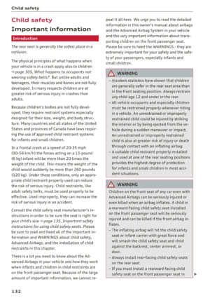 134
134 135
135 136
136 137
137 138
138 139
139 140
140 141
141 142
142 143
143 144
144 145
145 146
146 147
147 148
148 149
149 150
150 151
151 152
152 153
153 154
154 155
155 156
156 157
157 158
158 159
159 160
160 161
161 162
162 163
163 164
164 165
165 166
166 167
167 168
168 169
169 170
170 171
171 172
172 173
173 174
174 175
175 176
176 177
177 178
178 179
179 180
180 181
181 182
182 183
183 184
184 185
185 186
186 187
187 188
188 189
189 190
190 191
191 192
192 193
193 194
194 195
195 196
196 197
197 198
198 199
199 200
200 201
201 202
202 203
203 204
204 205
205 206
206 207
207 208
208 209
209 210
210 211
211 212
212 213
213 214
214 215
215 216
216 217
217 218
218 219
219 220
220 221
221 222
222 223
223 224
224 225
225 226
226 227
227 228
228 229
229 230
230 231
231 232
232 233
233 234
234 235
235 236
236 237
237 238
238 239
239 240
240 241
241 242
242 243
243 244
244 245
245 246
246 247
247 248
248 249
249 250
250 251
251