Page 225 of 252

Emergency situations
General
This chapter is intended for trained emergency
crews and working personnel who have the nec
essary tools and equipment to perform these
operations.
Starting by pushing or
towing
(D Note
Vehicles with an automatic transmission
cannot be started by pushing or towing.
Starting with jumper
cables
If necessary, the engine can be started by con
necting it to the battery of another vehicle .
If the engine should fail to start because of a dis
charged or weak battery, the battery can be con
nected to the battery of
another vehicle, using a
pair of jumper cables to start the engine.
Jumper cables
Use only jumper cables of sufficiently large cross
section
to carry the starter current safely. Refer
to the manufacturer's specifications.
Use only jumper cables with
insulated terminal
clamps which are distinctly marked :
plus(+) cable in most cases colored red
minus(·) cable
in most cases colored black.
A WARNING
Batteries contain electricity, acid, and gas.
Any of these can cause very serious or fatal in
jury. Follow the instructions below for safe
handling of your vehicle's battery.
-Always shield your eyes and avoid leaning
over the battery whenever possible.
-A discharged battery can freeze at tempera
tures just below 32 °F (0 °C). Before con
necting a jumper cable, you must thaw the
Emergency situations
frozen battery completely, otherwise it
could explode .
- Do not allow battery acid to contact eyes or
skin. Flush any contacted area with water immediately.
- Improper use of a booster battery to start a
vehicle may cause an explosion.
- Vehicle batteries generate explosive gases.
Keep sparks, flame and lighted cigarettes
away from batteries.
- Do not try to jump start any vehicle with a
low acid level in the battery .
- The voltage of the booster battery must also
have a 12-Volt rating. The capacity (Ah) of
the booster battery should not be lower
than that of the discharged battery. Use of
batteries of different voltage or substantial
ly different "Ah" rating may cause an explo
sion and personal injury .
- Never charge a frozen battery. Gas trapped
in the ice may cause an explosion.
- Never charge or use a battery that has been
frozen . The battery case may have be weak
ened .
- Use of batteries of different voltage or sub
stantially different capacity (Ah) rating may
cause an explosion and injury. The capacity
(Ah) of the booster battery should not be
lower than that of the discharged battery.
- Before you check anything in the engine
compartment, always read and heed all
WARNINGS
r::!)page 177.
(D Note
-Applying a higher voltage booster battery
will cause expensive damage to sensitive
electronic components, such as control
units, relays, radio, etc.
- There must be no electrical contact between
the vehicles as otherwise current could al
ready start to flow as soon as the positive
(+) terminals are connected.
(D Tips
- The discharged battery must be properly
connected to the vehicle's electrical system. ..,.
223
Page 226 of 252

Emergency situations
When jump starting or charging the bat
tery, never connect the negative ground ca
ble to the battery negative post because the
battery manager system must be able to de
tect the battery's state of charge. Always
connect the negative ground cable to the
negative ground post of the battery manag
er contro l unit.
Use of jumper cables
Make sure to connect the jumper cable clamps in
exactly the order described below!
F ig . 1 74 Engine compar tment: Connectors for jumper ca
bles and charger
N N ~ 9 ::, 00 CXl
F ig. 175 Jump starti ng wit h the battery of another veh icle:
@ discharged vehicle battery,@booster battery
The procedure described below for connecting
jumper cables is intended to provide a jump start for your vehicle.
Vehicle with discharged battery:
• Turn off lights and accessories, move lever of
automatic transmission to N (Neutral) or P
(Park) and set parking brake.
Connect POSITIVE (+) to POSITIVE (+) (red)
• To access the positive terminal, remove the
battery cover
c::> fig. 17 4.
224
1. Connect one end of the red pos itive cable on
the
jump start bolt (D c::> fig. 175 (Bolt under
cover= "positive") of the vehicle to be start
ed @.
2. Connect the other end to the positive termi-
nal @ of the booster battery @.
Connect NEGATIVE (- ) to NEGATIVE (-)
(black)
3. Connect one end of the black negative cable
to the negative term inal @ of the booster
battery @.
4. Connect the other end to the
jump start bolt
@ (Bolt with hex head = "negative") of the
vehicle to be started @.
Starting the engine
• Start the eng ine of the vehicle with the booster
battery @. Run the eng ine at a moderate
speed.
• Sta rt engine w ith discharged vehicle ba ttery @
in the usual manner.
• If the engine fails to start: do not keep the
starter cranking for longer than 10 seconds.
Wait for about 30 seconds and then try again.
• With engine running, remove jumper cables
from both vehicles in the exact
reverse order.
• Fit the cover back onto the battery.
The battery is vented to the outside to prevent
gases from entering the vehicle interior . Make
sure that the jumper clamps are well connected
with their
metal parts in full contact with the
battery terminals.
&_ WARNING
To avoid ser ious personal injury and damage
to the vehicle, heed all warnings and instruc
tions of the jumper cable manufacturer. If in
doubt, call for road service.
- Jumper cables must be long enough so that
the vehicles do not touch .
- When connecting jumper cables, make sure
that they cannot get caug ht in any moving
parts in the engine compartment.
- Do not bend over the batteries - danger of
chemical burns!
Page 227 of 252

.... I.Cl U\"I
N I.Cl ......
-The battery cell lock ing screws must be
t ightened secure ly.
- Befo re yo u check anything in the en gine
compartment, a lways read")
.... N
c:i ::J CX)
.... I.Cl U"I
N I.Cl ......
-The battery cell lock ing screws must be
t ightened secure ly.
- Befo re yo u check anything in the en gine
compartment, a lways read and heed a ll
WARNINGS
¢ page 177.
(D Note
Imp ro per hook -u p of jum pe r cables can r uin
the gene rato r.
-Always con nect POSIT NE
(+ ) to POSITI VE
(+ ), and NEGATIVE( -) to NEGATIVE( -)
ground post of the battery manager contro l
u nit .
- Check that all sc rew p lugs on the batter y
ce lls are screwed in firmly . If not, t ighten
pl ugs prior to connecting clamp on negative
batte ry te rminal.
- Please note t hat the procedure fo r con nect
i ng a jumper cab le as desc ribed above ap
p lies specif ica lly to the case of yo ur vehicle
being jump start ed. Wh en you are giv ing a
ju mp sta rt to anothe r vehicle, do
not con
n ec t t he neg ative (-) ca b le to the negative
( -) t ermina l on the disch arged b attery @
¢
fig. 175. In ste ad , secure ly connec t the
negative( -) ca b le to either a solid me tal
com ponent th at is f irm ly bolted to the e n
gine block o r to t he engine block i tsel f. If
the battery that is be ing c ha rged does not
vent to the outs ide, escap ing batte ry ga s
could ignite and exp lode!
Towing with a tow truck
General hints
Your Audi requires s pecial handling for towing .
The following informa tion is to be used by com
mercia l tow tr uck operators who know how to op
e ra te the ir equip men t safely.
- Ne ver tow your Audi, towing will cause dam
age to the engine and transmission .
- Never wrap the safety chains or winch cables
around the brake lines.
- To prevent unnecessary damage, your Audi
must be transported with a flat bed truck .
Emergency situations
-To load the vehicle on to the flat bed , use the
towing loop found in the vehicle tools and at
tach to the front or rear anchorage
¢ page 225 and ¢ page 226.
A WARNING
A veh icle being towed is not safe for passen
ge rs. Neve r allow a nyo ne to ride in a vehicle
b eing towed, for any reason .
Front towing loop
Only ins tall the front towing loop when i t is
needed .
®
®
-
0 0) N 9 ::>
gi
Fig. 176 Front bum pe r o n th e rig "h t side : remove t he co ver
Fi g. 177 Fron t bum per o n th e right sid e: screw in t he tow
in g loop
The threaded opening for the towing loop i s lo
cate d be hind a cove r on t he rig ht side of the front .,.
225
Page 228 of 252

Emergency situations
bumper. Depending on the version, the cover can
be removed in different ways ¢
fig. 176.
• Version @: Remove the towing loop and the
hook from the veh icle tool kit ¢
page 211. Or
• Version @: Remove the towing loop from the
vehicle tool kit ¢
page 211.
•Version @: Insert the hook into the hole on the
cover and carefully pull off the cover in the di
rection of the arrow ¢
fig. 176. Or
• Ve rsion @: press the cap inward with brief,
forceful pressure
¢fig. 176. The cap w ill loosen
from the bumper.
• Tighten the towing loop in the th readed open
ing until it stops¢
fig. 177 and then tighten it
with a wheel wrench.
• After using, place the towing loop back in the
vehicle tool kit.
A WARNING
If the towing loop is not tightened until it
stops when installing, the threads may be
pulled out when towing the veh icle and that
could cause an accident.
Rear towing loop
Fig. 178 Rear bumper: cover
Fig. 179 Rear bumper: installing the towing loop
226
Vehicles with a towing loop
On vehicles witho ut a factory-installed trailer
hitch*, the rear towing loop is located on the
right side of the bumper .
• Remove the towing loop from the vehicle too l
kit
¢ page 211.
• Press the cap inward with brief, forceful pres
sure¢
fig. 178. The cap will loosen from the
bumper.
• Tighten the towing loop in the threaded open
ing until it stops¢
fig. 179 and then tighten it
w ith a wheel wrench.
• After using, place the tow ing loop back in the
vehicle tool kit.
Vehicles with a trailer hitch*
• Tilt the trailer hitch out.
• Attach the towing bar or the towing cable to
the trailer hitch.
A WARNING
- If the towing loop is not screwed in as far as
it will go, the thread can pull out when the
veh icle is towed - potential risk of an acci
dent.
- If your vehicle has a
trailer hitch* only use a
specia l towing bar to prevent damaging the
ball hitch. These towing bars have been spe
cially designed for trailer towing hitches .
- If your vehicle has a
trailer hitch* use only
special towing cables.
Loading the vehicle onto a flat bed truck
Fig. 180 Vehicle on flat bed truck
~ 0 ::', (IC) m
Page 229 of 252

.... I.Cl U\"I
N I.Cl ......
Front hook up
• Align the vehicle w ith the centerline of the car
earner ramp .
• Attach the winch hook to the front towline")
.... N
c:i ::J CX)
.... I.Cl U"I
N I.Cl ......
Front hook up
• Align the vehicle w ith the centerline of the car
earner ramp .
• Attach the winch hook to the front towline eye
previously installed.
Rear hook up
• Al ign the vehicle w ith the centerline of the car
carr ier ramp .
• Attach the winch hook to the rear towline eye
previously installed.
@ Tips
Check carefully to make sure the hook-up is
secure befo re moving the car up the flatbed
truck ramp.
Raising the vehicle
Lifting with workshop hoist and with floor
jack
The vehicle may only be lifted at the lifting
points illustrated.
Fig. 181 Front lifting point
F ig . 182 Rear lifting point
• Read and heed WARNING¢,&..
I
• Locate lifting points ¢fig.181 and ¢ fig. 182.
Emergency situations
• Adjust lifting arms of workshop hoist or floor
jack to match vehicle lifting points .
• Insert a rubber pad between the floor jack/
workshop hoist and the lifting points .
If you must lift your vehicle with a floor jack to
work underneath, be sure the vehicle is safely
supported on stands intended for this purpose .
Front lifting point
T he lifting point is located on the floor pan rein
forcement about at the same level as the jack
mounting point ¢
fig. 181. Do not lift the vehi
cle at the vertical sill reinforcement .
Rear lifting point
The lifting point is located on the vertical rein
forcement of the lower sill for the on board jack
¢fig . 182.
Lifting with vehicle jack
Refer to¢ page 216.
&_ WARNING
- To reduce the risk of se rious injury and vehi
cle damage.
- Always lift the vehicle on ly at the special
workshop hoist and floor jack lift points il
lustrated ¢
fig. 181 and ¢ fig. 182.
- Failure to lift the vehicle at these points
could cause the vehicle to tilt or fall from
a lift if there is a change in vehicle weight
distribution and balance . This might hap
pen, for example, when heavy compo
nents such as the engine block or trans
mission are removed.
- When remov ing heavy components like
these, anchor vehicle to hoist or add corre
sponding weights to maintain the center of
gravity. Otherw ise, the vehicle might tilt or
slip off the hoist, causing serious personal
injury .
([) Note
-Be aware of the following points before lift-
ing the vehicle: ..,_
227
Page 230 of 252
Emergency situations
-The vehicle should never be lifted or
jacked up from underneath the engine oil
pan, the transmission housing, the front
or rear axle or the body side members.
This could lead to serious damage.
- To avoid damage to the underbody or
chassis frame, a rubber pad must be in
serted between the floor jack and the lift
points .
- Before driving over a workshop hoist,
check that the vehicle weight does not
exceed the permissible lifting capacity of
the hoist .
- Before driving over a workshop hoist, en
sure that there is sufficient clearance be
tween the hoist and low parts of the ve hicle.
228
Page 231 of 252

.... I.Cl U\"I
N I.Cl ....
Technical data
Vehicle identification
F ig. 183 Location on d river s side dash panel: Vehicle Iden·
ti fic ation Number (VlN) p late")
.... N
c:i ::J CX)
.... I.Cl U"I
N I.Cl ....
Technical data
Vehicle identification
F ig. 183 Location on d river 's side dash panel: Vehicle Iden·
ti fic ation Number (VlN) p late
XXXXX XX -X -XXXX XXX XX
CD+ ~t :1:: xxxxxxxx xx x xxxxxxxx
TVP/fffl XXX XXX
XX XXXXXXX XX X X xx
XXX KW XXX
®i ~:J·f lfils~~ XXXX XXX XXX
®-+ ~N:a=i~l xxxx ; xxxx xxx ; xx
II. · AUSS, I OPTIONS
,__ __
EO A 7D5
2EH J0Z
3FC
FOA
TL6 3KA
lXW
7T6 CV7
3L4
lSA
4UB 6XM 5SG
llB l AS
SMU 7Xl
9G3 0G7 0YH
8EH
Ul A X 98
803 908 824
7K0 4X3 2K2
4KC 3Y0 413
7GB 01A
5RW
18 A
0JF
Q Z7
020
502
4G0
XX . X XX X XX X XXXX
Fig. 184 Inside the luggage compartment: Vehicle identifi
cat ion labe l
Veh icle Identification Number (VlN )
The Vehicle Identification Number is located in
different p laces :
- under the windshield on the driver's side
¢ fig . 183.
-in the radio or in the MMI*: !CARI function but
ton
> ( Car ) Systeme * control button > Servic
ing
& checks > VIN number .
-on the vehicle identification label.
Technical data
Vehicle identification label
The veh icle identification label is located in the
luggage compartment near the battery.
T he label¢
fig. 184 shows the following vehicle
data:
(D Vehicle Identification Number (VIN)
@ Vehicle type, eng ine output, transm ission
@ Engine and transmission code
@ Paint number and interior
® Optional equipment numbers
T he information of the veh icle identification label
can also be found in your Warranty
& Mainte
nance booklet.
Safety compliance sticker
The safety compliance sticker is your assurance
that your new vehicle complies w ith all applicable
Federal Motor Vehicle Safety Standards which
were in effect at the time the vehicle was manu
factured. You can find this sticker on the door
jamb on the driver 's side. It shows the month and
year of production and the vehicle identification number of your vehicle (perforation) as well as
the Gross Vehicle Weight Rat ing (GVWR) and the
Gross Axle Weight Rating (GAWR).
H igh voltage warning label
The high voltage warning label is located in the
engine compartment next to the engine hood re
lease. The spark ignition system complies with
the Canadian standard ICES-002.
Weights
Gross Vehicle Weight Rating
The Gross Vehicle Weight Rating (GVWR), and
the Gross Axle Weight Rating (GAWR) for front
and rear are listed on a sticker on the door jamb
on the driver 's side.
The Gross Vehicle Weight Rating includes the
weight of the basic vehicle plus full fuel tank, oil
and coolant, plus maximum load, which includes
passenger weight (150 lbs/68 kg per des ignated
seating position) and luggage weight
c:> .&, . .,.
229
Page 232 of 252

Tech nical data
Gross Axle Weight Rating
The G ross Ax le We ight Rating is the max imum
load that can b e applied at each axle of the vehi
cle ¢& .
Vehicle capacity weight The vehicle capacity we ight (max . load) is l isted
on the d river's side 8-p illar.
Roof weight
The max imum perm issible roof weight is
1 65 lb
(75 kg ). The roof weight is the total of the
weight of the roof rack, the attachments and the cargo you are carrying.
.8, WARNING
- T he ac tual Gross Axle Weight Rating a t the
front and rear axles shou ld not exceed t he
permissible weights, and their comb ination
must not excee d the Gross Ve hicle Weight
Rating .
- Exceeding pe rm issible weight ratings can
result in ve hicle damage, accidents and per
sonal in jury.
(D Note
- T he vehicle capacity weight figures app ly
when the loa d is distrib uted even ly in the
vehicle (passengers and luggage) . When
transporting a heavy load in the luggage
compartment, carry t he load as near to the
rear axle as possible so that the vehicle's
handling is not impaired.
- Do not exceed the maximum permissible
axle loads o r the maximum gross vehicle
weight . Always remember tha t the vehicle 's
handling w ill be affected by the extra load.
T herefo re, adjust yo ur speed accordingly .
- Always obse rve local reg ulations .
Dimensions
Length in (mm) 172.8 (4388)
Width in (mm) 72
.0 (1831)
230
Width (across mir- i
n (mm) 79.4 (2019)
ro rs)
H eight (u nloa ded)a )
in (mm)
62 .5 (1590)
a) The he ig ht of th e vehicl e depend s on t he tire s an d the sus
p en sion .
When dr iving up steep ramps, on rough roads,
over curbs, etc. it is important to remember that
some parts of your veh icle, s uch as spoilers o r ex
haust system components, may be close to the
ground. Be c arefu l not to d amage them.
Capacities
Fue lta nk:totalca- gal (liters) 16.9 (64 .0)
pacity
Windshield washer q
uarts (lit-
4 .8 (4 .5)
fluid container ers)
 1
1 2
2 3
3 4
4 5
5 6
6 7
7 8
8 9
9 10
10 11
11 12
12 13
13 14
14 15
15 16
16 17
17 18
18 19
19 20
20 21
21 22
22 23
23 24
24 25
25 26
26 27
27 28
28 29
29 30
30 31
31 32
32 33
33 34
34 35
35 36
36 37
37 38
38 39
39 40
40 41
41 42
42 43
43 44
44 45
45 46
46 47
47 48
48 49
49 50
50 51
51 52
52 53
53 54
54 55
55 56
56 57
57 58
58 59
59 60
60 61
61 62
62 63
63 64
64 65
65 66
66 67
67 68
68 69
69 70
70 71
71 72
72 73
73 74
74 75
75 76
76 77
77 78
78 79
79 80
80 81
81 82
82 83
83 84
84 85
85 86
86 87
87 88
88 89
89 90
90 91
91 92
92 93
93 94
94 95
95 96
96 97
97 98
98 99
99 100
100 101
101 102
102 103
103 104
104 105
105 106
106 107
107 108
108 109
109 110
110 111
111 112
112 113
113 114
114 115
115 116
116 117
117 118
118 119
119 120
120 121
121 122
122 123
123 124
124 125
125 126
126 127
127 128
128 129
129 130
130 131
131 132
132 133
133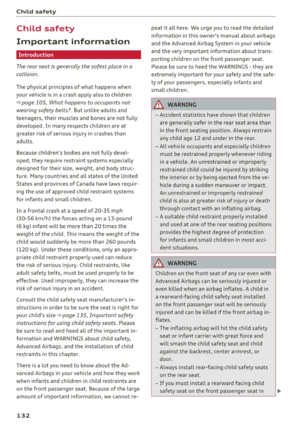 134
134 135
135 136
136 137
137 138
138 139
139 140
140 141
141 142
142 143
143 144
144 145
145 146
146 147
147 148
148 149
149 150
150 151
151 152
152 153
153 154
154 155
155 156
156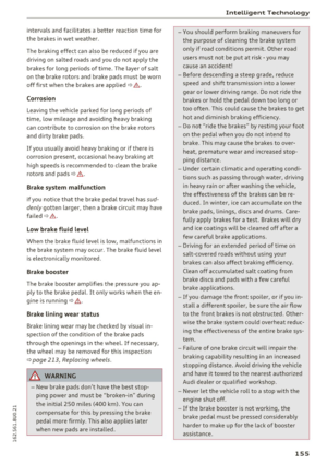 157
157 158
158 159
159 160
160 161
161 162
162 163
163 164
164 165
165 166
166 167
167 168
168 169
169 170
170 171
171 172
172 173
173 174
174 175
175 176
176 177
177 178
178 179
179 180
180 181
181 182
182 183
183 184
184 185
185 186
186 187
187 188
188 189
189 190
190 191
191 192
192 193
193 194
194 195
195 196
196 197
197 198
198 199
199 200
200 201
201 202
202 203
203 204
204 205
205 206
206 207
207 208
208 209
209 210
210 211
211 212
212 213
213 214
214 215
215 216
216 217
217 218
218 219
219 220
220 221
221 222
222 223
223 224
224 225
225 226
226 227
227 228
228 229
229 230
230 231
231 232
232 233
233 234
234 235
235 236
236 237
237 238
238 239
239 240
240 241
241 242
242 243
243 244
244 245
245 246
246 247
247 248
248 249
249 250
250 251
251