Page 241 of 278
 ,....,
I.Cl U\"I ,....,
I.Cl ,....,
.,. Always store the vehicle tool kit, the jack* and
the replaced tire in the luggage compartment
e::> page 126 .
Stowing the")
,....,
N
0
""' CX) ,....,
I.Cl U"I ,....,
I.Cl ,....,
.,. Always store the vehicle tool kit, the jack* and
the replaced tire in the luggage compartment
e::> page 126 .
Stowing the inflatable spare tire
.,. Release the air by unscrewing the valve stem .
.,. Screw the valve stem back in afterwards.
.. Wait a few hours before placing the whee l in
the spare wheel well
e::> .&_.
.. Secure the wheel with the large screw.
.,. Fold the cargo floor back down.
After using the infl atabl e spare w hee l
The inflatable spare tire can be re-used as long as
it is not damaged and is not worn down to the
tread wear indicators~ .&..
When you le t the air out of the infla table spare
tire, it does not assume its folded shape again for
several hours. Until then, it cannot be placed
back in the spare wheel well and stowed securely .
A WARNING
-Never use the spare tire if it is damaged or if
it is worn down to the tread wear indicators.
- If the inflatable spare tire is more than 6
years old, use it on ly in an emergency and
with extreme caut ion and careful driving.
- The inflatab le spare tire is intended only for
temporary and short-term use. It shou ld be
replaced as soon as poss ible with the nor
mal wheel and tire.
- The tire pressure value for the inflatable
spare tire is located on the driver's s ide B
pillar
e::> page 227, fig. 190.
- Maximum perm iss ible speed is 50 mph
(80 km/h).
- Avoid full-throttle accelerat io n, heavy brak
ing, and fast corneri ng.
- When the air is let out of the inflatable
spare wheel, it does not assume its folded
shape for several hours. Until then, it can not be placed back in the spare wheel well
and stowed secu rely .
- Never drive with more than one inflatable
spare tire .
- For technical reasons ., the use of tire chains
on the inf latab le spare tire is not perm itted.
Em ergen cy a ssis tanc e
If it is necessary to drive with tire chains,
the inflatable spare wheel must be mounted
on the rear a xle in the event of a flat in a
front tire. The newly available rear whee l
must then be installed in place of the front
wheel wi th the flat t ire. Installing the t ire
chai n befo re mounting the whee l and tire is
re comme nded.
- L oose items in the passenger compartment
can cause se rious personal injury during
ha rd br aking or i n an accident . Never store
the inflatable spare tire or jack * and too ls in
the passenge r compartment .
(D Note
- The inflatable spa re t ire has been deve loped
specifically fo r thi s ve hicle mode l.
It must
not be exchanged or used for other vehicle
mode ls. S imilar ly, inf latab le tires from oth
er veh icle mode ls must not be used.
- Normal summer or w inte r tires must not be
installed on the inflatable t ire rim.
Inflating inflatable spare
tire
Applies to vehicles: wit h inflatable s pare tir e
Fig. 19 7 Luggage compartm ent: compressor
.. Remove the cover for the vehicle tools and re
move the compressor . For some vehicle mod
els, the compressor is located in a holder under
the spare tire.
.. Unscrew the valve stem from the spare tire.
.,. Screw the t ire filler hose from the compressor
fi rmly onto the valve of the spare tire .
.,. Insert the p lug from t he comp ressor into a
soc ket of the veh icle
e:> page 64 .
.,. Sw itch t he comp ressor on. .,,.
239
Page 242 of 278

Emergency assistance
"'Let the compressor run until the va lue specified
on the tire pressure label is reach ed
¢ page 227, fig. 191 . Switch the compressor
off after running for 12 minutes at the mos t -
danger of overheating!
A WARNING
The compressor and the tire filler hose can become extremely hot while they are running
- danger of burns!
CD Note
Switch the compressor off after running for
12 minutes at the most -danger of overheat
ing! Allow the compressor to cool down for a
few minutes before you use it again.
Replacing wheels
Before changing a wheel
Observe the following precaut ions for your own
and your passenger's safety when changing a
wheel.
"' After you experience a tire failure, pull the car
well away from moving traffic and try to reach
level ground before you stop ¢.&_ .
"' All passengers shou ld
leave the car and move
to a safe location (for instance, behind the
guardrail) ¢.&_ .
"' Engage the
parking brake to prevent your vehi
cle from rolling unintentionally ¢&_ .
"' Sh ift into
1st gear on vehicles w ith manual
transmission, or move the
selector lever to the
P position
on vehicles with automatic transmis
sion .
"' If you are towing a trailer: unhitch the trailer
from your vehicle.
"' Take the
jack¢ page 237 and the spare tire
¢ page 238 out of the luggage compartment .
A WARNING
You or your passengers could be injured wh ile
chang ing a wheel if you do not follow these
safety precautions :
- If you have a flat tire, move a safe distance
off the road . Turn off the engine, turn the
240
emergency flashers on and use other warn
ing devices to alert other motorists.
- Make sure that passengers wait in a safe
place away from the vehicle and well away
from the road and traffic.
- To help prevent the vehicle from moving
suddenly and possibly slipping off the jack,
always fully set the parking brake and block
the wheel diagonally opposite the wheel be ing changed with the folding chocks or oth
er objects . When one front whee l is lifted
off the ground, placing the Automat ic
T ransmission in "P" (Par k) w ill
not prevent
the vehicle from moving.
- Before you change a wheel, be sure the
ground is level and firm . If necessary, use a
sturdy board under the jack.
- Always store the vehicle tool kit, the jack*
and the replaced tire in the luggage com
partment
¢ page 126.
CD Note
If you a re changing the wheel on a steep in
cline, use a rock or similar object to block the
opposite wheel to prevent the vehicle from
moving.
(D Tips
Obey all laws.
Changing a wheel
When you change a wheel, follow the sequence
described below step-by-step and in exactly that
order .
1. Remove the decorative wheel cover* or the
wheel bolt caps* . For more details see also
¢ page 241, Decorative wheel covers or
¢ page 241, Wheels with wheel bolt cops.
2. Loosen the wheel bolts ¢page 242.
3. Locate the proper mounting point for the
jack and align the jack below that point
¢ page 242.
4. Lift the car with the jack¢ page 242.
5. Remove the wheel with the flat tire and then
install the
spare tire ¢page 243.
6. Tighten all whee l bolts lightly .
Page 243 of 278
 ,....,
I.Cl U\"I ,....,
I.Cl ,....,
7. Lower the vehicle with the jack .
8 . Use the wheel bolt wrench and
firmly tighten
all wheel bolts in a crisscross pattern")
,....,
N
0
""' CX) ,....,
I.Cl U"I ,....,
I.Cl ,....,
7. Lower the vehicle with the jack .
8 . Use the wheel bolt wrench and
firmly tighten
all wheel bolts in a crisscross pattern
c>page242.
9. Replace the decorative wheel cover* or the
wheel bolt caps* .
A WARNING
Always read and follow all WARNINGS and in
formation
¢ &. in Raising the vehicle on
page 243
and c> page 244.
After changing a wheel
A wheel change is not complete without the do
ing the following .
.,. Always store the vehicle tool kit, the jack*, and
the replaced tire in the luggage compartment
c>page 126.
.,. Check the tire pressure of the spare tire as soon
as possible.
.,. As soon as possible, have the
tightening tor·
ques
on all wheel bolts checked with a torque
wrench. The correct tightening torque is 90 ft lbs. (120 Nm).
.,. Have the flat tire
replaced as soon as possible.
@ Tips
- If you notice that the wheel bolts are cor
roded and difficult to turn while changing a
tire, they should be replaced before you
check the tightening torque.
- D rive at reduced speed until you have the
tightening torques checked.
Emergency assistance
Decorative wheel covers
Applies to vehicles: with decorative wheel covers
T he decorative wheel covers must be removed
first to access the wheel bolts.
Fig. 198 Changing a whee l: re moving the wheel cover
Removing
.,. Insert the hook provided with t he vehicle tool
kit in the hole in the hub.
.,. Pull off the
decorative wheel cover c> fig. 198 .
Wheels with wheel bolt caps
Applies to vehicles: with wheel bolts w,th caps
The caps must be removed first from the wheel
bolts before the bolts can be unscrewed .
Fig. 199 Changing a wheel: removing the wheel bolt cap s
Removing
.,. Push the plastic clip provided with the vehicle
too l kit over the wheel bolt cap un til it engages .
.,. Pull on the
plastic clip to remove the cap
c>fig. 199 .
Refitting
.,. Place the caps over the whee l bolts and push
them back on.
241
Page 244 of 278

Emergency assistance
The caps are to protect and keep the whee l bolts
clean.
Loosening and tightening the wheel bolts
The wheel bolts must be loosened before raising
the vehicle.
Fig . 200 Changing a wheel: loosening the wheel bolts
Loosening
• Install the wheel bolt wrench over the wheel
bolt and push it down as far as it will go.
• Take tight hold of the
end of the wrench handle
and turn the wheel bolts
counter-clockwise
about one single tur n in the direction of ar row
¢fig. 200.
Tightening
• Install the wheel bolt wrench over the wheel
bolt and push it down as far as it will go.
• Ta ke tight hold of the
end of the wrench handle
and turn each whee l bolt
clockwise until it is
seated.
_& WARNING
- Do not use force or hurry when changing a
wheel -you can cause the vehicle to slip off
the jack and cause serious personal injuries.
-Do not loosen the whee l bolts more than
one turn
before you raise the vehicle with
the jack. -You risk an injury .
(D Tips
-Never use the hexagonal socket in the han
dle of the screwdriver to loosen o r tighten
the wheel bolts.
- If a whee l bolt is very tight, you may find it
easier to loosen by carefully push ing down
242
on the end of the whee l bolt wrench with
one foot only. As you do so, hold on to the
car to keep your balance and take care not
to slip.
Raising the vehicle
The vehicle must be lifted with the jack first be
fore the wheel can be removed.
Fig. 201 Sill panels: marking s
Fig. 202 Sill: positio ning the vehicle jack
The location of the jack point is indicated by an
i ndentation on the underside of the vehicle
¢fig. 201.
• Activate the parking brake to prevent the vehi
cle from rolling unintentionally.
• Shift into
1st gear on vehicles with manua l
transmission or move the selector lever to the P
position on vehicles with automatic transmis
sion.
• Find the
marking (imp rint) on the sill that is
nearest the wheel that will be changed
¢ fig. 201. Behind the marking, there is a lift
ing point on the sill for the vehicle jack.
• Turn the
vehicle jack located under the lifting
point on the sill to raise the jack until the jaw
¢ fig. 202@covers the notch on the veh icle
¢ ~ ¢©. ~
Page 245 of 278
 ,....,
I.Cl U\"I ,....,
I.Cl ,....,
.. Align the vehicle jack so the jaw@ covers the
notch and the base plate @ is flat on the floor.
The base plate @ must be")
,....,
N
0
""' CX) ,....,
I.Cl U"I ,....,
I.Cl ,....,
.. Align the vehicle jack so the jaw@ covers the
notch and the base plate @ is flat on the floor.
The base plate @ must be
vertical under the
lift ing point @.
.. Install the rod on the vehicle jack : Insert the
rod into the opening on the handwheel. Turn
t h e rod left or right to secure it .
.. Cont inue raising the jack with the rod until the
wheel lifts off the ground slightly .
Position the vehicle jack
only under the designat
ed lifting points on the sill~
fig. 201. There is ex
actly
one locat ion for each wheel. The jack m ust
n ot be positioned at any other location~ &~© -
Soft gro und under the jack can cause the veh icle
to slip off the jack. Always place the jack on firm
g round . U se a flat, stable support if necessary .
Use a non-slip surface such as a r ubber mat on a
slippery surfa ce such as tile.
& WARNING
- Yo u or your passengers could be injured
whi le changing a wheel if you do not follow
these safety precautions:
- Position the veh icle jack only at the desig
nated lifting points and align the jack .
Othe rw ise, the vehicle jac k cou ld slip and
cause an injury if it does no t have suffi
cient hold on the vehicle .
- A soft or uns table s urface unde r the jack
may c ause the vehicle to slip off the jac k.
Always p rovide a firm base for the jack on
the ground . If necessary, use a sturdy
board under the jack .
- O n ha rd, slippery surface (such as tiles)
use a rubber mat or similar to prevent the
jack from slipping.
- To help prevent injury to yourself and yo ur
passengers:
- Do not ra ise the vehicle unt il you are sure
the jack is securely engaged.
- Passengers must not remain in the vehicle when it is jacked up.
- Make sure that passengers wait in a safe
place away from the vehicle and well away
from the road and traff ic.
Em ergen cy a ssis tanc e
-Make sure jack position is correct, adjust
as necessary and then continue to raise
the jack.
(D Note
Do not lift the vehicle by the si ll. Pos ition the
vehicle jack on ly at the designated lifting
po ints on the sill. Otherwise, your veh icle w ill
be damaged.
Taking the wheel off /installing the spare
tire
Follow these instructions step-by-step for chang
ing the wheel.
F ig . 203 Chang ing a w hee l: us ing the screwdriver handle
(with the blade removed) to turn th e bolts
Fi g. 20 4 Cha ngin g a w heel: alignme nt pin ins ide the top
h ole
After yo u have loosened all wheel bolts and
raised the vehicle off the ground, remove and re
place the wheel as follows:
Removing the wheel
.. Remove the topmost wheel bo lt completely
w ith the
hexagon al so cket in t he sc rewdrive r
handle (ve hicl e too l kit) ~
fig. 203 and set it
aside on a
clean surface.
243
Page 246 of 278

Emergency assistance
"' Screw the threade d end of the alignment pin
from the tool kit hand-tight into the empty bolt
ho le ¢
fig . 204 .
"'Then remove the other wheel bolts as described
above.
"' Take off the wheel leav ing the a lignment pin in
the bol t ho le ¢ (D .
Putting on the spare tire
"'all road : Inf late the inflatable spare tire
¢ page239
"'Push the spare tire over the alig nment pin .
"' Screw on the wheel bo lts and tighten them
slightly using the hexagonal socke t.
"' Remove the a lignment pin and inse rt and tig ht
en the rema ining whee l bol t slightly like the
r e st .
"'T urn the jack handle counte r-clo ckwise to lower
the ve hicl e until the jack is fully re leased .
"' Use the whee l bolt wrench to tighten all whee l
bo lts firmly ¢
page 242. Tighten them in a
crisscross pattern,
from one bolt to the (ap
prox imately) opposite one, to keep the wheel
cente red .
"' Perform the steps req uired afte r changing th e
whee l¢
page 241, After changing a whe el.
The hexago nal soc ket makes it eas ier to remove
the wheel bolts from t he rim . Care shou ld be tak
e n when remov ing t he revers ible b lade .
([) Note
When removi ng or installing the wh ee l, the
r im cou ld hit the brake ro tor and damage th e
rotor . Work ca refull y and have a secon d per
so n t o help yo u.
@ Tips
- W hen mounting tir es w ith unidirectional
tread design
mak e sure th e tread pa ttern is
p oin te d t he r igh t way ¢
page 2 44.
-The w heel bol ts should b e cle an an d easy to
t urn. Check for d irt and cor ros io n on the
m at ing s urf ac es o f both t he whee l and the
hu b. Rem ove a ll di rt from th ese sur fac es b e
f o re remo untin g t he wheel.
244
- Do not use the hexagonal socke t in the
sc rewdrive r hand le to loose n or tig hten the
wheel bol ts .
Tires with unidirectional tread design
Tires with unidirectional tread design must be
mounted with their tread pattern pointed in the
right direction.
Using a spare tire with a tread pattern
intended for use in a specific direction
When using a spare tire w ith a t read pattern in
tended for use in a specif ic direction, please note
the following:
- The direction of rotation is marked by an
arrow
on the side of the tire.
- If the spare tire has to be inst alled in the inco r
rect direction, use the spare tire on ly tempora
r il y since the tire will not be a ble to ac hieve its
optimum performance characterist ics with re
gard to aquaplan ing, no ise and wear.
- We recommend that you pay part icu lar atten
tion to th is fact d uring wet weather and that
you adjust your speed to matc h road condi
tions .
- Rep lace the flat tire w ith a new one and have it
installed o n your veh icle as soon as possib le to
restore the hand ling advan tages of a un id irec
t ional tire.
Notes on wheel changing
Please re ad th e inf ormati on ¢ page 224, New
t ires or w heels
if yo u are going to use a sp are tire
which is d iffe rent from the t ires on your ve hicle.
Af ter yo u cha nge a tire :
-Check the tire pressure on the spare immedi
ately after installation .
- Have the wheel bolt t ightening torque
checked with a torque wrench as soon as pos
sible by your authorized Audi dealer or quali
fied workshop.
- With steel and alloy wheel rims, the wheel
bolts are correctly tightened at a torque of 90
ft lb s. (120 Nm). ..,_
Page 247 of 278
 Lil ,...., <J:) .....
-If you notice that the wheel bolts are corroded
and difficult to turn while changing a tire,
they should be replaced before")
..... N
0 ::..:: co ,....,
-If you notice that the wheel bolts are corroded
and difficult to turn while changing a tire,
they should be replaced before you check the
tightening torque.
- Replace the flat tire with a new one and have
it installed on your vehicle as soon as possi
ble. Remount the wheel cover.
Until then, drive with extra care and at reduced
speeds.
A WARNING
- If you are going to equip your vehicle with tires or rims which differ from those which
were factory installed, then be sure to read
the information
c> page 224, New tires or
wheels.
-
- Always make sure the damaged wheel or
even a flat tire and the jack and tool kit are
properly secured in the luggage compart
ment and are not loose in the passenger
compartment.
- In an accident or sudden maneuver they
could fly forward, injuring anyone in the ve
hicle.
-Always store damaged wheel, jack and tools
securely in the luggage compartment. Oth
erwise, in an accident or sudden maneuver
they could fly forward, causing injury to pas
sengers in the vehicle.
(D Note
Do not use commercially available tire seal
ants. Otherwise, the electrical components of
the tire pressure monitoring system* will no
longer work properly and the sensor for the
tire pressure monitoring system* will have to
be replaced by qualified workshop .
Emergency assistance
245
Page 248 of 278

Fuses and bulbs
Fuses and bulbs
Fuses
Replacing a fuse
A fuse that hast blown will have metal strips
that have burned through .
Fig. 205 Left cockpit: fuse panel cover
The fuses are located at the front left and right
of the cockpit and behind the trim on the right
side of the luggage compartment.
• Switch the ignition and all electr ical equipment
off.
• Check the following table to see which fuse be
longs to the equipment.
• Remove the appropriate cover.
• Remove the colored plastic clip from the fuse
panel, if necessary¢
page 246, fig. 206. You
can dispose of the plastic clip.
• Remove the clamp from the rear side of the
cover ¢
fig. 205 .
• Remove the fuse using the clamp.
• Replace the blown fuse only with an identical
new one.
• Install the cover.
Fuse color identification
Color Current in
amps
Black 1
Purple 3
Light brown 5
Brown 7.5
Red 10
Blue 15
Yellow 20
White or transparent 25
246
Color Current in amps
Green 30
Orange 40
A WARNING
Do not repair fuses and never replace a blown
fuse with one that has a higher amp rating.
This can cause damage to the e lectrica l sys
tem and a fire.
(D Note
If a new fuse burns out again after shortly
have you have installed it, have the electrical
system checked by your authorized Audi deal
er.
(D Tips
- The following table does not list fuse loca
tions that are not used.
- Some of the equipment items listed are op
tional or only available on certain model configurations.
Left cockpit fuse assignment
Fig. 206 Left cockpit : fuse panel with plastic clip
 1
1 2
2 3
3 4
4 5
5 6
6 7
7 8
8 9
9 10
10 11
11 12
12 13
13 14
14 15
15 16
16 17
17 18
18 19
19 20
20 21
21 22
22 23
23 24
24 25
25 26
26 27
27 28
28 29
29 30
30 31
31 32
32 33
33 34
34 35
35 36
36 37
37 38
38 39
39 40
40 41
41 42
42 43
43 44
44 45
45 46
46 47
47 48
48 49
49 50
50 51
51 52
52 53
53 54
54 55
55 56
56 57
57 58
58 59
59 60
60 61
61 62
62 63
63 64
64 65
65 66
66 67
67 68
68 69
69 70
70 71
71 72
72 73
73 74
74 75
75 76
76 77
77 78
78 79
79 80
80 81
81 82
82 83
83 84
84 85
85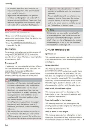 86
86 87
87 88
88 89
89 90
90 91
91 92
92 93
93 94
94 95
95 96
96 97
97 98
98 99
99 100
100 101
101 102
102 103
103 104
104 105
105 106
106 107
107 108
108 109
109 110
110 111
111 112
112 113
113 114
114 115
115 116
116 117
117 118
118 119
119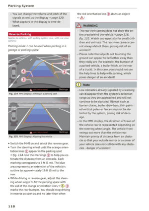 120
120 121
121 122
122 123
123 124
124 125
125 126
126 127
127 128
128 129
129 130
130 131
131 132
132 133
133 134
134 135
135 136
136 137
137 138
138 139
139 140
140 141
141 142
142 143
143 144
144 145
145 146
146 147
147 148
148 149
149 150
150 151
151 152
152 153
153 154
154 155
155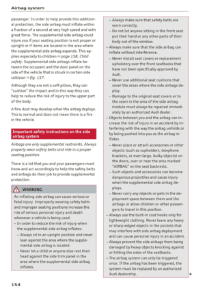 156
156 157
157 158
158 159
159 160
160 161
161 162
162 163
163 164
164 165
165 166
166 167
167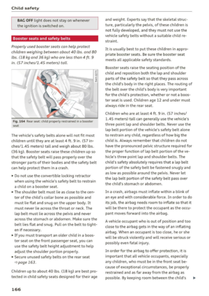 168
168 169
169 170
170 171
171 172
172 173
173 174
174 175
175 176
176 177
177 178
178 179
179 180
180 181
181 182
182 183
183 184
184 185
185 186
186 187
187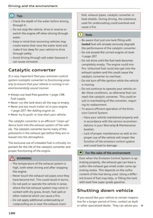 188
188 189
189 190
190 191
191 192
192 193
193 194
194 195
195 196
196 197
197 198
198 199
199 200
200 201
201 202
202 203
203 204
204 205
205 206
206 207
207 208
208 209
209 210
210 211
211 212
212 213
213 214
214 215
215 216
216 217
217 218
218 219
219 220
220 221
221 222
222 223
223 224
224 225
225 226
226 227
227 228
228 229
229 230
230 231
231 232
232 233
233 234
234 235
235 236
236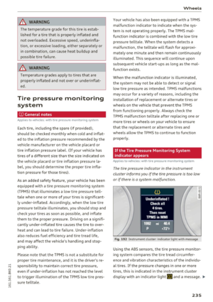 237
237 238
238 239
239 240
240 241
241 242
242 243
243 244
244 245
245 246
246 247
247 248
248 249
249 250
250 251
251 252
252 253
253 254
254 255
255 256
256 257
257 258
258 259
259 260
260 261
261 262
262 263
263 264
264 265
265 266
266 267
267 268
268 269
269 270
270 271
271 272
272 273
273 274
274 275
275 276
276 277
277