Page 33 of 112

NOTICE
ECA10022
Do not continue to operate the en-gine if it is overheating.
Oil change indicator “Oil”
Th")
INSTRUMENT AND CONTROL FUNCTIONS
4-6
1
2
345
6
7
8
9
10
11
12
gine cool. (See page 7-37.)
NOTICE
ECA10022
Do not continue to operate the en-gine if it is overheating.
Oil change indicator “Oil”
This indicator flashes at the initial 1000
km (600 mi), then at 5000 km (3000 mi)
and every 5000 km (3000 mi) thereafter
to indicate that the engine oil should be
changed.
After changing the engine oil, reset the
oil change indicator. To reset the oil
change indicator, select it by pushing
the “SELECT” button until “Oil Trip” is
displayed, and then push the “SE-
LECT” button at least one second.
When pushing the “SELECT” button,
“Oil Trip” starts flashing. While “Oil Trip”
is flashing, push the “SELECT” button
again for at least three seconds.
If the engine oil is changed before the
oil change indicator “Oil” flashes (i.e.
before the periodic oil change interval
has been reached), the indicator “Oil”
must be reset after the oil change for
the next periodic oil change to be indi-
cated at the correct time.
The electrical circuit of the indicator can
be checked according to the following
procedure.
1. Set the engine stop switch to “ ” and turn the power of the vehicle
on.
2. Check that the oil change indicator comes on for a few seconds and
then goes off.
3. If the oil change indicator does not come on, have a Yamaha dealer
check the electrical circuit.
V-belt replacement indicator
“V-Belt”
This indicator flashes every 20000 km
(12500 mi) when the V-belt needs to be
replaced.
After changing the V-belt, reset the
V-belt replacement indicator. To reset
the V-belt replacement indicator, select
it by pushing the “SELECT” button until
“V-Belt Trip” is displayed, and then
push the “SELECT” button at least one1. Oil change indicator “Oil”1
1. V-belt replacement indicator “V-Belt”1
2PW-9-E0_1.book 6 ページ 2015年2月19日 木曜日 午後3時30分
Page 34 of 112

INSTRUMENT AND CONTROL FUNCTIONS
4-7
1
2
34
5
6
7
8
9
10
11
12 second. When pushing the “SELECT”
button, “V-Belt Trip” starts flashing.
While “V-Belt Trip” is flashing, push the
“SELECT” button for at least three sec-
onds.
If the V-belt is changed before the
V-belt replacement indicator “V-Belt”
flashes (i.e. before the periodic V-belt
change interval has been reached), the
indicator “V-Belt” must be reset after
the V-belt change for the next periodic
V-belt change to be indicated at the
correct time.
The electrical circuit of the indicator can
be checked according to the following
procedure.
1. Turn the vehicle on and make sure that the engine stop switch is set to
“”.
2. Check that the V-belt replacement indicator comes on for a few sec-
onds and then goes off.
3. If the V-belt replacement indicator does not come on, have a Yamaha
dealer check the el ectrical circuit.Ambient temperature display, aver-
age fuel consumption, and instan-
taneous fuel consumption modes
Push the “RESET” button to switch the
display between the ambient tempera-
ture display “Air”, the average fuel con-
sumption mode “AVE_ _._ km/L” or
“AVE_ _._ L/100 km”, and the instanta-
neous fuel consumption mode “km/L”
or “L/100 km” in the following order:
Air
AVE_ _._ km/L or AVE_ _._ L/
100 km km/L or L/100 km Air
For the UK only:
Push the “RESET” button to switch the display between the ambient tempera-
ture display “Air”, the average fuel con-
sumption mode “AVE_ _._ MPG” and
the instantaneous fuel consumption
mode “MPG” in the following order:
Air
AVE_ _._ MPG MPG Air
Ambient temperature display
This display shows the ambient tem-
perature from –9 C to 40 C in 1 C in-
crements.
For the UK only:
15 F to 104 F in 1 F increments.
The temperature displayed may vary
from the ambient temperature. Pushing
1. Ambient temperature/average fuel consumption/instantaneous fuel
consumption
1
1. Ambient temperature display1
2PW-9-E0_1.book 7 ページ 2015年2月19日 木曜日 午後3時30分
Page 35 of 112

INSTRUMENT AND CONTROL FUNCTIONS
4-8
1
2
345
6
7
8
9
10
11
12
the “RESET” button switches the ambi-
ent temperature display to the average
fuel consumption and instantaneous
fuel consumption modes.
Average fuel consumption mode
The average fuel consumption display
can be set to either “AVE_ _._ km/L” or
“AVE_ _._ L/100 km” (except for the
UK).
For the UK only:
The average fuel consumption is dis-
played “AVE_ _._ MPG”.
This display shows the average fuel
consumption since it was last reset.
When the display is set to “AVE_
_._ km/L”, the average distance
that can be traveled on 1.0 L of fuel
is shown.
When the display is set to “AVE_
_._ L/100 km”, the average
amount of fuel necessary to travel
100 km is shown.
For the UK only: When the display
is set to “AVE_ _._ MPG”, the av-
erage distance that can be trav-
eled on 1.0 Imp.gal of fuel is
shown.
To reset the average fuel consumption
display, select it by pushing the “RE-
SET” button, and then push the “RE-
SET” button for at least one second.
TIPAfter resetting an average fuel con-
sumption display, “_ _._” is shown for
that display until the vehicle has trav-eled 1 km (0.6 mi). Instantaneous fuel consumption mode
The instantaneous fuel consumption
display can be set to either “km/L” or “L/
100 km” (except for the UK).
For the UK only:
The instantaneous fuel consumption is
displayed “MPG”.
When the display is set to “km/L”,
the distance that can be traveled
on 1.0 L of fuel under the current
riding conditions is shown.
When the display is set to “L/100
km”, the amount of fuel necessary
to travel 100 km under the current
riding conditions is shown.
1. Average fuel consumption display
1
1. Instantaneous fuel consumption display
1
2PW-9-E0_1.book 8 ページ 2015年2月19日 木曜日 午後3時30分
Page 36 of 112

INSTRUMENT AND CONTROL FUNCTIONS
4-9
1
2
34
5
6
7
8
9
10
11
12
For the UK only: The distance that
can be traveled on 1.0 Imp.gal of
fuel under the current riding condi-
tions is shown.
To switch between the instantaneous
fuel consumption displays, push the
“RESET” button for one second when
one of the displays is shown (except for
the UK).
TIPIf traveling at speeds under 10 km/h (6mi/h), “_ _._” is displayed.
Self-diagnosis device
This model is equipped with a self-diag-
nosis device for various electrical cir- cuits.
If a problem is detected in any of those
circuits, the engine
trouble warning light
comes on and the display indicates an
error code.
If the display indicates any error codes,
note the code number, and then have a
Yamaha dealer check the vehicle.
NOTICE
ECA11591
If the display indicates an error
code, the vehicle should be checked
as soon as possible in order to avoidengine damage.
EAU1234H
Handlebar switchesLeft
1. Error code display
1
1. Pass switch “PASS”
2. Dimmer switch “ / ”
3. Turn signal switch “ / ”
4. Horn switch “ ”
1
2
3
4
2PW-9-E0_1.book 9 ページ 2015年2月19日 木曜日 午後3時30分
Page 37 of 112

INSTRUMENT AND CONTROL FUNCTIONS
4-10
1
2
345
6
7
8
9
10
11
12
Right
EAU12361
Pass switch “PASS”
Press this switch to flash the headlight.
EAU12401
Dimmer switch “ / ”
Set this switch to “ ” for the high
beam and to “ ” for the low beam.
EAU12461
Turn signal switch “ / ”
To signal a right-hand turn, push this
switch to “ ”. To signal a left-hand
turn, push this switch to “ ”. When re-
leased, the switch returns to the center position. To cancel the turn signal
lights, push the switch in after it has re-
turned to the center position.
EAU12501
Horn switch “ ”
Press this switch to sound the horn.
EAU12661
Engine stop switch “ / ”
Set this switch to “ ” before starting
the engine. Set this switch to “ ” to
stop the engine in case of an emergen-
cy, such as when the vehicle overturns
or when the throttle cable is stuck.
EAU63631
“ON/ ” switch
With the smart key turned on and within
range, press this switch to turn on the
power to the vehicle. Then with the sid-
estand up and while applying the front
or rear brake, push this switch to crank
the engine with the starter. See page
6-1 for starting instructions prior to
starting the engine.
EAU63571
The engine trouble warning light andABS warning light (ABS model only)
may come on when the vehicle power
is on and the “ON/ ” switch is pushed,
but this does not indicate a malfunction.
EAU63580
Hazard switch “ ”
With the vehicle power is on, or when
the smart key system is in parking
mode, use this switch to turn on the
hazard lights (simultaneous flashing of
all turn signal lights).
The hazard lights are used in case of
an emergency or to warn other drivers
when your vehicle is stopped where it
might be a traffic hazard.NOTICE
ECA10062
Do not use the hazard lights for an
extended length of time with the en-
gine not running, otherwise the bat-tery may discharge.
1. Engine stop switch “ / ”
2. Hazard switch “ ”
3. “ON/ ” switch
1
2
3
2PW-9-E0_1.book 10 ページ 2015年2月19日 木曜日 午後3時30分
Page 38 of 112

INSTRUMENT AND CONTROL FUNCTIONS
4-11
1
2
34
5
6
7
8
9
10
11
12
EAU44912
Front brake leverThe front brake lever is located on the
right side of the handlebar. To apply the
front brake, pull this lever toward the
throttle grip.
The front brake lever is equipped with a
position adjusting dial. To adjust the
distance between the front brake lever
and the throttle grip, turn the adjusting
dial while holding the front brake lever
pushed away from the throttle grip.
Make sure that the appropriate setting
on the adjusting dial is aligned with the “ ” mark on the front brake lever.
EAU44922
Rear brake leverThe rear brake lever is located at the
left handlebar grip. To apply the rear
brake, pull this lever toward the handle-
bar grip.
The rear brake lever is equipped with a
position adjusting dial. To adjust the
distance between the rear brake lever
and the handlebar grip, turn the adjust-
ing dial while holding the rear brake le-
ver pushed away from the handlebar
grip. Make sure that the appropriate
setting on the adjusting dial is aligned
1. Front brake lever
2. Brake lever position adjusting dial
3. “ ” mark
4. Distance between brake lever and
handlebar grip
1
4
2
3
1. Rear brake lever
2. Brake lever position adjusting dial
3. “ ” mark
4. Distance between brake lever and
handlebar grip
54321
32
1
4
2PW-9-E0_1.book 11 ページ 2015年2月19日 木曜日 午後3時30分
Page 39 of 112
INSTRUMENT AND CONTROL FUNCTIONS
4-12
1
2
345
6
7
8
9
10
11
12
with the “ ” mark on the rear brake le-
ver.
EAU63230
Rear brake lock leverThis vehicle is equipped with a rear
brake lock lever to prevent the rear
wheel from moving while stopped at
traffic signals, railroad crossings, etc.
To lock the rear wheel
Push the rear brake lock lever to the left
until it snaps into place.
To unlock the rear wheel
Push the rear brake lock lever back to
the original position.TIPBe sure to check that the rear wheel
does not move when the rear brake
lock lever is applied.
WARNING
EWA12362
Never move the rear brake lock lever
to the left while the vehicle is mov-
ing, otherwise loss of control or an
accident may result. Make sure that
the vehicle is stopped before mov-
ing the rear brake lock lever to theleft.
1. Rear brake lock lever
1
2PW-9-E0_1.book 12 ページ 2015年2月19日 木曜日 午後3時30分
Page 40 of 112
The Yamaha ABS (Anti-lock Brake
System) features a dual electronic con-
trol system, which acts on the fron")
INSTRUMENT AND CONTROL FUNCTIONS
4-13
1
2
34
5
6
7
8
9
10
11
12
EAU63591
ABS (for ABS models)The Yamaha ABS (Anti-lock Brake
System) features a dual electronic con-
trol system, which acts on the front and
rear brakes independently.
Operate the brakes with ABS as you
would conventional brakes. If the ABS
is activated, a pulsating sensation may
be felt at the brake levers. In this situa-
tion, continue to apply the brakes and
let the ABS work; do not “pump” the
brakes as this will reduce braking effec-
tiveness.
WARNING
EWA16051
Always keep a sufficient distance
from the vehicle ahead to match the
riding speed even with ABS.
The ABS performs best with
long braking distances.
On certain surfaces, such as
rough or gravel roads, the brak-
ing distance may be longer withthe ABS than without.
The ABS is monitored by an ECU,
which will revert the system to conven-
tional braking if a malfunction occurs.
TIP
The ABS performs a self-diagno-
sis test each time the vehicle is
turned on and travels at a speed of
10 km/h (6 mi/h) or higher. During
this test, a clicking noise can be
heard and if either brake lever is
even slightly applied, a vibration
can be felt at the lever, but this
does not indicate a malfunction.
This ABS has a test mode which
allows the owner to experience the
pulsation at the brake levers when
the ABS is operating. However,
special tools are required, so
please consult your Yamaha deal-er.
NOTICE
ECA20100
Be careful not to damage the wheel
sensor or wheel sensor rotor; other-
wise, improper performance of theABS will result.
1. Front wheel sensor rotor
2. Front wheel sensor
1. Rear wheel sensor rotor
2. Rear wheel sensor
12
1
2
2PW-9-E0_1.book 13 ページ 2015年2月19日 木曜日 午後3時30分
 1
1 2
2 3
3 4
4 5
5 6
6 7
7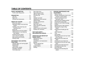 8
8 9
9 10
10 11
11 12
12 13
13 14
14 15
15 16
16 17
17 18
18 19
19 20
20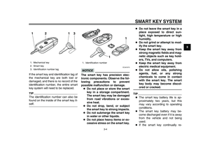 21
21 22
22 23
23 24
24 25
25 26
26 27
27 28
28 29
29 30
30 31
31 32
32 33
33 34
34 35
35 36
36 37
37 38
38 39
39 40
40 41
41 42
42 43
43 44
44 45
45 46
46 47
47 48
48 49
49 50
50 51
51 52
52 53
53 54
54 55
55 56
56 57
57 58
58 59
59 60
60 61
61 62
62 63
63 64
64 65
65 66
66 67
67 68
68 69
69 70
70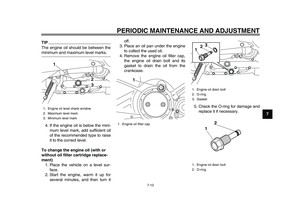 71
71 72
72 73
73 74
74 75
75 76
76 77
77 78
78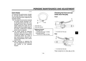 79
79 80
80 81
81 82
82 83
83 84
84 85
85 86
86 87
87 88
88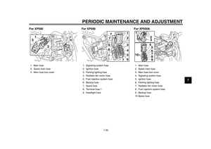 89
89 90
90 91
91 92
92 93
93 94
94 95
95 96
96 97
97 98
98 99
99 100
100 101
101 102
102 103
103 104
104 105
105 106
106 107
107 108
108 109
109 110
110 111
111