Page 25 of 112

SMART KEY SYSTEM
3-8
1
234
5
6
7
8
9
10
11
12
to the left or right and then press
the “ON/ ” switch.
If the steering continues to be
locked and will not release, the
smart key system indicator light
will flash 16 times and the steering
lock release operation will stop
midway. Move the handlebar gen-
tly to the left and right to help re-
lease the steering lock and thenpress the “ON/ ” switch again.
NOTICE
ECA15825
If the steering lock will not release
and the smart key system indicator
light is flashing, have a Yamahadealer check the smart key system.
3. The power of the vehicle is turned on once the steering lock is com-
pletely released. The smart key
system indicator light will go off
and the multi-function meter dis-
play will come on.
4. The engine can now be started. (See page 6-1.)
EAU61693
Powering off the vehicleTo turn the vehicle power off (and stop
the engine if it is running), with the
smart key on and within operating
range, press the “OFF/LOCK” switch.
Upon authentification of the smart key,
the beeper will sound once to confirm
that the vehicle power has been suc-
cessfully turned off.
If the smart key is not within operating
range or cannot communicate with the
vehicle when you press the “OFF/
LOCK” switch, the vehicle will not be
turned off and the beeper will sound for
three seconds (the smart key system
indicator light will also flash) to alert you
that the power was not successfully turned off. Confirm the location and
condition of the smart key and try pow-
ering off the vehicle again.
TIP
The rider must turn off the power of
the vehicle manually.
The power of the vehicle will not
turn off automatically even if the
smart key is moved out of operat-
ing range of the smart key system.
The power of the vehicle cannot be
turned off via the “OFF/LOCK”
switch when the vehicle is moving.
Be sure to stop the vehicle in a
safe place when turning off the
power.
Without the smart key, the vehicle
power can be turned off by press-
ing the “OFF/LOCK” switch again
while the smart key system indica-
tor light is flashing.
See page 7-38 for more informa-
tion about emergency mode and
how to turn the vehicle power onwithout the smart key.
1. “OFF/LOCK” switch
1
2PW-9-E0_1.book 8 ページ 2015年2月19日 木曜日 午後3時30分
Page 26 of 112

SMART KEY SYSTEM
3-9
1
23
4
5
6
7
8
9
10
11
12
EAU61612
How to lock the steeringAfter moving the vehicle to a safe park-
ing place, turn off the power of the vehi-
cle. Turn the handlebars fully to the left
and then press the “OFF/LOCK” switch
for at least one second.TIP
If the steering lock function locks
correctly, the beeper will sound
once.
If the steering lock function does
not lock correctly, the beeper will
sound for three seconds and the
smart key system indicator light
will flash. Turn the handlebar fully
to the left one more time and press
the “OFF/LOCK” switch again for
one second.WARNING
EWA14742
Do not operate the steering lockwhile the vehicle is moving.
EAU61683
Seat opening and closingTo open the seat 1. Place the vehicle on the center- stand.
2. With the smart key on and in oper- ating range, press the “SEAT
OPEN/ ” switch.
3. The seat lock will release upon au- thentication of the smart key.
4. Fold the seat up.1. “SEAT OPEN/ ” switch
1
2PW-9-E0_1.book 9 ページ 2015年2月19日 木曜日 午後3時30分
Page 27 of 112

SMART KEY SYSTEM
3-10
1
234
5
6
7
8
9
10
11
12
WARNING
EWA17941
Do not operate the “SEAT OPEN/ ”switch while the vehicle is moving.
To close the seat
Fold the seat down, and then push it
down to lock it in place.TIP
Make sure the seat is properly
closed before starting off.
In case of an emergency, the seat
can be opened with a mechanicalkey. (See page 7-38.)
EAU61593
Parking modeThe steering is locked, and the hazard
lights and turn signal lights can be
turned on, but all other electrical sys-
tems are off.
To enter parking mode 1. Lock the steering. (See page 3-9. )
2. Press and hold the “SEAT OPEN/ ” switch for at least one second.
3. Upon authentification of the smart key, the beeper will sound twice
and the smart key system will
change to parking mode and the
smart key system indicator light
will come on.TIPThe seat cannot be opened while inparking mode.NOTICE
ECA21990
Do not use the hazard lights for an
extended length of time, otherwisethe battery may discharge. To exit parking mode
Press and hold the “SEAT OPEN/ ”
switch. Upon authentication of the
smart key, the beeper will sound once
and parking mode is cancelled and the
smart key system indicator light will go
off.
2PW-9-E0_1.book 10 ページ 2015年2月19日 木曜日 午後3時30分
Page 28 of 112

4-1
1
2
34
5
6
7
8
9
10
11
12
INSTRUMENT AND CONTROL FUNCTIONS
EAU49397
Indicator ligh ts and warning
lights
EAU64080
Turn signal indicator lights “ ” and
“”
The corresponding indicator light flash-
es when the turn signal switch is
pushed to the left or right.TIPBoth indicator lights will flash when thehazard switch is used. (See page 4-10.)
EAU11081
High beam indicator light “ ”
This indicator light comes on when the
high beam of the headlight is switched
on.
EAU63521
Engine trouble warning light “ ”
This warning light comes on if an elec-
trical circuit monitoring the engine is not
working correctly. If this occurs, have a
Yamaha dealer check the self-diagno-
sis system.
The electrical circuit of the warning light
can be checked by turning the vehicle
power on. The warning light should
come on for a few seconds, and then
go off.
If the warning light does not come on
initially when the vehicle power is
turned on, or if the warning light re-
mains on, have a Yamaha dealer check
the electrical circuit.TIPThis warning light will come on when
the vehicle power is on and the “ON/ ”
switch is pushed, but this does not indi-cate a malfunction.
EAU63532
ABS warning light “ ” (for ABS
models)
In normal operation, the ABS warning
light comes on when the vehicle power
is turned on and goes off after traveling
at a speed of 10 km/h (6 mi/h) or higher.
If the ABS warning light:
does not come on when the vehi-
cle power is turned on
comes on or flashes while riding
does not go off after traveling at a
speed of 10 km/h (6 mi/h) or higher
The ABS may not work correctly. If any
of the above occurs, have a Yamaha
dealer check the system as soon as
possible. (See page 4-13 for an expla-
nation of the ABS.)WARNING
EWA16041
If the ABS warning light does not go
off after traveling at a speed of 10
km/h (6 mi/h) or higher, or if the
warning light comes on or flashes
while riding, the brake system re-
verts to conventional braking. If ei-
ther of the above occurs, or if the
warning light does not come on at
all, use extra caution to avoid possi-
1. Turn signal indicator lights “ ” and “ ”
2. Anti-lock Brake System (ABS) warning light “ ” (for ABS models)
3. High beam indicator light “ ”
4. Engine trouble warning light “ ”
5. Smart key system indicator light “ ”
1
541
1
3 2
ABS
ABS
2PW-9-E0_1.book 1 ページ 2015年2月19日 木曜日 午後3時30分
Page 29 of 112

INSTRUMENT AND CONTROL FUNCTIONS
4-2
1
2
345
6
7
8
9
10
11
12
ble wheel lock during emergency
braking. Have a Yamaha dealer
check the brake system and electri-
cal circuits as soon as possible.TIP
If the start switch is pushed while
the engine is running, the ABS
warning light will come on, but this
is not a malfunction.
The ABS warning light may come
on when revving the engine with
the scooter on its centerstand, but
this does not indicate a malfunc-tion.
EAU61652
Smart key system indicator light
“”
This indicator light communicates the
status of the smart key system. When
the smart key system is operating nor-
mally, this indicator light will be off. If
there is an error in the smart key sys-
tem, the indicator light will flash. The in-
dicator light will also flash when
communication between the vehicle
and smart key takes place and when
certain smart key system operations are carried out. (See page 3-1.)
TIPWhen the start switch is pushed, the in-
dicator light will come on for about one
second and then go off. If the indicator
light does not come on or go off as nor-
mal, have a Yamaha dealer check thevehicle.
EAU63541
SpeedometerThe speedometer shows the riding
speed.
When the vehicle power is turned on,
the speedometer needle will sweep
once across the speed range and then
return to zero in order to test the electri-
cal circuit.1. Speedometer1
2PW-9-E0_1.book 2 ページ 2015年2月19日 木曜日 午後3時30分
Page 30 of 112

INSTRUMENT AND CONTROL FUNCTIONS
4-3
1
2
34
5
6
7
8
9
10
11
12
EAU63551
TachometerThe electric tachometer allows the rider
to monitor the engine speed and keep it
within the ideal power range.
When the vehicle power is turned on,
the tachometer needle will sweep once
across the r/min range and then return
to zero r/min in order to test the electri-
cal circuit.NOTICE
ECA10032
Do not operate the engine in the ta-
chometer red zone.Red zone: 8250 r/min and above
EAU63562
Multi-function display
WARNING
EWA12313
Be sure to stop the vehicle before
making any setting changes to the
multi-function display. Changing
settings while riding can distract the
operator and increase the risk of anaccident.
The multi-function display is equipped
with the following:
a fuel meter
a coolant temperature meter
1. Tachometer red zone
2. Tachometer
21
1. “SELECT” button
2. Fuel meter
3. Fuel level warning indicator “ ”
4. Odometer
5. Coolant temperature warning indicator “”
6. Coolant temperature meter
7. “RESET” button
23
4
56
11
7
1. Tripmeter/fuel reserve tripmeter
2. Ambient temperature/average fuel consumption/instantaneous fuel
consumption
1. Clock
211
2PW-9-E0_1.book 3 ページ 2015年2月19日 木曜日 午後3時30分
Page 31 of 112

a fuel reserve tripmeter (which")
INSTRUMENT AND CONTROL FUNCTIONS
4-4
1
2
345
6
7
8
9
10
11
12
an odometer
two tripmeters (which show the
distance traveled since they were
last set to zero)
a fuel reserve tripmeter (which
shows the distance traveled when
the remaining fuel in the fuel tank
reaches approximately 3.0 L (0.79
US gal, 0.66 Imp.gal))
a self-diagnosis device
a clock
an ambient temperature display
a fuel consumption display (aver-
age and instantaneous consump-
tion functions)
an oil change tripmeter (which
shows the distance traveled since
the last engine oil change)
a V-belt replacement tripmeter
(which shows the distance trav-
eled since the last V-belt replace-
ment)
TIP
Be sure to turn the vehicle power
on before using the “SELECT” and
“RESET” buttons.
When the vehicle power is turned
on, all of the display segments of the multi-function display will ap-
pear one after the other and then
disappear, in order to test the elec-
trical circuits.
Clock
To set the clock:
1. Push the “SELECT” and “RESET” buttons together for at least two
seconds.
2. When the hour digits start flashing, push the “RESET” button to set the
hours.
3. Push the “SELECT” button, and the minute digits will start flashing.
4. Push the “RESET” button to set the minutes.
5. Push the “SELECT” button and then release it to start the clock.
Odometer and tripmeter modes1. Clock
1
1. Odometer/tripmeters/fuel reserve tripmeter
1. Oil change tripmeter
1
1
2PW-9-E0_1.book 4 ページ 2015年2月19日 木曜日 午後3時30分
Page 32 of 112

INSTRUMENT AND CONTROL FUNCTIONS
4-5
1
2
34
5
6
7
8
9
10
11
12 Pushing the “SELECT” button switches
the display between the odometer
mode and the tripmeter modes in the
following order:
Odo
Trip 1 Trip 2 V-Belt Trip
Oil Trip Odo
When approximately 3.0 L (0.79 US
gal, 0.66 Imp.gal) of fuel remains in the
fuel tank, the display will automatically
change to the fuel reserve tripmeter
mode “Trip F” and start counting the
distance traveled from that point. In that
case, pushing the “SELECT” button
switches the display between the vari-
ous tripmeter and odometer modes in
the following order:
Odo Trip 1 Trip 2 Trip F V-Belt Trip
Oil Trip Odo
To reset a tripmeter, select it by push-
ing the left set button until “Trip F”, “Trip
1” or “Trip 2” is displayed. While “Trip
F”, “Trip 1” or “Trip 2” is displayed, push
the “SELECT” button for at least one
second. If you do not reset the fuel re-
serve tripmeter manually, it will reset it-
self automatically and the display will
return to the prior mode after refueling
and traveling 5 km (3 mi).
TIPThe display cannot be changed back to
“Trip F” after resetting the fuel reservetripmeter. Fuel meter
The fuel meter indicates the amount of
fuel in the fuel tank. The display seg-
ments of the fuel meter disappear to-
wards “E” (Empty) as the fuel level
decreases. When the fuel level reaches
the bottom segment near “E”, the fuel
level warning indicator, “F”, “E”, and the
bottom segment will flash. Refuel as
soon as possible.
Coolant temperature meter
The coolant temperature meter indi-
cates the temperature of the coolant.
The coolant temperature varies with
changes in the weather and engine
load. If the top segment, “H”, “C”, and
coolant temperature warning indicator
flash, stop the vehicle and let the en-
1. V-belt replacement tripmeter1
1. Fuel reserve tripmeter
1
2PW-9-E0_1.book 5 ページ 2015年2月19日 木曜日 午後3時30分
 1
1 2
2 3
3 4
4 5
5 6
6 7
7 8
8 9
9 10
10 11
11 12
12 13
13 14
14 15
15 16
16 17
17 18
18 19
19 20
20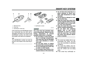 21
21 22
22 23
23 24
24 25
25 26
26 27
27 28
28 29
29 30
30 31
31 32
32 33
33 34
34 35
35 36
36 37
37 38
38 39
39 40
40 41
41 42
42 43
43 44
44 45
45 46
46 47
47 48
48 49
49 50
50 51
51 52
52 53
53 54
54 55
55 56
56 57
57 58
58 59
59 60
60 61
61 62
62 63
63 64
64 65
65 66
66 67
67 68
68 69
69 70
70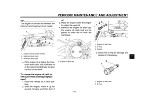 71
71 72
72 73
73 74
74 75
75 76
76 77
77 78
78 79
79 80
80 81
81 82
82 83
83 84
84 85
85 86
86 87
87 88
88 89
89 90
90 91
91 92
92 93
93 94
94 95
95 96
96 97
97 98
98 99
99 100
100 101
101 102
102 103
103 104
104 105
105 106
106 107
107 108
108 109
109 110
110 111
111