Page 49 of 112

INSTRUMENT AND CONTROL FUNCTIONS
4-22
1
2
345
6
7
8
9
10
11
12
EAU46023
Shock absorber assembly
WARNING
EWA10222
This shock absorber assembly con-
tains highly pressurized nitrogen
gas. Read and understand the fol-
lowing information before handling
the shock absorber assembly.
Do not tamper with or attempt to
open the cylinder assembly.
Do not subject the shock ab-
sorber assembly to an open
flame or other high heat source.
This may cause the unit to ex-
plode due to excessive gas
pressure.
Do not deform or damage the
cylinder in any way. Cylinder
damage will result in poor
damping performance.
Do not dispose of a damaged or
worn-out shock absorber as-
sembly yourself. Take the shock
absorber assembly to a Yamahadealer for any service.
EAU15306
SidestandThe sidestand is located on the left side
of the frame. Raise the sidestand or
lower it with your foot while holding the
vehicle upright.TIPThe built-in sidestand switch is part of
the ignition circuit cut-off system, which
cuts the ignition in certain situations.
(See the following section for an expla-
nation of the ignition circuit cut-off sys-tem.)
WARNING
EWA10242
The vehicle must not be ridden with
the sidestand down, or if the sides-
tand cannot be properly moved up
(or does not stay up), otherwise the
sidestand could contact the ground
and distract the operator, resulting
in a possible loss of control.
Yamaha’s ignition circuit cut-off
system has been designed to assist
the operator in fulfilling the respon-
sibility of raising the sidestand be-
fore starting off. Therefore, check
this system regularly and have a Yamaha dealer repair it if it does not
function properly.
2PW-9-E0_1.book 22 ページ 2015年2月19日 木曜日 午後3時30分
Page 50 of 112
INSTRUMENT AND CONTROL FUNCTIONS
4-23
1
2
34
5
6
7
8
9
10
11
12
EAU63612
Ignition circuit cut-off systemThe ignition circuit cut-off system (com-
prising the sidestand switch and brake
light switches) has the following func-
tions.
It prevents starting when the side-
stand is up, but neither brake is ap-
plied.
It prevents starting when either
brake is applied, but the sidestand
is still down.
It cuts the running engine when the
sidestand is moved down.
Periodically check the operation of the
ignition circuit cut-off system according
to the following procedure.
2PW-9-E0_1.book 23 ページ 2015年2月19日 木曜日 午後3時30分
Page 51 of 112

INSTRUMENT AND CONTROL FUNCTIONS
4-24
1
2
345
6
7
8
9
10
11
12
With the engine turned off:
1. Move the sidestand down.
2. Make sure that the engine stop switch is turned on.
3. Turn the vehicle power on.
4. Keep the front or rear brake applied.
5. Push the “ON/ ” switch.
Does the engine start?
With the engine still off:
6. Move the sidestand up.
7. Keep the front or rear brake applied.
8. Push the “ON/ ” switch.
Does the engine start?
With the engine still running:
9. Move the sidestand down.
Does the engine stall?
The system is OK. The scooter can be ridden. The sidestand switch may not be working correctly.
The scooter should not be ridden until
checked by a Yamaha dealer.
The sidestand switch may not be working correctly.
The scooter should not be ridden until
checked by a Yamaha dealer.
YES NO YES NO NO YES
The brake switch may not be working correctly.
The scooter should not be ridden until
checked by a Yamaha dealer.The vehicle must be placed on the center-
stand during this inspection. If a malfunction is noted, have a Yamaha
dealer check the system before riding.
WARNING
2PW-9-E0_1.book 24 ページ 2015年2月19日 木曜日 午後3時30分
Page 52 of 112
INSTRUMENT AND CONTROL FUNCTIONS
4-25
1
2
34
5
6
7
8
9
10
11
12
EAU63800
Auxiliary DC connector
WARNING
EWA12532
To prevent electrical shock or
short-circuiting, make sure that the
cap is installed when the auxiliaryDC connector is not being used.NOTICE
ECA20090
The accessory connected to the
auxiliary DC connector should not
be used with the engine turned off,
and the load must never exceed 24
W (2 A), otherwise the fuse may blowor the battery may discharge. This vehicle is equipped with an auxilia-
ry DC connector. A 12–V accessory
connected to the auxiliary DC connec-
tor can be used when the vehicle power
is on.1. Auxiliary DC connector cap
1
1. Auxiliary DC connector
1
2PW-9-E0_1.book 25 ページ 2015年2月19日 木曜日 午後3時30分
Page 53 of 112

5-1
1
2
3
456
7
8
9
10
11
12
FOR YOUR SAFETY – PRE-OPERATION CHECKS
EAU15598
Inspect your vehicle each time you use it to make sure the vehicle is in safe operating condition. Always follow the inspection
and maintenance procedures and schedules described in the Owner’s Manual.
WARNING
EWA11152
Failure to inspect or maintain the vehicle properly increases the possibility of an accident or equipment damage.
Do not operate the vehicle if you find any problem. If a problem cannot be corrected by the procedures provided inthis manual, have the vehicle inspected by a Yamaha dealer.
Before using this vehicle, check the following points:
ITEM CHECKS PAGE
Fuel Check fuel level in fuel tank.
Refuel if necessary.
Check fuel line for leakage.
Check fuel tank breather hose and overflow hose for obstructions, cracks or
damage, and check hose connections. 4-15
Engine oil Check oil level in engine.
If necessary, add recommended oil to specified level.
Check vehicle for oil leakage. 7-11
Coolant Check coolant level in reservoir.
If necessary, add recommended coolant to specified level.
Check cooling system for leakage. 7-14
Front brake Check operation.
If soft or spongy, have Yamaha dealer bleed hydraulic system.
Check brake pads for wear.
Replace if necessary.
Check fluid level in reservoir.
If necessary, add specified brake fluid to specified level.
Check hydraulic system for leakage. 7-20, 7-22, 7-23
2PW-9-E0_1.book 1 ページ 2015年2月19日 木曜日 午後3時30分
Page 54 of 112

FOR YOUR SAFETY – PRE-OPERATION CHECKS
5-2
1
2
3
45
6
7
8
9
10
11
12
Rear brake Check operation.
If soft or spongy, have Yamaha dealer bleed hydraulic system.
Check brake pads for wear.
Replace if necessary.
Check fluid level in reservoir.
If necessary, add specified brake fluid to specified level.
Check hydraulic system for leakage. 7-20, 7-22, 7-23
Throttle grip Make sure that operation is smooth.
Check throttle grip free play.
If necessary, have Yamaha dealer adjust throttle grip free play and lubricate cable
and grip housing. 7-17, 7-25
Wheels and tires Check for damage.
Check tire condition and tread depth.
Check air pressure.
Correct if necessary. 7-18, 7-20
Brake levers Make sure that operation is smooth.
Lubricate lever pivoting points if necessary. 7-25
Centerstand, sidestand Make sure that operation is smooth.
Lubricate pivots if necessary. 7-26
Chassis fasteners Make sure that all nuts, bolts
and screws are properly tightened.
Tighten if necessary. —
Instruments, lights, signals
and switches Check operation.
Correct if necessary.
—
Sidestand switch Check operation of ignition circuit cut-off system.
If system is not working correctly, have Yamaha dealer check vehicle. 4-22
ITEM CHECKS PAGE
2PW-9-E0_1.book 2 ページ 2015年2月19日 木曜日 午後3時30分
Page 55 of 112

6-1
1
2
3
4
567
8
9
10
11
12
OPERATION AND IMPORT ANT RIDING POINTS
EAU15952
Read the Owner’s Manual carefully to
become familiar with all controls. If
there is a control or function you do not
understand, ask your Yamaha dealer.
WARNING
EWA10272
Failure to familiarize yourself with
the controls can lead to loss of con-
trol, which could cause an accidentor injury.
EAU63621
TIPThis model is equipped with:
a lean angle sensor to stop the en-
gine in case of a turnover. In this
case, the display will indicate error
code 30, but this is not a malfunc-
tion. Turn the vehicle power off
and then on to clear the error code.
Failing to do so will prevent the en-
gine from starting even though the
engine will crank when pushing the
start switch.
an engine auto-stop system. The
engine stops automatically if left
idling for 20 minutes. If the engine
stops, simply push the start switchto restart the engine.
EAU61552
Starting the engineNOTICE
ECA10251
See page 6-4 for engine break-in in-
structions prior to operating the ve-hicle for the first time.
In order for the ignition circuit cut-off
system to enable starting, the sides-
tand must be up. (See page 4-23.)
1. With the smart key turned on, ap- proach the vehicle.
2. Push the “ON/ ” switch.
Upon authentication of the smart
key, the beeper will sound twice,
the smart key system indicator
light will come on momentarily and1. “ON/ ” switch
1
2PW-9-E0_1.book 1 ページ 2015年2月19日 木曜日 午後3時30分
Page 56 of 112
 will be
released. The engine trouble
warning light should come on for a
few seconds and then go off.")
OPERATION AND IMPORTANT RIDING POINTS
6-2
1
2
3
4
56
7
8
9
10
11
12 the steering lock (if applied) will be
released. The engine trouble
warning light should come on for a
few seconds and then go off.
For ABS models:
The ABS warning light should
come on when the power of the ve-
hicle is turned on, and go off once
the vehicle reaches a traveling
speed of 10 km/h (6 mi/h) or high-
er.
NOTICE
ECA21980
If the engine warning light or the
ABS warning light (for
ABS-equipped models) does not
come on and then go off as ex-
plained above, see page 4-1 for thewarning light circuit check.
3. Close the throttle completely.
4. Start the engine by pushing the “ON/ ” switch while applying the
front or rear brake.
If the engine does not start within 5
seconds of pressing the “ON/ ”
switch, wait 10 seconds before
pressing the switch again to allow the battery voltage to restore.
NOTICE
ECA11043
For maximum engine life, never ac-
celerate hard when the engine iscold!
EAU45093
Starting off1. While pulling the rear brake lever
with your left hand and holding the
grab bar with your right hand, push
the scooter off the centerstand.
2. Sit astride the seat, and then ad- just the rear view mirrors.
3. Switch the turn signals on.
4. Check for oncoming traffic, and then slowly turn the throttle grip (on
the right) in order to take off.
5. Switch the turn signals off.1. Grab bar
1
2PW-9-E0_1.book 2 ページ 2015年2月19日 木曜日 午後3時30分
 1
1 2
2 3
3 4
4 5
5 6
6 7
7 8
8 9
9 10
10 11
11 12
12 13
13 14
14 15
15 16
16 17
17 18
18 19
19 20
20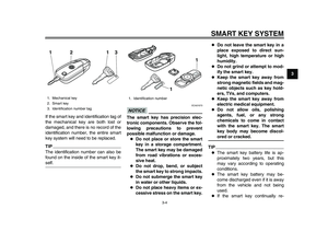 21
21 22
22 23
23 24
24 25
25 26
26 27
27 28
28 29
29 30
30 31
31 32
32 33
33 34
34 35
35 36
36 37
37 38
38 39
39 40
40 41
41 42
42 43
43 44
44 45
45 46
46 47
47 48
48 49
49 50
50 51
51 52
52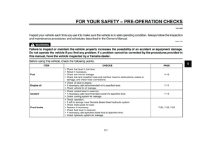 53
53 54
54 55
55 56
56 57
57 58
58 59
59 60
60 61
61 62
62 63
63 64
64 65
65 66
66 67
67 68
68 69
69 70
70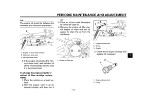 71
71 72
72 73
73 74
74 75
75 76
76 77
77 78
78 79
79 80
80 81
81 82
82 83
83 84
84 85
85 86
86 87
87 88
88 89
89 90
90 91
91 92
92 93
93 94
94 95
95 96
96 97
97 98
98 99
99 100
100 101
101 102
102 103
103 104
104 105
105 106
106 107
107 108
108 109
109 110
110 111
111")
