Page 73 of 112
, do not
mix any chemical a")
PERIODIC MAINTENANCE AND ADJUSTMENT
7-14
1
2
3
4
5
678
9
10
11
12
NOTICE
ECA11621
In order to prevent clutch slip-
page (since the engine oil also
lubricates the clutch), do not
mix any chemical additives. Do
not use oils with a diesel speci-
fication of “CD” or oils of a high-
er quality than specified. In
addition, do not use oils labeled
“ENERGY CONSERVING II” or
higher.
Make sure that no foreign mate-rial enters the crankcase.
11. Start the engine, and then let it idle for several minutes while checking
it for oil leakage. If oil is leaking, im-
mediately turn the engine off and
check for the cause.
12. Turn the engine off, and then check the oil level and correct it if
necessary.
13. Reset the oil change indicator. (See page 4-6.)
TIPIf the engine oil is changed before the
oil change indicator comes on (i.e. be-
fore the periodic oil change interval has been reached), the indicator must be
reset after the oil change for the next
periodic oil change to be indicated at
the correct time.
EAU20071
CoolantThe coolant level should be checked
before each ride. In addition, the cool-
ant must be changed at the intervals
specified in the periodic maintenance
and lubrication chart.
EAU52023
To check the coolant level
1. Place the vehicle on the center- stand.TIP
The coolant level must be checked
on a cold engine since the level
varies with engine temperature.
Make sure that the vehicle is posi-
tioned straight up when checking
the coolant level. A slight tilt to theside can result in a false reading.
2. Check the coolant level through the check window.
TIPThe coolant should be between theminimum and maximum level marks.
2PW-9-E0_1.book 14 ページ 2015年2月19日 木曜日 午後3時30分
Page 74 of 112

PERIODIC MAINTENANCE AND ADJUSTMENT
7-15
1
2
3
4
5
67
8
9
10
11
12 3. If the coolant is at or below the
minimum level mark, remove the
left floorboard mat by pulling it up.
4. Remove the coolant reservoir cov- er by removing the screw.
5. Open the coolant reservoir cap, add coolant to the maximum level
mark, and then close the reservoir
cap. WARNING! Remove only
the coolant reservoir cap. Never
attempt to remove the radiator
cap when the engine is
hot.
[EWA15162]
NOTICE: If coolant is
not available, use distilled water
or soft tap water instead. Do not
use hard water or salt water
since it is harmful to the engine.
If water has been used instead
of coolant, replace it with cool-
ant as soon as possible, other- wise the cooling system will not
be protected against frost and
corrosion. If water has been
added to the coolant, have a
Yamaha dealer check the anti-
freeze content of the coolant as
soon as possible, otherwise the
effectiveness of the coolant will
be reduced.
[ECA10473]
6. Install the coolant reservoir cover
by installing the screw.
7. Place the left floorboard mat in the original position and push it down-
ward to secure it.
1. Coolant level check window
2. Maximum level mark
3. Minimum level mark
1. Floorboard mat
1
2
3
1
1. Coolant reservoir cover
2. Screw
1 2
1. Coolant reservoir capCoolant reservoir capacity (up to the
maximum level mark):
0.27 L (0.29 US qt, 0.24 Imp.qt)
1
2PW-9-E0_1.book 15 ページ 2015年2月19日 木曜日 午後3時30分
Page 75 of 112

PERIODIC MAINTENANCE AND ADJUSTMENT
7-16
1
2
3
4
5
678
9
10
11
12
EAU52031
Replacing the air filter elementThe air filter element should be re-
placed at the intervals specified in the
periodic maintenance and lubrication
chart. Replace the air filter element
more frequently if you are riding in un-
usually wet or dusty areas.
To replace the air filter element 1. Remove panel C. (See page 7-8.)
2. Remove the air filter case cover by removing the screws.
3. Pull the air filter element out. 4. Insert a new air filter element into
the air filter case. NOTICE: Make
sure that the air filter element is
properly seated in the air filter
case. The engine should never
be operated without the air filter
element installed, otherwise the
piston(s) and/or cylinder(s) may
become excessively worn.
[ECA10482]
5. Install the air filter case cover by in- stalling the screws.
6. Install the panel.
EAU33483
Adjusting the engine idling
speedThe engine idling speed must be
checked and, if necessary, adjusted as
follows at the intervals specified in the
periodic maintenance and lubrication
chart.
The engine should be warm before
making this adjustment. 1. Remove panel D. (See page 7-8.)
2. Check the engine idling speed and, if necessary, adjust it to spec-
ification by turning the idle adjust-
ing screw. To increase the engine
idling speed, turn the screw in di-
rection (a). To decrease the en-
gine idling speed, turn the screw in
direction (b).
1. Screw
2. Air filter case cover
1
1 2
1. Air filter element
1
2PW-9-E0_1.book 16 ページ 2015年2月19日 木曜日 午後3時30分
Page 76 of 112
PERIODIC MAINTENANCE AND ADJUSTMENT
7-17
1
2
3
4
5
67
8
9
10
11
12
TIPIf the specified idling speed cannot be
obtained as described above, have aYamaha dealer make the adjustment. 3. Install the panel.
EAU21385
Checking the thrott le grip free
playThe throttle grip free play should mea-
sure 3.0–5.0 mm (0.12–0.20 in) at the
inner edge of the throttle grip. Periodi-
cally check the throttle grip free play
and, if necessary, have a Yamaha
dealer adjust it.
EAU21402
Valve clearanceThe valve clearance changes with use,
resulting in improper air-fuel mixture
and/or engine noise. To prevent this
from occurring, the valve clearance
must be adjusted by a Yamaha dealer
at the intervals specified in the periodic
maintenance and lubrication chart.
1. Idle adjusting screwEngine idling speed: 1100–1300 r/min
1(a)(b)
1. Throttle grip free play
1
2PW-9-E0_1.book 17 ページ 2015年2月19日 木曜日 午後3時30分
Page 77 of 112

PERIODIC MAINTENANCE AND ADJUSTMENT
7-18
1
2
3
4
5
678
9
10
11
12
EAU51973
TiresTires are the only contact between the
vehicle and the road. Safety in all con-
ditions of riding depends on a relatively
small area of road contact. Therefore, it
is essential to maintain the tires in good
condition at all times and replace them
at the appropriate time with the speci-
fied tires.
Tire air pressure
The tire air pressure should be checked
and, if necessary, adjusted before each
ride.
WARNING
EWA10504
Operation of this vehicle with im-
proper tire pressure may cause se-
vere injury or death from loss of
control.
The tire air pressure must be
checked and adjusted on cold
tires (i.e., when the temperature
of the tires equals the ambient
temperature).
The tire air pressure must be ad-
justed in accordance with the
riding speed and with the total weight of rider, passenger, car-
go, and accessories approved
for this model.WARNING
EWA10512
Never overload your vehicle. Opera-
tion of an overloaded vehicle couldcause an accident.
Tire inspection
The tires must be checked before each
ride. If the center tread depth reaches
the specified limit, if the tire has a nail or
glass fragments in it, or if the sidewall is
cracked, have a Yamaha dealer re-
place the tire immediately.
TIPThe tire tread depth limits may differ
from country to country. Always complywith the local regulations.
Tire air pressure (measured on cold
tires):
0–90 kg (0–198 lb):Front: 225 kPa (2.25 kgf/cm
2, 33 psi)
Rear: 250 kPa (2.50 kgf/cm2, 36 psi)
XP500 90–196 kg (198–432 lb)
XP500A 90–193 kg (198–425 lb):
Front: 225 kPa (2.25 kgf/cm2, 33 psi)
Rear: 280 kPa (2.80 kgf/cm2, 41 psi)
Maximum load*:
XP500 196 kg (432 lb)
XP500A 193 kg (425 lb)
* Total weight of rider, passenger, car-
go and accessories
1. Tire sidewall
2. Tire tread depthMinimum tire tread depth (front and
rear): 1.6 mm (0.06 in)
1 2
2PW-9-E0_1.book 18 ページ 2015年2月19日 木曜日 午後3時30分
Page 78 of 112

PERIODIC MAINTENANCE AND ADJUSTMENT
7-19
1
2
3
4
5
67
8
9
10
11
12
WARNING
EWA10472
Have a Yamaha dealer replace
excessively worn tires. Besides
being illegal, operating the vehi-
cle with excessively worn tires
decreases riding stability and
can lead to loss of control.
The replacement of all wheel
and brake-related parts, includ-
ing the tires, should be left to a
Yamaha dealer, who has the
necessary professional knowl-
edge and experience to do so.
Ride at moderate speeds after
changing a tire since the tire
surface must first be “broken
in” for it to develop its optimalcharacteristics.
Tire information
This model is equipped with tubeless
tires and tire air valves.
Tires age, even if they have not been
used or have only been used occasion-
ally. Cracking of the tread and sidewall
rubber, sometimes accompanied by
carcass deformation, is an evidence of ageing. Old and aged tires shall be
checked by tire specialists to ascertain
their suitability for further use.
WARNING
EWA16101
The front and rear tires should
be of the same make and de-
sign, otherwise the handling
characteristics of the vehicle
may be different, which could
lead to an accident.
Always make sure that the valve
caps are securely installed to
prevent air pressure leakage.
Use only the tire valves and
valve cores listed below toavoid tire deflation during a ride.
After extensive tests, only the tires list-
ed below have been approved for this
model by Yamaha.
Front tire: Size:120/70R15 M/C 56H
Manufacturer/model:
DUNLOP/GPR-100F
Tire air valve: PVR59A
Valve core: #9100 (original)
Rear tire:
Size:160/60R15 M/C 67H
Manufacturer/model:
DUNLOP/GPR-100
Tire air valve: TR412
Valve core: #9100 (original)
2PW-9-E0_1.book 19 ページ 2015年2月19日 木曜日 午後3時30分
Page 79 of 112

PERIODIC MAINTENANCE AND ADJUSTMENT
7-20
1
2
3
4
5
678
9
10
11
12
EAU51921
Cast wheelsTo maximize the performance, durabil-
ity, and safe operation of your vehicle,
note the following points regarding the
specified wheels.
The wheel rims should be checked
for cracks, bends, warpage or oth-
er damage before each ride. If any
damage is found, have a Yamaha
dealer replace the wheel. Do not
attempt even the smallest repair to
the wheel. A deformed or cracked
wheel must be replaced.
The wheel should be balanced
whenever either the tire or wheel
has been changed or replaced. An
unbalanced wheel can result in
poor performance, adverse han-
dling characteristics, and a short-
ened tire life.
After repairing or replacing the
front tire, tighten the valve stem nut
and locknut to the specified
torques.
EAU50861
Checking the front and rear
brake lever free playFront
Rear
There should be no free play at the
1. Valve stem nut
2. Valve stem locknutTightening torques: Valve stem nut:2.0 Nm (0.2 m·kgf, 1.4 ft·lbf)
Valve stem locknut:
3.0 Nm (0.3 m·kgf, 2.2 ft·lbf)
1
2
1. No brake lever free play
1. No brake lever free play
1
1
2PW-9-E0_1.book 20 ページ 2015年2月19日 木曜日 午後3時30分
Page 80 of 112

PERIODIC MAINTENANCE AND ADJUSTMENT
7-21
1
2
3
4
5
67
8
9
10
11
12 brake lever ends. If there is free play,
have a Yamaha dealer inspect the
brake system.
WARNING
EWA14212
A soft or spongy feeling in the brake
lever can indicate the presence of air
in the hydraulic system. If there is air
in the hydraulic system, have a
Yamaha dealer bleed the system be-
fore operating the vehicle. Air in the
hydraulic system will diminish the
braking performance, which may re-
sult in loss of control and an acci-dent.
EAU53032
Adjusting the rear brake lock
cableRear brake lock cable adjustment may
be required if the rear brake lock lever
does not hold properly. When the rear
brake lock lever is not in use, the rear
brake lock cable length should mea-
sure 43–45 mm (1.69–1.77 in) at the
rear brake caliper.
Periodically check the rear brake lock
cable length and, if necessary, adjust it
as follows.
To increase the rear brake lock cable
length, turn the adjusting nut at the rear
brake caliper in direction (a). To de- crease the rear brake lock cable length,
turn the adjusting nut in direction (b).
WARNING! If proper adjustment
cannot be obtained as described,
have a Yamaha dealer make this ad-
justment.
[EWA16151]
Check that the rear brake lock is re-
leased, and then make sure that the
rear wheel could rotate smoothly.
1. Adjusting nut
2. Rear brake lock cable length
2
1
(a)
(b)
2PW-9-E0_1.book 21 ページ 2015年2月19日 木曜日 午後3時30分
 1
1 2
2 3
3 4
4 5
5 6
6 7
7 8
8 9
9 10
10 11
11 12
12 13
13 14
14 15
15 16
16 17
17 18
18 19
19 20
20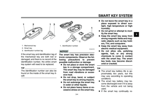 21
21 22
22 23
23 24
24 25
25 26
26 27
27 28
28 29
29 30
30 31
31 32
32 33
33 34
34 35
35 36
36 37
37 38
38 39
39 40
40 41
41 42
42 43
43 44
44 45
45 46
46 47
47 48
48 49
49 50
50 51
51 52
52 53
53 54
54 55
55 56
56 57
57 58
58 59
59 60
60 61
61 62
62 63
63 64
64 65
65 66
66 67
67 68
68 69
69 70
70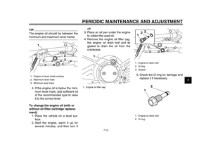 71
71 72
72 73
73 74
74 75
75 76
76 77
77 78
78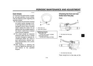 79
79 80
80 81
81 82
82 83
83 84
84 85
85 86
86 87
87 88
88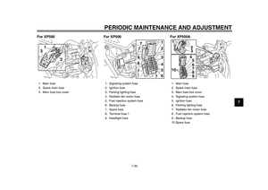 89
89 90
90 91
91 92
92 93
93 94
94 95
95 96
96 97
97 98
98 99
99 100
100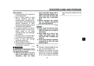 101
101 102
102 103
103 104
104 105
105 106
106 107
107 108
108 109
109 110
110 111
111