Page 385 of 434

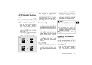
For cold and snowy weather 9-28 Vehicle care and maintenance
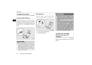
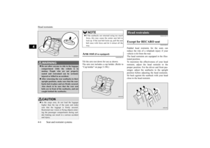
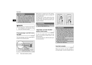
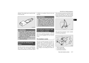
9
Have a competent mechanic inspect the com- plete exhaust system and nearby body areas for broken, damaged, deteriorated, or mispo- sitioned parts if you notice any of the follow-ing: A change in the sound of the exhaust sys- tem The smell of exhaust fumes inside the vehicle The underside or rear of the vehicle is damaged
Also check the exhaust system each time the vehicle is raised for lubrication, oil changes,or required service. Any open seams or loose connections could let dangerous exhaust fumes seep into the luggage compartment andpassenger compartments. Check for holes or exhaust gas leaks caused by corrosion or damage. Check the joints and connections for looseness or exhaust gas leaks. Check the rubber hangers and brackets for damage.
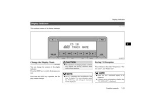
N00942500114
The hood lock release mechanism and hoodsafety catch should be checked, cleaned, and oiled when needed for easy movement and to stop rust and wear. Use Multipurpose GreaseNLGI Grade 2 sparingly for all sliding parts of the hood latch and release lever. Work the grease into the hood lock mechanism until allthe movable surfaces are covered.Also, put a light coat of the same grease on the safety catch wherever moving parts touch.
N00942600102
The ventilation slots in front of the wind-shield should be brushed clear after a heavy snowfall so that the operation of the heatingand ventilation systems will not be impaired. To prevent freezing of the weatherstripping on the doors, engine hood, etc., they should be treated with silicone grease.
It is a good idea to carry a shovel or a short- handled spade in the vehicle during the win- ter so that you can clear away snow if you getstranded. A small hand-brush for sweeping snow off the vehicle and a plastic scraper for the windshield, side and rear window are alsouseful.
N00942700259
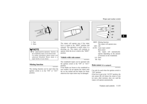
The fusible links will melt
to prevent a fire if
a large current attempts to flow through cer-tain electrical systems. In case of a melted fusible link, see your authorized Mitsubishi Motors dealer or arepair facility of your choice for inspection and replacement. For the fusible links, please refer to “Fuseload capacities” on page 9-30.
Check for any of the following conditions:
Hood lock release mechanism and safety catch For cold and snowy weather Ventilation slots Weatherstripping
Additional equipment (For regions where snow is encoun- tered) Fusible links
WA R N I N G Fusible links must not be replaced by any other device. Failing to fit the correct fus- ible link may result in fire in the vehicle,property destruction and serious or fatal injuries at any time.
BK0210300US.bo
ok 28 ページ 2014年4月8日 火曜日 午前10時46分
Page 386 of 434

Fuses
Vehicle care and maintenance 9-29
9
N00942800801
To prevent damage to the electrical system from short-circuiting or overloading, eachindividual circuit is equipped with a fuse. The fuse blocks are located in the passenger com- partment and in the engine compartment. The fuse blocks in the passenger compart- ment are located behind the fuse lid on the driver’s side as shown.
1. Open the fuse lid and pull to remove it. 2. For vehicles with the bottom cover, use the puller to loosen the 2 clips (A) and push down the bottom cover. The puller is in the fuse block in the engine compart-ment. Refer to “Fuse replacement” on page 9-33.
3. To put back the fuse lid, line up the fuse lid hook (B) with the clamp (C) on theinstrument panel and push the lid back in.
Fuses Fuse block location Passenger compartment A- Main fuse blockB- Sub fuse block
WA R N I N G When changing fuses, do not damage the driver’s knee airbag harness or acciden- tally strike the airbag area with hard objects. Improper work methods could result in an accidental driver’s knee air-bag deployment or could make the driver’s knee airbag inoperable. Either of these situations could result in seriousinjury or death.NOTE
When finished, be sure to return the puller to the fuse block in the engine compartment.
BK0210300US.bo
ok 29 ページ 2014年4月8日 火曜日 午前10時46分
Page 387 of 434

Fuses 9-30 Vehicle care and maintenance
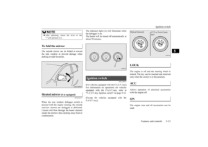
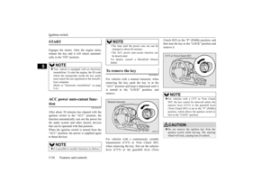
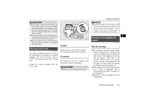
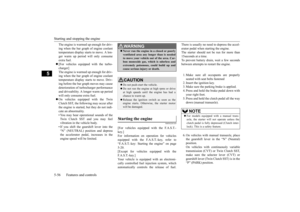
9
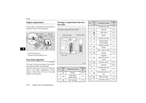
In the engine compartment, the fuse block is located as shown in the illustration. 1. Push the lock lever. 2. Remove the fuse block cover.
N00954800231
This fuse list shows the names of the electri- cal systems and their fuse capacities. There are spare fuses in the cover of the fuseblock in the engine compartment. Always replace a blown fuse with one of the same capacity as the original. Engine compartment Fuse load capacities
Passenger compartment fuse loca- tion table No.
Sym- bol
Electrical system
Capac-ity
1 Heater 30 A
*
2
Stop lights (Brake lights)
15 A
3 Rear fog light 10 A
Main fuse block
Sub fuse block
Passenger compartme
nt fuse location
4 Windshield wiper 30 A 5 Optional 10 A 6 Door locks 20 A 7Radio15 A8 Control unit relay 7.5 A 9
Interior lights (Dome lights)
15 A
10
Hazard warning
flasher
15 A
11 Rear window wiper 15 A 12 Gauges 7.5 A 13
Cigarette
lighter/Accessory
socket
15 A
14 Ignition switch 10 A 15 Sunroof 20 A 16
Outside rearview
mirrors
10 A
17
All-wheel drive sys-
tem
10 A
18 Back-up lights 7.5 A 19 Accessory socket 15 ANo.
Sym- bol
Electrical system
Capac-ity
BK0210300US.bo
ok 30 ページ 2014年4月8日 火曜日 午前10時46分
Page 388 of 434

Fuses
Vehicle care and maintenance 9-31
9
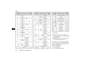
* - Fusible link Some fuses may not be installed on your vehicle, depending on the vehicle model or specifications. The table above shows the main equip- ment corresponding to each fuse. 20
Power window con-
trol
30 A
*
21 Defogger 30 A
*
22
Heated
outside rearview
mirrors
7.5 A
23 115V Power outlet 15 A 24 Power seats
25 (20) A
25 Heated seats 30 ANo.
Sym- bol
Electrical system
Capac-ity
Engine compartment fuse location table * - Front of the vehicle
No.
Sym- bol
Electrical system
Capac-ity
1 Front fog lights 15 A 2 Engine 7.5 AEngine compartment fuse location
*
Behind the fuse block cover
*
3 Automatic transaxle 20 A 4 Horn 10 A 5 Alternator 7.5 A 6 Headlight washer 20 A 7 Air conditioning 10 A 8
/
ETV/Oil cooler fan (Twin Clutch SST)
Except for vehi- cles with turbo- charger
15 A
ETV
Vehicles with tur-bocharger
9 Security horn 20 A 10 Wiper deicer 15 A 11 — — — 13
Daytime running
lights
10 A
14
Headlight
(high beam) (left)
10 A
15
Headlight
(high beam) (right)
10 A
No.
Sym- bol
Electrical system
Capac-ity
BK0210300US.bo
ok 31 ページ 2014年4月8日 火曜日 午前10時46分
Page 389 of 434

Fuses 9-32 Vehicle care and maintenance
9
* - Fusible link Some fuses may not be installed on your vehicle, depending on the vehicle modelor specifications. The table above shows the main equip- ment corresponding to each fuse.
There are no 7.5 A, 25 A or 30 A spare fuses. If a fuse of one of these capacities blows,replace it temporarily by borrowing one of the fuses indicated below. 7.5 A: 10 A spare fuse25 A: 20 A spare fuse 30 A: 30 A audio amplifier fuse
16
Head- light (low/high beam) (left)
Dis- charge
20 A
17
Head- light (low/high beam) (right)
Dis- charge
20 A
18
Headlight (low beam) (left)
Halogen 10 A
19
Headlight (low beam) (right)
Halogen 10 A
20
ENG/ POWER
Except for vehi- cles with turbo- charger
10 A
I/C SPRAY
Vehicles with tur-bocharger
21 Ignition coil 10 ANo.
Sym- bol
Electrical system
Capac-ity
22
ENG/ POWER
Vehicles with tur-bocharger
20 A
ENG/ POWER
Except for vehi- cles with turbo- charger
20 A
Fuel line heater
25 A
23
Fuel pump
Except for vehi-cles with turbo- charger
15 A
Vehicles with tur- bocharger
20 A
24 Starter 30 A
*
25
Va l v e l i f t control
Except for vehi- cles with turbo- charger
40 A
*
——
Vehicles with tur-bocharger
—
26
Anti-lock braking
system
40 A
*
No.
Sym- bol
Electrical system
Capac-ity
27
Anti-lock braking
system
30 A
*
28
Air conditioning con- denser fan motor
30 A
*
29 Radiator fan motor 40 A
*
30 IOD IOD 30 A31 Audio amplifier 30 A 32 Diesel 30 A 33 — Spare fuse 10 A 34 — Spare fuse 15 A35 — Spare fuse 20 ANo.
Sym- bol
Electrical system
Capac-ity
BK0210300US.bo
ok 32 ページ 2014年4月8日 火曜日 午前10時46分
Page 390 of 434

Fuses
Vehicle care and maintenance 9-33
9
Replace the borrowed fuse with a fuse that has the correct capacity as soon as possible.
N00954900027
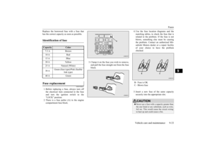
1. Before replacing a fuse, always turn offthe electrical item connected to the fuseand turn the ignition switch to the“LOCK” position. 2. There is a fuse puller (A) in the engine compartment fuse block.
3. Clamp it on the fuse you wish to remove, and pull the fuse straight out from the fuse block.
4. Use the fuse location diagrams and the matching tables, to check the fuse that is related to the problem. If the fuse is not blown, something else must be causingthe problem. Contact an authorized Mit- subishi Motors dealer or a repair facility of your choice to have the problemchecked. 5. Insert a new fuse of the same capacity securely into the appropriate slot.
Identification of fuse Capacity
Color
7.5 A Brown10 A Red15 A Blue20 A Yellow25 A Natural (White) 30 A
Green (fuse type)/Pink (fusible
link type)
40 A Green
Fuse replacement
B- Fuse is OK C- Blown fuseCAUTION Never use a fuse with a capacity greater than the one listed or any substitute, such as wire, foil etc. This would cause the circuit wiringto heat up and could cause a fire.
BK0210300US.bo
ok 33 ページ 2014年4月8日 火曜日 午前10時46分
Page 391 of 434

Replacement of light bulbs 9-34 Vehicle care and maintenance
9
N00942900219
Before replacing a bulb, be sure the light is off. Do not touch the glass part of the newbulb with your bare fi
ngers; the oil from your
skin will stay on the glass and dim or destroy the bulb when it gets hot.
N00943000099
The bulb should only be replaced with a newbulb with the same ra
ting and type. The type
and rating are listed on the base of the bulb.
N00950301932
[Except for vehicles with high intensity dis-charge headlights]
If the replacement fuse blows again after a short time, have the electrical system checked by an authorized Mitsubishi Motors dealer or a repair faci
lity of your choice to
find and correct the cause.
Replacement of light bulbs
CAUTION Bulbs are extremely hot immediately after being turned off. When replacing a bulb, wait for it to coolsufficiently before touching it. You could otherwise be burned.NOTE
If you are unsure of how to carry out the work as required, it is recommended that these procedures be carried out by an autho-rized Mitsubishi Motors dealer or a repair facility of your choice. Be careful not to scratch the vehicle body when removing a light and lens.CAUTION
When it rains, or when the vehicle has been washed, the inside of the lens sometimes becomes temporarily foggy. This is the same phenomenon as when window glass mists up on a humid day, and does not indicate a func-tional problem. When the light is switched on, the heat will remove the fog. However, if water gathersinside the light, please have it checked by an authorized Mitsubishi Motors dealer or a repair facility of your choice.
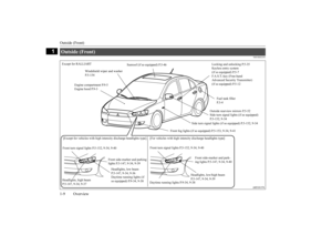
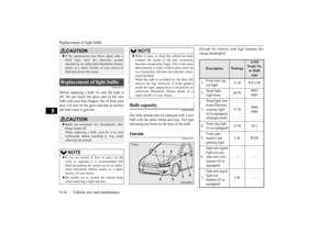
Bulb capacity Outside
NOTE
Front
Description
Wattage
ANSI Trade No. or Bulb type
1-
Front turn sig- nal light
21 W WY21W
2-
Head light, high beam
60 W
9005 HB3
3-
Head light, low beam/Daytime running light(if so equipped) (Halogen bulb)
51 W
9006 HB4
4-
Front fog light (if so equipped)
55 W H11
5-
Front side- marker and parking light
5 W W5W
6-
Side turn signal light (on out-side rear-view mirror) (If so equipped)
——
7-
Side turn signal light (on fender) (If so equipped)
5 W —
BK0210300US.bo
ok 34 ページ 2014年4月8日 火曜日 午前10時46分
Page 392 of 434
![MITSUBISHI LANCER 2015 8.G Owners Manual Replacement of light bulbs
Vehicle care and maintenance 9-35
9
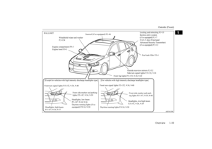
[For vehicles with high intensity discharge headlights]
Description
Wattage or Can-dle power
ANSI Trade No. or Bulb type
1-
Front MITSUBISHI LANCER 2015 8.G Owners Manual Replacement of light bulbs
Vehicle care and maintenance 9-35
9
[For vehicles with high intensity discharge headlights]
Description
Wattage or Can-dle power
ANSI Trade No. or Bulb type
1-
Front](/manual-img/19/7462/w960_7462-391.png)
Replacement of light bulbs
Vehicle care and maintenance 9-35
9
[For vehicles with high intensity discharge headlights]
Description
Wattage or Can-dle power
ANSI Trade No. or Bulb type
1-
Front turn sig- nal light
21 W WY21W
2-
Daytime run- ning light
27 W
1156
32 cp
3-
Head light, low/high beam (Discharge bulb)
35 W —
5-
Front side- marker and parking light
5 W WY5W
6-
Side turn signal light (on out-side rear-view mirror)
——
WA R N I N G Check with an authorized Mitsubishi Motors dealer or a repair facility of your choice when it is necessary to repair a dis- charge headlight or to replace the bulb. The power circuit, bulb and electrodesgenerate high voltages that may cause a severe electrical shock.NOTE
The side turn signal light (on outside rear- view mirror) uses LEDs rather than bulbs. For repair and replacement, contact an authorized Mitsubishi Motors dealer or arepair facility of your choice. It is not possible to re
pair or replace only the
bulb for the side turn signal light (on fender). Check with an authorized Mitsubishi Motors dealer or a repair facility of your choicewhen the light needs to be repaired or replaced.Rear
Description
Wattage
ANSI Trade No. or Bulb type
8-
High-mounted stop light
——
9-
License plate light
5 W W5W
10- Back-up light 21 W 7440 11- Tail light 5 W W5W 12-
Tail and stop light
21/5 W 7443
13-
Rear turn sig- nal light
21 W 7440
14-
Rear side- marker light
5 W W5W
NOTE
The high-mounted stop light uses LEDs rather than bulbs. For repair and replace- ment, contact an authorized MitsubishiMotors dealer or a repair facility of your choice.
BK0210300US.bo
ok 35 ページ 2014年4月8日 火曜日 午前10時46分