2015 MERCEDES-BENZ SLK-CLASS ROADSTER seats
[x] Cancel search: seatsPage 105 of 358
tion of the SmartKey in the ignition lock. This
makes it easier to exit the vehicle and rescue
the occupants.
The crash-responsive EASY-EXIT feature is
only operational if the EASY-EXIT/ENTRY fea- ture is activated in the on-board computer( Y page 207).
Mirrors
Rear-view mirror
X
Anti-glare mode: flick anti-glare lever :
forwards or back.
Exterior mirrors
Adjusting the exterior mirrors
GWARNING
You could lose control of your vehicle if you do the following while driving:
R adjust the driver's seat, head restraint,
steering wheel or mirrors
R fasten the seat belt
There is a risk of an accident.
Adjust the driver's seat, head restraint, steer-
ing wheel and mirror and fasten your seat belt before starting the engine.
GWARNING
The exterior mirror on the front-passenger
side reduces the size of the image. Visible
objects are actually closer than they appear.
This means that you could misjudge the dis-
tance from road users traveling behind, e.g.
when changing lane. There is a risk of an acci-
dent.
For this reason, always make sure of the
actual distance from the road users traveling
behind by glancing over your shoulder.
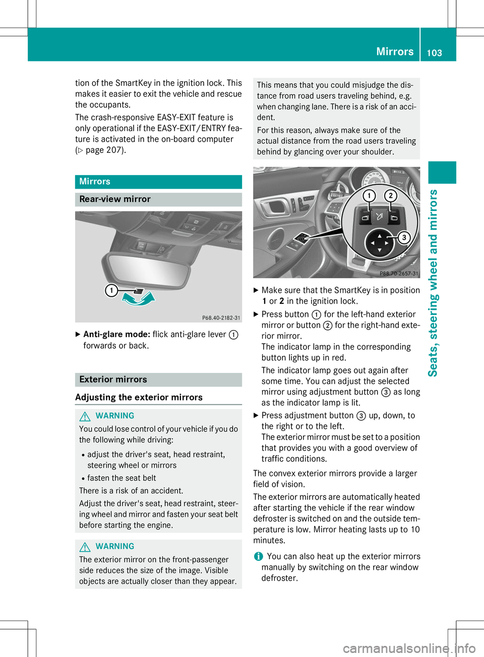
X Make sure that the SmartKey is in position
1 or 2in the ignition lock.
X Press button :for the left-hand exterior
mirror or button ;for the right-hand exte-
rior mirror.
The indicator lamp in the corresponding
button lights up in red.
The indicator lamp goes out again after
some time. You can adjust the selected
mirror using adjustment button =as long
as the indicator lamp is lit.
X Press adjustment button =up, down, to
the right or to the left.
The exterior mirror must be set to a position
that provides you with a good overview of
traffic conditions.
The convex exterior mirrors provide a larger
field of vision.
The exterior mirrors are automatically heated after starting the vehicle if the rear window
defroster is switched on and the outside tem-
perature is low. Mirror heating lasts up to 10 minutes.
iYou can also heat up the exterior mirrors
manually by switching on the rear window
defroster.
Mirrors103
Seats, steering wheel and mirrors
Z
Page 106 of 358
Folding the exterior mirrors in or out
electrically
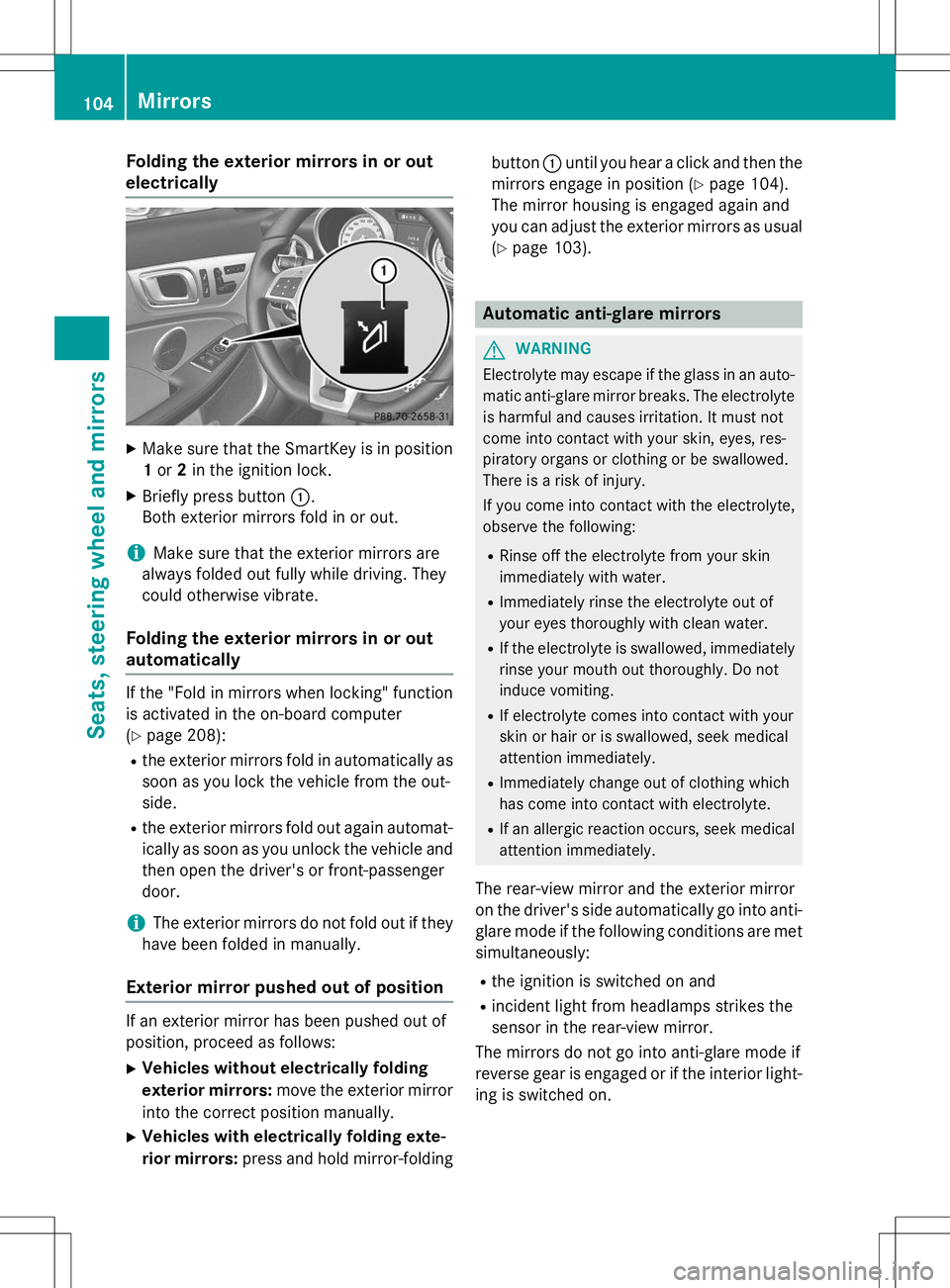
XMake sure that the SmartKey is in position
1 or 2in the ignition lock.
X Briefly press button :.
Both exterior mirrors fold in or out.
iMake sure that the exterior mirrors are
always folded out fully while driving. They
could otherwise vibrate.
Folding the exterior mirrors in or out
automatically
If the "Fold in mirrors when locking" function
is activated in the on-board computer( Y page 208):
R the exterior mirrors fold in automatically as
soon as you lock the vehicle from the out-
side.
R the exterior mirrors fold out again automat-
ically as soon as you unlock the vehicle and
then open the driver's or front-passenger
door.
iThe exterior mirrors do not fold out if they
have been folded in manually.
Exterior mirror pushed out of position
If an exterior mirror has been pushed out of
position, proceed as follows:
X Vehicles without electrically folding
exterior mirrors: move the exterior mirror
into the correct position manually.
X Vehicles with electrically folding exte-
rior mirrors: press and hold mirror-folding button
:until you hear a click and then the
mirrors engage in position ( Ypage 104).
The mirror housing is engaged again and
you can adjust the exterior mirrors as usual
( Y page 103).
Automatic anti-glare mirrors
GWARNING
Electrolyte may escape if the glass in an auto-
matic anti-glare mirror breaks. The electrolyte
is harmful and causes irritation. It must not
come into contact with your skin, eyes, res-
piratory organs or clothing or be swallowed.
There is a risk of injury.
If you come into contact with the electrolyte,
observe the following:
R Rinse off the electrolyte from your skin
immediately with water.
R Immediately rinse the electrolyte out of
your eyes thoroughly with clean water.
R If the electrolyte is swallowed, immediately
rinse your mouth out thoroughly. Do not
induce vomiting.
R If electrolyte comes into contact with your
skin or hair or is swallowed, seek medical
attention immediately.
R Immediately change out of clothing which
has come into contact with electrolyte.
R If an allergic reaction occurs, seek medical
attention immediately.
The rear-view mirror and the exterior mirror
on the driver's side automatically go into anti-
glare mode if the following conditions are met simultaneously: R the ignition is switched on and
R incident light from headlamps strikes the
sensor in the rear-view mirror.
The mirrors do not go into anti-glare mode if
reverse gear is engaged or if the interior light-
ing is switched on.
104Mirrors
Seats, steering wheel and mirrors
Page 107 of 358
Parking position for the exterior mir-
ror on the front-passenger side
Setting and storing the parking position
Using reverse gear
You can position the front-passenger side
exterior mirror in such a way that you can see
the rear wheel on that side as soon as you
engage reverse gear. You can store this posi-
tion.
X Make sure that the vehicle is stationary and
that the SmartKey is in position 2in the
ignition lock.
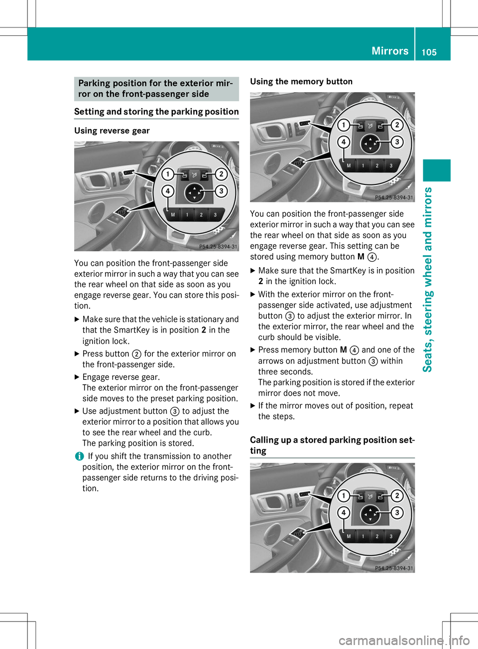
X Press button ;for the exterior mirror on
the front-passenger side.
X Engage reverse gear.
The exterior mirror on the front-passenger
side moves to the preset parking position.
X Use adjustment button =to adjust the
exterior mirror to a position that allows you to see the rear wheel and the curb.
The parking position is stored.
iIf you shift the transmission to another
position, the exterior mirror on the front-
passenger side returns to the driving posi-tion. Using the memory button
You can position the front-passenger side
exterior mirror in such a way that you can see
the rear wheel on that side as soon as you
engage reverse gear. This setting can be
stored using memory button M? .
X Make sure that the SmartKey is in position
2 in the ignition lock.
X With the exterior mirror on the front-
passenger side activated, use adjustmentbutton =to adjust the exterior mirror. In
the exterior mirror, the rear wheel and the
curb should be visible.
X Press memory button M? and one of the
arrows on adjustment button =within
three seconds.
The parking position is stored if the exterior
mirror does not move.
X If the mirror moves out of position, repeat
the steps.
Calling up a stored parking position set-
ting
Mirrors105
Seats, steering wheel and mirrors
Z
Page 108 of 358
XTurn the SmartKey to position 2in the igni-
tion lock.
X Adjust the exterior mirror on the front-
passenger side using button ;.
X Engage reverse gear.
The exterior mirror on the front-passenger
side moves to the stored parking position.
The exterior mirror on the front-passenger
side moves back to its original position:
R as soon as you exceed a speed of 9 mph
(15 km/h)
R if you press button :for the exterior mir-
ror on the driver's side
Memory function
Storing settings
GWARNING
If you use the memory function on the driver's side while driving, you could lose control of
the vehicle as a result of the adjustments
being made. There is a risk of an accident.
Only use the memory function on the driver's
side when the vehicle is stationary.
GWARNING
When the memory function adjusts the seat or steering wheel, you and other vehicle occu-
pants – particularly children – could become
trapped. There is a risk of injury.
While the memory function is making adjust-
ments, make sure that no one has any body
parts in the sweep of the seat or steering
wheel. If somebody becomes trapped, imme-
diately release the memory function position
button. The adjustment process is stopped.
GWARNING
Children could become trapped if they acti-
vate the memory function, particularly when
unattended. There is a risk of injury.
When leaving the vehicle, always take the
SmartKey with you and lock the vehicle. Never leave children unsupervised in the vehicle. The memory function can be used at any time,
e.g. even when the SmartKey isn't in the igni-
tion lock.
With the memory function, you can store up
to three different settings, e.g. for three dif-
ferent people.
The following settings are stored as a single
memory preset:
R position of the seat, backrest and head
restraint
R driver's side: steering wheel position
R driver's side: position of the exterior mir-
rors on the driver's and front-passengersides
XAdjust the seat electrically ( Ypage 98).
X On the driver's side, adjust the steering
wheel ( Ypage 101) and the exterior mirrors
( Y page 103).
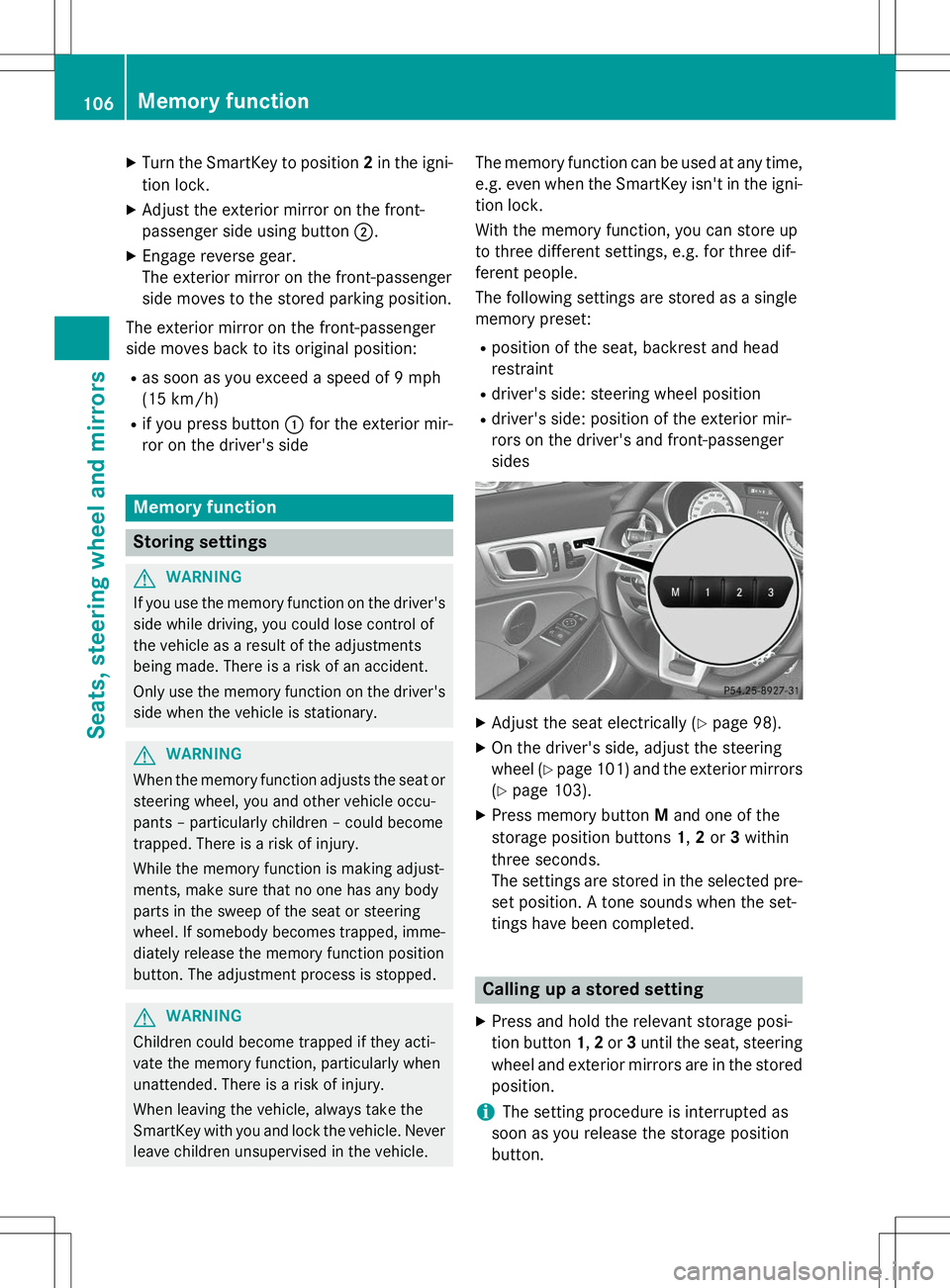
X Press memory button Mand one of the
storage position buttons 1,2 or 3within
three seconds.
The settings are stored in the selected pre- set position. A tone sounds when the set-
tings have been completed.
Calling up a stored setting
X Press and hold the relevant storage posi-
tion button 1,2 or 3until the seat, steering
wheel and exterior mirrors are in the stored position.
iThe setting procedure is interrupted as
soon as you release the storage position
button.
106Memory function
Seats, steering wheel and mirrors
Page 261 of 358
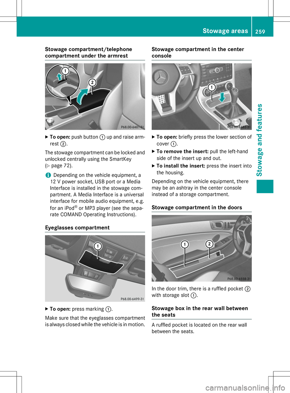
Stowage compartment/telephone
compartment under the armrest
XTo open: push button :up and raise arm-
rest ;.
The stowage compartment can be locked and
unlocked centrally using the SmartKey ( Y page 72).
iDepending on the vehicle equipment, a
12 V power socket, USB port or a Media
Interface is installed in the stowage com-
partment. A Media Interface is a universal
interface for mobile audio equipment, e.g.
for an iPod ®
or MP3 player (see the sepa-
rate COMAND Operating Instructions).
Eyeglasses compartment
X To open: press marking :.
Make sure that the eyeglasses compartment
is always closed while the vehicle is in motion.
Stowage compartment in the center
console
X To open: briefly press the lower section of
cover :.
X To remove the insert: pull the left-hand
side of the insert up and out.
X To install the insert: press the insert into
the housing.
Depending on the vehicle equipment, there
may be an ashtray in the center console
instead of a storage compartment.
Stowage compartment in the doors
In the door trim, there is a ruffled pocket ;
with storage slot :.
Stowage box in the rear wall between
the seats
A ruffled pocket is located on the rear wall
between the seats.
Stowage areas259
Stowage and features
Z
Page 302 of 358
GWARNING
Electrostatic build-up can lead to the creationof sparks, which could ignite the highly explo-
sive gases of a battery. There is a risk of an
explosion.
Before handling the battery, touch the vehicle body to remove any existing electrostatic
build-up.
The highly flammable gas mixture forms when
charging the battery as well as when jump-starting.
Always make sure that neither you nor the
battery is electrostatically charged. A build-
up of electrostatic charge can be caused, for
example:
R by wearing clothing made from synthetic
fibers
R due to friction between clothing and seats
R if you push or pull the battery across the
carpet or other synthetic materials
R if you wipe the battery with a cloth
GWARNING
During the charging process, a battery produ-
ces hydrogen gas. If a short circuit occurs or
sparks are created, the hydrogen gas can
ignite. There is a risk of an explosion.
R Make sure that the positive terminal of a
connected battery does not come into con-
tact with vehicle parts.
R Never place metal objects or tools on a bat-
tery.
R It is important that you observe the descri-
bed order of the battery terminals when
connecting and disconnecting a battery.
R When jump-starting, make sure that the
battery poles with identical polarity areconnected.
R It is particularly important to observe the
described order when connecting and dis-
connecting the jumper cables.
R Never connect or disconnect the battery
terminals while the engine is running.
GWARNING
Battery acid is caustic. There is a risk of injury.
Avoid contact with skin, eyes or clothing. Do
not inhale any battery gases. Do not lean over
the battery. Keep children away from batter-
ies. Wash away battery acid immediately with
plenty of clean water and seek medical atten- tion.
HEnvironmental note
Batteries contain dangerous
substances. It is against the
law to dispose of them with
the household rubbish. They
must be collected separately and recycled to protect theenvironment.
Dispose of batteries in an
environmentally friendly
manner. Take discharged
batteries to a qualified spe-
cialist workshop or a special
collection point for used bat-teries.
!Have the battery checked regularly at a
qualified specialist workshop.
Observe the service intervals in the Main-
tenance Booklet or contact a qualified spe-
cialist workshop for more information.
!You should have all work involving the
battery carried out at a qualified specialist
workshop. In the exceptional case that it is
necessary for you to disconnect the battery yourself, make sure that:
R you switch off the engine and remove the
key. On vehicles with KEYLESS-GO,
ensure that the ignition is switched off.
Check that all the indicator lamps in the
instrument cluster are off. Otherwise,
electronic components, such as the
alternator, may be damaged.
R you first remove the negative terminal
clamp and then the positive terminal
clamp. Never swap the terminal clamps.
300Battery (vehicle)
Roadside Assistance
Page 318 of 358
Follow recommended tire inflation pressures
and check the pressure of all the tires includ-
ing the spare wheel:R monthly, at least
R if the load changes
R before beginning a long journey
R under different operating conditions, e.g.
off-road driving
If necessary, correct the tire pressure.
iThe specifications on the sample Tire and
Loading Information placard and tire pres-
sure tables are examples. Tire pressure
specifications are vehicle-specific and may
deviate from the data shown here. The tire pressure specifications that are valid for
your vehicle can be found on the Tire and
Loading Information placard and tire pres-
sure table on the vehicle.
General notes
The recommended tire pressures for the tires
mounted at the factory can be found on the
labels described here.
Operation with the emergency spare
wheel (Y page 343).
Further information on tire pressures can be
obtained at a qualified specialist workshop.
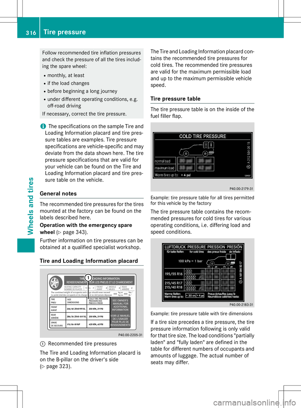
Tire and Loading Information placard
:Recommended tire pressures
The Tire and Loading Information placard is
on the B-pillar on the driver's side( Y page 323). The Tire and Loading Information placard con-
tains the recommended tire pressures for
cold tires. The recommended tire pressures
are valid for the maximum permissible load
and up to the maximum permissible vehicle
speed.
Tire pressure table
The tire pressure table is on the inside of the
fuel filler flap.
Example: tire pressure table for all tires permitted
for this vehicle by the factory
The tire pressure table contains the recom-
mended pressures for cold tires for various
operating conditions, i.e. differing load and
speed conditions.
Example: tire pressure table with tire dimensions
If a tire size precedes a tire pressure, the tire pressure information following is only valid
for that tire size. The load conditions "partially
laden" and "fully laden" are defined in the
table for different numbers of occupants and
amounts of luggage. The actual number of
seats may differ.
316Tire pressure
Wheels and tires
Page 326 of 358
The maximum gross axle weight rating isthe maximum weight that can be carried
by one axle (front or rear axle). Never
exceed the maximum load or the maxi-
mum gross axle weight rating for the
front or rear axle.
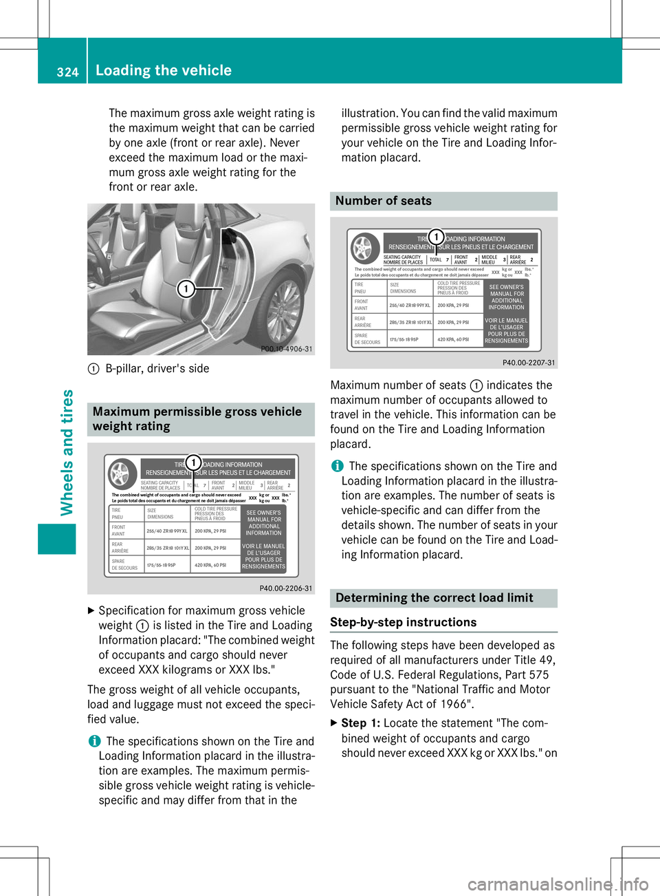
:B-pillar, driver's side
Maximum permissible gross vehicle
weight rating
X Specification for maximum gross vehicle weight :is listed in the Tire and Loading
Information placard: "The combined weight of occupants and cargo should never
exceed XXX kilograms or XXX lbs."
The gross weight of all vehicle occupants,
load and luggage must not exceed the speci-
fied value.
iThe specifications shown on the Tire and
Loading Information placard in the illustra-
tion are examples. The maximum permis-
sible gross vehicle weight rating is vehicle- specific and may differ from that in the illustration. You can find the valid maximum
permissible gross vehicle weight rating for
your vehicle on the Tire and Loading Infor-
mation placard.
Number of seats
Maximum number of seats :indicates the
maximum number of occupants allowed to
travel in the vehicle. This information can be
found on the Tire and Loading Informationplacard.
iThe specifications shown on the Tire and
Loading Information placard in the illustra-
tion are examples. The number of seats is
vehicle-specific and can differ from the
details shown. The number of seats in your vehicle can be found on the Tire and Load-
ing Information placard.
Determining the correct load limit
Step-by-step instructions
The following steps have been developed as
required of all manufacturers under Title 49,
Code of U.S. Federal Regulations, Part 575
pursuant to the "National Traffic and Motor
Vehicle Safety Act of 1966". X Step 1: Locate the statement "The com-
bined weight of occupants and cargo
should never exceed XXX kg or XXX lbs." on
324Loading the vehicle
Wheels and tires