2015 MERCEDES-BENZ S-CLASS COUPE transmission
[x] Cancel search: transmissionPage 374 of 417

X
Remove the towing eye from the vehicle
tool kit/stowage tray (Y page 357).
X Press the mark on cover :inwards in the
direction of the arrow.
X Remove cover :from the opening.
X Screw in the towing eye clockwise as far as
it will go and tighten it.
Removing the towing eye X
Loosen the towing eye and unscrew it.
X Attach cover :to the bumper and press
until it engages.
X Place the towing eye in the vehicle tool kit/
stowage tray. Towing the vehicle with both axles on
the ground
It is important that you observe the safety
instructions when towing away your vehicle
(Y page 369).
The automatic transmission automatically
shifts to position Pwhen you open the driver's
or front-passenger door or when you remove the key from the ignition lock.
In order to ensure that the automatic trans-
mission stays in position Nwhen towing the
vehicle, you must observe the following
points:
X You must use the key instead of the Start/
Stop button (Y page 161).
X Make sure that the vehicle is stationary and
that the key is in position 0in the ignition
lock.
X Turn the key to position 2in the ignition
lock.
X Depress and hold the brake pedal.
X Shift the automatic transmission to posi-
tion N.
X Release the brake pedal.
X Release the electric parking brake. X
Leave the key in position 2in the ignition
lock.
X Switch on the hazard warning lamps
(Y page 128).
i In order to signal a change of direction
when towing the vehicle with the hazard
warning lamps switched on, use the com-
bination switch as usual. In this case, only
the turn signals for the desired direction
flash. When you reset the combination
switch, the hazard warning lamps start
flashing again. Towing the vehicle away with the rear
axle raised
Only vehicles without 4MATIC can be
towed away with the rear axle raised.
! The ignition must be switched off if you
are towing the vehicle with the rear axle
raised. Intervention by ESP ®
could other-
wise damage the brake system.
! Vehicles with 4MATIC must not be towed
with the front or rear axle raised; otherwise,
the transmission may be damaged.
! Vehicles with automatic transmission
must not be towed with the rear axle raised.
The car/trailer combination may otherwise swerve or even overturn. Transporting the vehicle
! You may only secure the vehicle by the
wheels, not by parts of the vehicle such as
axle or steering components. Otherwise,
the vehicle could be damaged.
The towing eye can be used to pull the vehicle
onto a trailer or transporter for transporta-
tion.
X Turn the key to position 2in the ignition
lock.
X Shift the automatic transmission to posi-
tion N. Towing away and tow-starting
371Breakdown assistance Z
Page 375 of 417

As soon as the vehicle is loaded:
X Prevent the vehicle from rolling away by
applying the electric parking brake.
X Shift the automatic transmission to posi-
tion P.
X Turn the key to position 0in the ignition
lock and remove it.
X Secure the vehicle. Notes for 4MATIC vehicles
! Vehicles with 4MATIC must not be towed
with the front or rear axle raised; otherwise,
the transmission may be damaged.
Vehicles with 4MATIC may either be towed
away with both axles on the ground or be loa- ded up and transported.
If the vehicle has transmission damage or
damage to the front or rear axle, have it trans-
ported on a transporter or trailer.
In the event of damage to the electrical
system: if the battery is defective, the auto-
matic transmission will be locked in position
P. To shift the automatic transmission to posi-
tion N, you must provide power to the vehi-
cle's electrical system in the same way as
when jump-starting (Y page 366).
Have the vehicle transported on a transporter
or trailer. Tow-starting (emergency engine
starting)
! Do not tow-start vehicles with automatic
transmission. You could otherwise damage the automatic transmission.
i Information on "Jump-starting"
(Y page 366). Electrical fuses
Important safety notes
G
WARNING
If you manipulate, bridge or replace a faulty
fuse with a fuse of a higher amperage, the
electric cables could be overloaded. This may result in a fire. There is a risk of an accident
and injury.
Always replace faulty fuses with specified new fuses of the correct amperage.
Blown fuses must be replaced with fuses of
the same rating, which you can recognise by
the colour and fuse rating. The fuse ratings
are listed in the fuse allocation chart.
The fuse allocation chart is on the fuse box in
the boot (Y page 374).
If the newly inserted fuse also blows, have the
cause traced and rectified at a qualified spe-
cialist workshop, e.g. a Mercedes-Benz Ser-
vice Centre.
! Only use fuses that have been approved
for Mercedes-Benz vehicles and which
have the correct fuse rating for the system
concerned. Otherwise, components or sys-
tems could be damaged.
The fuses in your vehicle disconnect faulty
circuits. If a fuse blows, all the components on the circuit and their functions will fail. Before replacing a fuse
X Safeguard the vehicle against rolling away
(Y page 181).
X Switch off all electrical consumers.
X Make sure that the ignition is switched off
(Y page 161).
or
X When using the key, turn the key to position
0 in the ignition lock and remove it
(Y page 161).
All indicator lamps in the instrument cluster
must be off. 372
Electrical fusesBreakdown assistance
Page 389 of 417

Interchanging the wheels
G
WARNING
Interchanging the front and rear wheels may
severely impair the driving characteristics if
the wheels or tyres have different dimensions. The wheel brakes or suspension components may also be damaged. There is a risk of acci-
dent.
Interchange front and rear wheels only if the
wheels and tyres are of the same dimensions.
! On vehicles fitted with a tyre pressure
monitor, electronic components are loca-
ted in the wheel.
Tyre-fitting tools should not be applied in
the area of the valve, as this could damage
the electronic components.
Only have tyres changed at a qualified spe- cialist workshop.
Interchanging the front and rear wheels of
differing dimensions can render the general
operating permit invalid.
Observe the instructions and safety notes in
the "Fitting a wheel" section (Y page 386).
The wear patterns on the front and rear tyres differ depending on the operating conditions.Interchange the wheels before a clear wear
pattern has formed on the tyres. Front tyres
typically wear more on the shoulders and the
rear tyres in the centre.
On vehicles that have the same size front and
rear wheels, you can interchange the wheels
every 5,000 to 10,000 km depending on the
degree of tyre wear. Ensure the direction of
rotation is maintained.
Clean the contact surfaces of the wheel and
the brake disc thoroughly every time a wheel is interchanged. Check the tyre pressure and,
if necessary, restart the tyre pressure loss
warning system (Y page 385) or the tyre pres-
sure monitor (Y page 383) . Direction of rotation
Tyres with a specified direction of rotation
have additional benefits, e.g. if there is a risk of aquaplaning. These advantages can only begained if the tyres are fitted corresponding to
the direction of rotation.
An arrow on the sidewall of the tyre indicates
its correct direction of rotation. Storing wheels
Store wheels in a cool, dry and preferably
dark place if they are not being used. Protect the tyres against oil, grease, petrol and diesel. Fitting a wheel
Preparing the vehicle X
Stop the vehicle on solid, non-slippery and
level ground.
X Apply the electric parking brake manually.
X Move the front wheels to the straight-
ahead position.
X Shift the transmission to position P.
X Make sure that "normal" level is selected
for AIRMATIC (Y page 210).
X Switch off the engine.
X Open the driver's door.
The on-board electronics now have status
0. This is the same as the key having been
removed.
X Remove the Start/Stop button from the
ignition lock (Y page 161).
or, if the key is inserted in the ignition lock: X Remove the key from the ignition lock.
X If included in the vehicle equipment,
remove the tyre-change tool kit from the
vehicle.
X Safeguard the vehicle against rolling away.
i Apart from some country-specific var-
iants, vehicles are not equipped with tyre-
changing tools. Some tools for changing a 386
Changing a wheelWheels and ty
res
Page 406 of 417

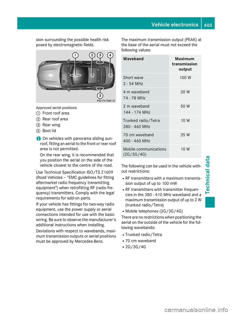
sion surrounding the possible health risk
posed by electromagnetic fields. Approved aerial positions
:
Front roof area
; Rear roof area
= Rear wing
? Boot lid
i On vehicles with panorama sliding sun-
roof, fitting an aerial to the front or rear roof
area is not permitted.
On the rear wing, it is recommended that
you position the aerial on the side of the
vehicle closest to the centre of the road.
Use Technical Specification ISO/TS 21609
(Road Vehicles – "EMC guidelines for fitting
aftermarket radio frequency transmitting
equipment") when retrofitting RF (radio fre-
quency) transmitters. Comply with the legal
requirements for add-on parts.
If your vehicle has fittings for two-way radio
equipment, use the power supply or aerial
connections intended for use with the basic
wiring. Be sure to observe the manufacturer's additional instructions when installing.
Deviations with respect to wavebands, maxi-
mum transmission outputs or aerial positions must be approved by Mercedes-Benz. The maximum transmission output (PEAK) at
the base of the aerial must not exceed the
following values: Waveband Maximum
transmission output Short wave
3 - 54 MHz 100 W
4 m waveband
74 - 78 MHz 30 W
2 m waveband
144 - 174 MHz 50 W
Trunked radio/Tetra
380 - 460 MHz 10 W
70 cm waveband
400 - 460 MHz 35 W
Mobile communications
(2G/3G/4G) 10 W
The following can be used in the vehicle with-
out restrictions:
R RF transmitters with a maximum transmis-
sion output of up to 100 mW
R RF transmitters with transmitter frequen-
cies in the 380 - 410 MHz waveband and a
maximum transmission output of up to 2 W(trunked radio/Tetra)
R Mobile telephones (3G/3G/4G)
There are no restrictions when positioning the aerial on the outside of the vehicle for the fol-
lowing wavebands:
R Trunked radio/Tetra
R 70 cm waveband
R 2G/3G/4G Vehicle electronics
403Technical data Z
Page 407 of 417

Identification plates
Vehicle identification plate with vehi-
cle identification number (VIN) X
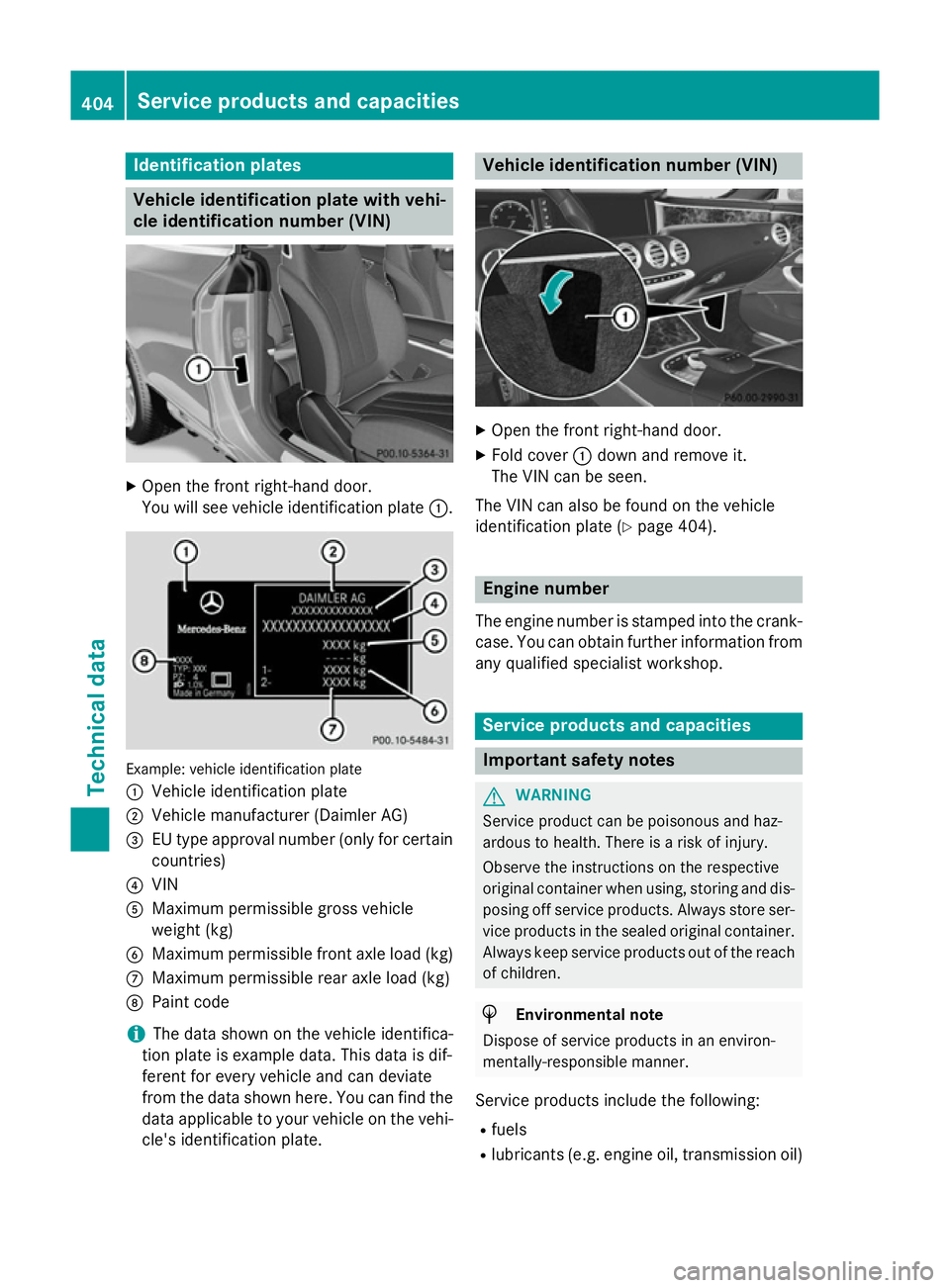
Open the front right-hand door.
You will see vehicle identification plate :.Example: vehicle identification plate
:
Vehicle identification plate
; Vehicle manufacturer (Daimler AG)
= EU type approval number (only for certain
countries)
? VIN
A Maximum permissible gross vehicle
weight (kg)
B Maximum permissible front axle load (kg)
C Maximum permissible rear axle load (kg)
D Paint code
i The data shown on the vehicle identifica-
tion plate is example data. This data is dif-
ferent for every vehicle and can deviate
from the data shown here. You can find the
data applicable to your vehicle on the vehi- cle's identification plate. Vehicle identification number (VIN)
X
Open the front right-hand door.
X Fold cover :down and remove it.
The VIN can be seen.
The VIN can also be found on the vehicle
identification plate (Y page 404). Engine number
The engine number is stamped into the crank-
case. You can obtain further information from any qualified specialist workshop. Service products and capacities
Important safety notes
G
WARNING
Service product can be poisonous and haz-
ardous to health. There is a risk of injury.
Observe the instructions on the respective
original container when using, storing and dis- posing off service products. Always store ser-
vice products in the sealed original container. Always keep service products out of the reach
of children. H
Environmental note
Dispose of service products in an environ-
mentally-responsible manner.
Service products include the following: R fuels
R lubricants (e.g. engine oil, transmission oil) 404
Service products and capacitiesTechnical data