2015 MERCEDES-BENZ S-CLASS COUPE boot
[x] Cancel search: bootPage 375 of 417

As soon as the vehicle is loaded:
X Prevent the vehicle from rolling away by
applying the electric parking brake.
X Shift the automatic transmission to posi-
tion P.
X Turn the key to position 0in the ignition
lock and remove it.
X Secure the vehicle. Notes for 4MATIC vehicles
! Vehicles with 4MATIC must not be towed
with the front or rear axle raised; otherwise,
the transmission may be damaged.
Vehicles with 4MATIC may either be towed
away with both axles on the ground or be loa- ded up and transported.
If the vehicle has transmission damage or
damage to the front or rear axle, have it trans-
ported on a transporter or trailer.
In the event of damage to the electrical
system: if the battery is defective, the auto-
matic transmission will be locked in position
P. To shift the automatic transmission to posi-
tion N, you must provide power to the vehi-
cle's electrical system in the same way as
when jump-starting (Y page 366).
Have the vehicle transported on a transporter
or trailer. Tow-starting (emergency engine
starting)
! Do not tow-start vehicles with automatic
transmission. You could otherwise damage the automatic transmission.
i Information on "Jump-starting"
(Y page 366). Electrical fuses
Important safety notes
G
WARNING
If you manipulate, bridge or replace a faulty
fuse with a fuse of a higher amperage, the
electric cables could be overloaded. This may result in a fire. There is a risk of an accident
and injury.
Always replace faulty fuses with specified new fuses of the correct amperage.
Blown fuses must be replaced with fuses of
the same rating, which you can recognise by
the colour and fuse rating. The fuse ratings
are listed in the fuse allocation chart.
The fuse allocation chart is on the fuse box in
the boot (Y page 374).
If the newly inserted fuse also blows, have the
cause traced and rectified at a qualified spe-
cialist workshop, e.g. a Mercedes-Benz Ser-
vice Centre.
! Only use fuses that have been approved
for Mercedes-Benz vehicles and which
have the correct fuse rating for the system
concerned. Otherwise, components or sys-
tems could be damaged.
The fuses in your vehicle disconnect faulty
circuits. If a fuse blows, all the components on the circuit and their functions will fail. Before replacing a fuse
X Safeguard the vehicle against rolling away
(Y page 181).
X Switch off all electrical consumers.
X Make sure that the ignition is switched off
(Y page 161).
or
X When using the key, turn the key to position
0 in the ignition lock and remove it
(Y page 161).
All indicator lamps in the instrument cluster
must be off. 372
Electrical fusesBreakdown assistance
Page 376 of 417

The fuses are located in various fuse boxes:
R fuse box on the driver's side of the dash-
board
R fuse box in the front-passenger footwell
R fuse box in the engine compartment on the
left-hand side of the vehicle, when viewed
in the direction of travel
R fuse box in the boot on the right-hand side
of the vehicle, when viewed in the direction
of travel Dashboard fuse box
! Do not use a pointed object such as a
screwdriver to open the cover in the dash-
board. You could damage the dashboard or
the cover.
! Make sure that no moisture can enter the
fuse box when the cover is open.
! When closing the cover, make sure that it
is lying correctly on the fuse box. Moisture
seeping in or dirt could otherwise impair
the operation of the fuses. X
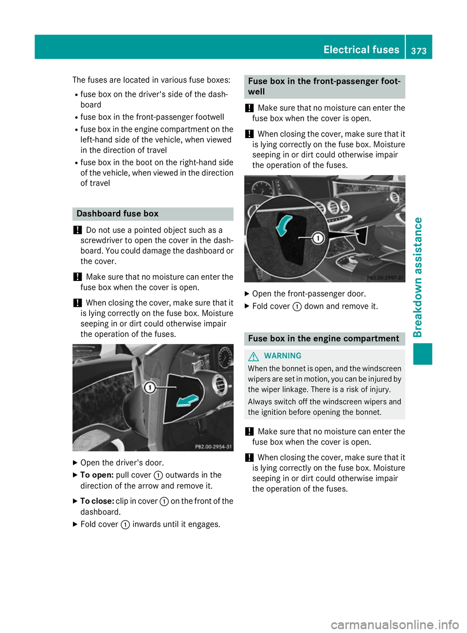
Open the driver's door.
X To open: pull cover :outwards in the
direction of the arrow and remove it.
X To close: clip in cover :on the front of the
dashboard.
X Fold cover :inwards until it engages. Fuse box in the front-passenger foot-
well
! Make sure that no moisture can enter the
fuse box when the cover is open.
! When closing the cover, make sure that it
is lying correctly on the fuse box. Moisture seeping in or dirt could otherwise impair
the operation of the fuses. X
Open the front-passenger door.
X Fold cover :down and remove it. Fuse box in the engine compartment
G
WARNING
When the bonnet is open, and the windscreen wipers are set in motion, you can be injured by
the wiper linkage. There is a risk of injury.
Always switch off the windscreen wipers and
the ignition before opening the bonnet.
! Make sure that no moisture can enter the
fuse box when the cover is open.
! When closing the cover, make sure that it
is lying correctly on the fuse box. Moisture
seeping in or dirt could otherwise impair
the operation of the fuses. Electrical fuses
373Breakdown assistance Z
Page 377 of 417

X
Open the bonnet.
X To open: release retaining clamps :and
remove cover ;. X
Remove any existing moisture from the
fuse box using a dry cloth.
X Undo screws =on the fuse box.
X Remove fuse box cover ?forwards.
X To close: check whether the seal is lying
correctly in cover ?.
X Insert cover ?at the rear of the fuse box
into the retainer.
X Fold down cover ?of the fuse box and
tighten screws =. Fuse box in the boot
! Make sure that no moisture can enter the
fuse box when the cover is open.
! When closing the cover, make sure that it
is lying correctly on the fuse box. Moisture seeping in or dirt could otherwise impair
the operation of the fuses. X
Open the boot lid.
X To open: release cover :at the top right
and left-hand sides with a flat object.
X Open cover :downwards in the direction
of the arrow.
i The fuse allocation chart is in a recess on
the side of the fuse box. You can find the
corresponding fuse rating and fuse type on the fuse allocation chart. 374
Electrical fusesBreakdown assistance
Page 391 of 417

used incorrectly, it could tip over while the
vehicle is raised.
R the jack is designed only to raise and hold
the vehicle for a short time while a wheel
is being changed. It is not suitable for per-
forming maintenance work under the vehi-
cle.
R avoid changing the wheel on uphill and
downhill slopes.
R before raising the vehicle, safeguard it from
rolling away by applying the parking brake
and positioning wheel chocks. Do not
release the parking brake while the vehicle is raised.
R the jack must be placed on a firm, flat and
non-slip surface. On a loose surface, a
large, flat load-bearing underlay must be
used. On a slippery surface, a non-slip
underlay must be used, e.g. rubber mats.
R do not use wooden blocks or similar
objects as a jack underlay. Otherwise, the
jack will not be able to achieve its load-
bearing capacity due to the restricted
height.
R make sure that the distance between the
underside of the tyres and the ground does not exceed 3 cm.
R never place your hands or feet under the
raised vehicle.
R do not lie under the vehicle.
R do not start the engine when the vehicle is
raised.
R do not open or close a door or the boot lid
when the vehicle is raised.
R make sure that no persons are present in
the vehicle when the vehicle is raised.
Vehicles with AMG wheels and hub caps:
the hub cap covers the wheel bolts. Before
you can unscrew the wheel bolts, you must
remove the hub cap. Two different variants
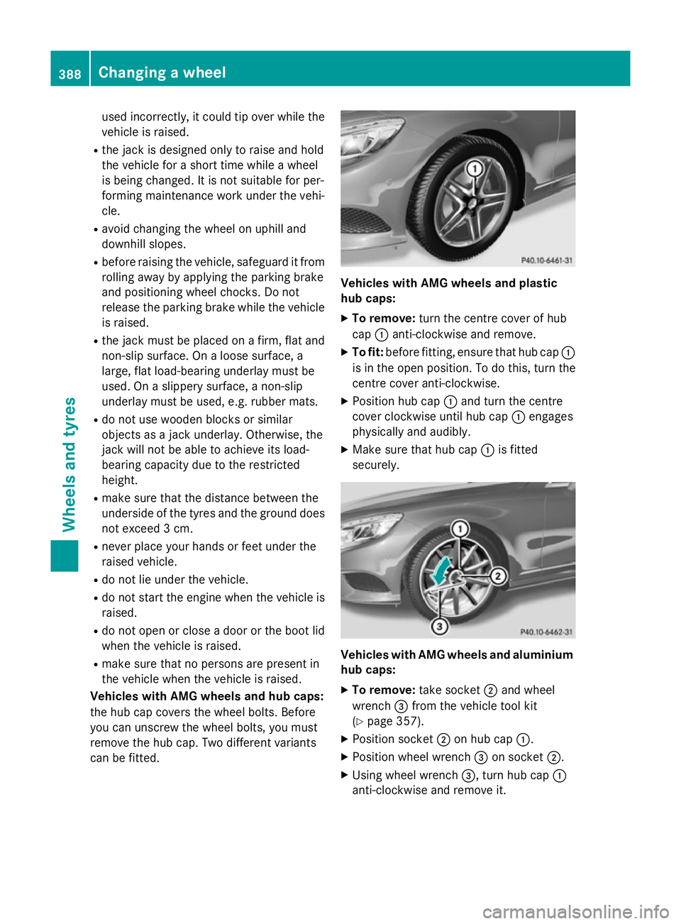
can be fitted. Vehicles with AMG wheels and plastic
hub caps:
X To remove: turn the centre cover of hub
cap :anti-clockwise and remove.
X To fit: before fitting, ensure that hub cap :
is in the open position. To do this, turn the
centre cover anti-clockwise.
X Position hub cap :and turn the centre
cover clockwise until hub cap :engages
physically and audibly.
X Make sure that hub cap :is fitted
securely. Vehicles with AMG wheels and aluminium
hub caps:
X To remove: take socket;and wheel
wrench =from the vehicle tool kit
(Y page 357).
X Position socket ;on hub cap :.
X Position wheel wrench =on socket ;.
X Using wheel wrench =, turn hub cap:
anti-clockwise and remove it. 388
Changing a wheelWheels and ty
res
Page 394 of 417

X
Place the ratchet ring spanner onto the
hexagon nut of the jack so that the letters
AB are visible.
X Turn the ratchet ring spanner until the vehi-
cle is once again standing firmly on the
ground.
X Place the jack to one side.
X Tighten the wheel bolts evenly in a cross-
wise pattern in the sequence indicated ( :
to A). The tightening torque must be
150 Nm.
X Turn the jack back to its initial position.
X Stow the jack and the rest of the tyre-
change tool kit in the boot again.
X Check the air pressure of the newly fitted
wheel and adjust accordingly.
Observe the recommended tyre pressure
(Y page 380).
i Vehicles with a tyre pressure control sys-
tem: all fitted wheels must be equipped
with functioning sensors for the tyre pres-
sure control system. Wheel and tyre combinations
General notes
! For safety reasons, Mercedes-Benz rec-
ommends that you only use tyres and
wheels which have been approved by
Mercedes-Benz specifically for your vehi-
cle. These are specially adapted to the control
systems, such as ABS or ESP
®
and are
marked as follows:
R MO = Mercedes-Benz Original
R MOE = Mercedes-Benz Original Extended
(tyres featuring run-flat characteristics)
R MO1 = Mercedes-Benz Original (only cer-
tain AMG tyres)
Mercedes-Benz Original Extended tyres
may only be used on wheels that have been
specifically approved by Mercedes-Benz.
Only use tyres, wheels or accessories tes-
ted and approved by Mercedes-Benz. Cer-
tain characteristics, e.g. handling, vehicle
noise emissions or fuel consumption, may
otherwise be adversely affected. In addi-
tion, when driving with a load, tyre dimen-
sion variations could cause the tyres to
come into contact with the bodywork and
axle components. This could result in dam- age to the tyres or the vehicle.
Mercedes-Benz accepts no liability for
damage resulting from the use of tyres,
wheels or accessories other than those tes- ted and approved.
Further information about wheels, tyres
and approved combinations can be
obtained from any qualified specialist
workshop.
! Retreaded tyres are neither tested nor
recommended by Mercedes-Benz, since
previous damage cannot always be detec-
ted on retreaded tyres. As a result,
Mercedes-Benz cannot guarantee vehicle
safety if retreaded tyres are fitted. Do not fit
used tyres if you have no information about their previous usage.
! Large wheels: the lower the section width
for a certain wheel size, the lower the ride
comfort is on poor road surfaces. Roll com-
fort and suspension comfort are reduced
and the risk of damage to the wheels and
tyres as a result of driving over obstacles
increases. Wheel and tyre combinations
391Wheels and tyres Z
Page 406 of 417

sion surrounding the possible health risk
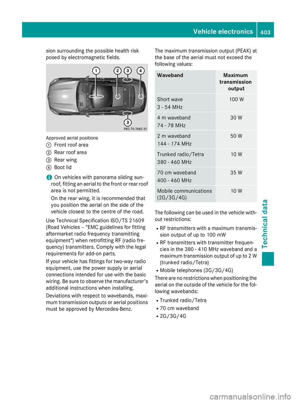
posed by electromagnetic fields. Approved aerial positions
:
Front roof area
; Rear roof area
= Rear wing
? Boot lid
i On vehicles with panorama sliding sun-
roof, fitting an aerial to the front or rear roof
area is not permitted.
On the rear wing, it is recommended that
you position the aerial on the side of the
vehicle closest to the centre of the road.
Use Technical Specification ISO/TS 21609
(Road Vehicles – "EMC guidelines for fitting
aftermarket radio frequency transmitting
equipment") when retrofitting RF (radio fre-
quency) transmitters. Comply with the legal
requirements for add-on parts.
If your vehicle has fittings for two-way radio
equipment, use the power supply or aerial
connections intended for use with the basic
wiring. Be sure to observe the manufacturer's additional instructions when installing.
Deviations with respect to wavebands, maxi-
mum transmission outputs or aerial positions must be approved by Mercedes-Benz. The maximum transmission output (PEAK) at
the base of the aerial must not exceed the
following values: Waveband Maximum
transmission output Short wave
3 - 54 MHz 100 W
4 m waveband
74 - 78 MHz 30 W
2 m waveband
144 - 174 MHz 50 W
Trunked radio/Tetra
380 - 460 MHz 10 W
70 cm waveband
400 - 460 MHz 35 W
Mobile communications
(2G/3G/4G) 10 W
The following can be used in the vehicle with-
out restrictions:
R RF transmitters with a maximum transmis-
sion output of up to 100 mW
R RF transmitters with transmitter frequen-
cies in the 380 - 410 MHz waveband and a
maximum transmission output of up to 2 W(trunked radio/Tetra)
R Mobile telephones (3G/3G/4G)
There are no restrictions when positioning the aerial on the outside of the vehicle for the fol-
lowing wavebands:
R Trunked radio/Tetra
R 70 cm waveband
R 2G/3G/4G Vehicle electronics
403Technical data Z
Page 413 of 417

!
Do not use distilled or de-ionised water in
the washer fluid reservoir. Otherwise, the
level sensor may be damaged.
! Only the washer fluids SummerFit and
WinterFit can be mixed. Otherwise, the
spraying nozzles could become blocked.
At temperatures above freezing:
X Fill the washer fluid reservoir with a mixture
of water and washer fluid, e.g. MB Sum-
merFit.
Mix 1 part MB SummerFit to 100 parts water.
At temperatures below freezing:
X Fill the washer fluid reservoir with a mixture
of water and washer fluid, e.g. MB Winter-
Fit.
The correct mixing ratio can be taken from
the information on the antifreeze protec-
tion container.
i Add washer fluid concentrate, e.g. MB
SummerFit or MB WinterFit, to the washer
fluid all year round. Vehicle data
General notes
Please note that for the specified vehicle
data: R the heights specified may vary as a result
of:
- tyres
- load
- condition of the suspension
- optional equipment
R optional equipment reduces the maximum
payload
R vehicle-specific weight information can be
found on the vehicle identification plate
(Y page 404).
R only for certain countries: you can find vehi-
cle-specific vehicle data in the COC docu-
ments (CERTIFICATE OF CONFORMITY). These documents are delivered with your
vehicle. Dimensions and weights
Model
: :
Opening height Mercedes‑AMG
vehicles
1755 mm
All other models
1746 mm
Mercedes‑AMG vehicles
Vehicle length
5044 mm
Vehicle width including
exterior mirrors
2108 mm
Vehicle width excluding
exterior mirrors
1913 mm
Vehicle height
1422 mm
Wheelbase
2945 mm
Maximum boot load
100 kg
All other models
Vehicle length
5027 mm
Vehicle width including
exterior mirrors
2108 mm
Vehicle width excluding
exterior mirrors
1899 mm
Vehicle height
1411 mm410
Vehicle dataTechnical data
Page 414 of 417

All other models
Wheelbase
2945 mm
Maximum boot load
100 kg Vehicle data
411Technical data Z