2015 MERCEDES-BENZ S-CLASS COUPE trailer
[x] Cancel search: trailerPage 215 of 417

X
If indicator lamp ;
;is not lit: press but-
ton :.
Indicator lamp ;lights up. You have selec-
ted "Comfort mode".
All vehicles except AMG vehicles: the
AIRMATIC COMFORT AIRMATIC COMFORT message appears in
the multifunction display.
AMG vehicles: theAMG Ride Control AMG Ride Control
COMFORT
COMFORT message appears in the multi-
function display.
All vehicles except AMG vehicles: if the
driving speed is higher than 160 km/h, the
vehicle is automatically lowered by 10 mm.
Load compensation The vehicle can compensate differences in
the vehicle level by raising or lowering the
axles. 4MATIC (permanent all-wheel drive)
4MATIC ensures that all four wheels are per-
manently driven. Together with ESP ®
, it
improves the traction of your vehicle when-
ever a drive wheel spins due to insufficient
grip.
If you fail to adapt your driving style, 4MATIC
can neither reduce the risk of accident nor
override the laws of physics. 4MATIC cannot
take account of road, weather and traffic con- ditions. 4MATIC is only an aid. You are
responsible for the distance to the vehicle in
front, for vehicle speed, for braking in good
time, and for staying in the lane.
If a drive wheel spins due to insufficient grip:
R when pulling away, only depress the accel-
erator pedal as far as is necessary.
R accelerate less when driving
! Never tow the vehicle with one axle
raised. This may damage the transfer case.
Damage of this sort is not covered by the
Mercedes-Benz implied warranty. All
wheels must remain either on the ground or be fully raised. Observe the instructions for towing the vehicle with all wheels in full
contact with the ground.
i In wintry driving conditions, the maximum
effect of 4MATIC can only be achieved if
you use winter tyres (M+S tyres),with snow
chains if necessary. PARKTRONIC
Important safety notes PARKTRONIC is an electronic parking aid with
ultrasonic sensors. It monitors the area
around your vehicle using six sensors in the
front bumper and six sensors in the rear
bumper. PARKTRONIC indicates visually and
audibly the distance between your vehicle
and an object.
PARKTRONIC is only an aid. It is not a substi-
tute for your attention to the immediate sur-
roundings. The responsibility for safe
manoeuvring and parking remains with you.
Make sure that there are no persons, animals
or objects in range while manoeuvring and
parking.
! When parking, pay particular attention to
objects above or below the sensors, such
as flower pots or trailer drawbars.
PARKTRONIC does not detect such objects
when they are in the immediate vicinity of
the vehicle. You could damage the vehicle
or the objects.
The sensors may not detect snow and
objects which absorb ultrasonic sources.
Ultrasonic sources, such as an automatic
car wash, a lorry's compressed-air brakes
or a pneumatic drill, could cause
PARKTRONIC to malfunction.
PARKTRONIC may not function correctly on uneven terrain.
PARKTRONIC is activated automatically when you:
R switch on the ignition
R shift the transmission to position D,Ror N 212
Driving systemsDriving and parking
Page 219 of 417
Parking tips:
R on narrow roads, drive as closely as possi-
ble past the parking space.
R parking spaces that are littered or over-
grown might be identified or measured
incorrectly.
R parking spaces that are partially occupied
by trailer drawbars might not be identified
as such or be measured incorrectly.
R snowfall or heavy rain may lead to a parking
space being measured inaccurately.
R pay attention to the PARKTRONIC
(Y page 214) warning messages during the
parking procedure.
R you can intervene in the steering procedure
to correct it at any time. Active Parking
Assist will then be cancelled.
R when transporting a load which protrudes
from your vehicle, you should not use
Active Parking Assist.
R never use Active Parking Assist when snow
chains are fitted.
R make sure that the tyre pressures are
always correct. This has a direct influence
on the parking characteristics of the vehi-
cle.
Use Active Parking Assist for parking spaces
that are:
R parallel or at right angles to the direction of
travel
R on straight roads, not bends.
R on the same level as the road, e.g. not on
the pavement.
Detecting parking spaces Objects located above the height range of
Active Parking Assist will not be detected
when the parking space is measured. These
are not taken into account when the parking
procedure is calculated, e.g. overhanging
loads, tail sections or loading ramps of goods vehicles. G
WARNING
If there are objects above the detection range:
R Active Park Assist may steer too early
R the vehicle may not stop in front of these
objects
This could cause a collision. There is a risk of
an accident.
If objects are located above the detection
range, stop and deactivate Active Parking
Assist.
For further information on the detection
range (Y page 213).
Active Parking Assist does not assist you
parking in spaces at right angles to the direc-
tion of travel if:
R two parking spaces are located directly
next to one another
R the parking space is directly next to a low
obstacle such as a low kerb
R you forward park
Active Parking Assist does not assist you
parking in spaces that are parallel or at right
angles to the direction of travel if:
R the parking space is on a kerb
R the system reads the parking space as
being blocked, for example by foliage or
grass paving blocks
R the area is too small for the vehicle to
manoeuvre into
R the parking space is bordered by an obsta-
cle, e.g. a tree, a post or a trailer 216
Driving systemsDriving and parking
Page 224 of 417
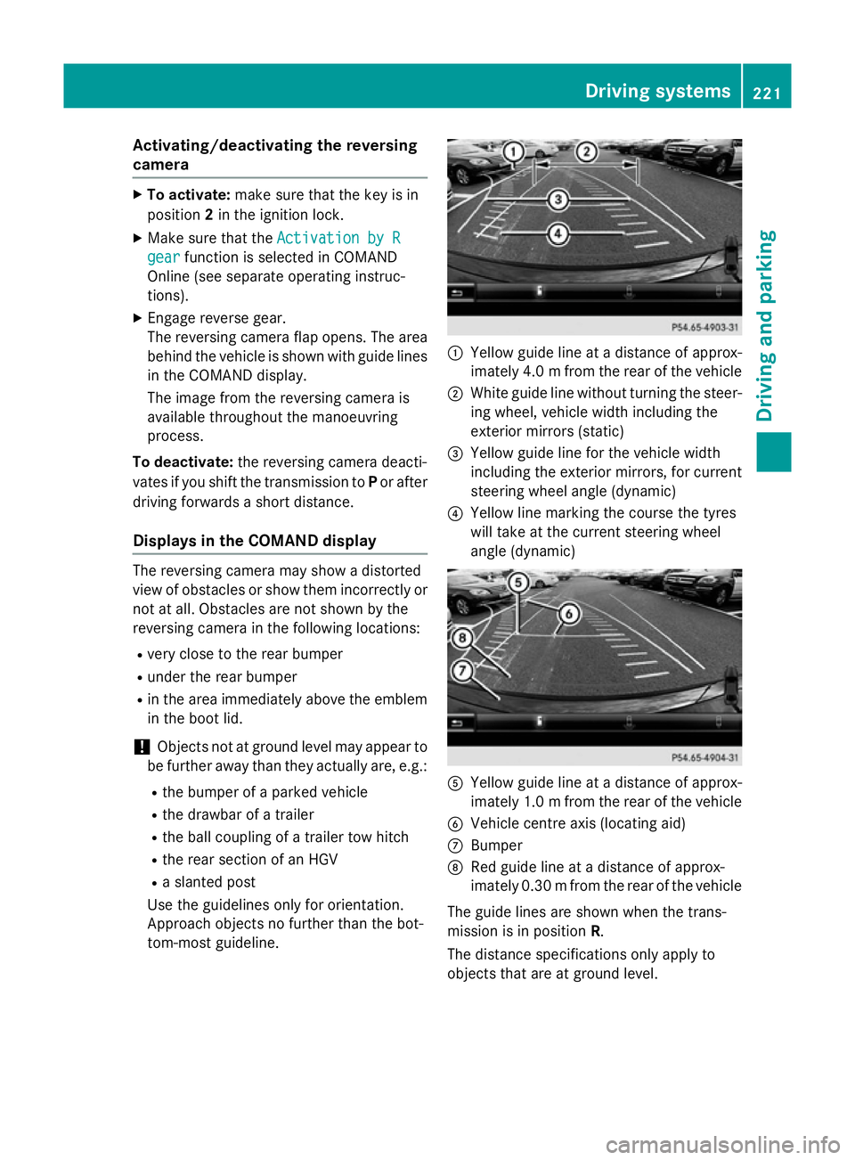
Activating/deactivating the reversing
camera X
To activate: make sure that the key is in
position 2in the ignition lock.
X Make sure that the Activation by R
Activation by R
gear
gear function is selected in COMAND
Online (see separate operating instruc-
tions).
X Engage reverse gear.
The reversing camera flap opens. The area
behind the vehicle is shown with guide lines in the COMAND display.
The image from the reversing camera is
available throughout the manoeuvring
process.
To deactivate: the reversing camera deacti-
vates if you shift the transmission to Por after
driving forwards a short distance.
Displays in the COMAND display The reversing camera may show a distorted
view of obstacles or show them incorrectly or not at all. Obstacles are not shown by the
reversing camera in the following locations:
R very close to the rear bumper
R under the rear bumper
R in the area immediately above the emblem
in the boot lid.
! Objects not at ground level may appear to
be further away than they actually are, e.g.:
R the bumper of a parked vehicle
R the drawbar of a trailer
R the ball coupling of a trailer tow hitch
R the rear section of an HGV
R a slanted post
Use the guidelines only for orientation.
Approach objects no further than the bot-
tom-most guideline. :
Yellow guide line at a distance of approx-
imately 4.0 mfrom the rear of the vehicle
; White guide line without turning the steer-
ing wheel, vehicle width including the
exterior mirrors (static)
= Yellow guide line for the vehicle width
including the exterior mirrors, for current
steering wheel angle (dynamic)
? Yellow line marking the course the tyres
will take at the current steering wheel
angle (dynamic) A
Yellow guide line at a distance of approx-
imately 1.0 mfrom the rear of the vehicle
B Vehicle centre axis (locating aid)
C Bumper
D Red guide line at a distance of approx-
imately 0.30 mfrom the rear of the vehicle
The guide lines are shown when the trans-
mission is in position R.
The distance specifications only apply to
objects that are at ground level. Driving systems
221Driving and parking Z
Page 229 of 417
R
full-screen view with image from the
front camera
R full-screen view with image from the
reversing camera.
X To switch off: press button:again.
Activating the 360° camera using
COMAND Online X
Press the Øbutton in the centre con-
sole.
The vehicle menu appears.
X To select the 360° camera: turn and press
the controller.
The following appears depending on
whether transmission position Dor Ris
selected:
R a split-screen with top view and the
image from the front camera or
R a split-screen with top view and the
image from the reversing camera.
Further information on the COMAND control-
ler can be found in the separate operating
instructions.
Activating the 360° camera using
reverse gear You can show images from the 360° camera
automatically by engaging reverse gear.
X Make sure that the key is in position 2in the
ignition lock.
X Make sure that the Activation by R Activation by R
gear
gear function is selected in COMAND
Online (see separate operating instruc-
tions).
X To show the 360° camera image: engage
reverse gear.
The area behind the vehicle is shown in the
COMAND display in split-screen mode. You see the top view of the vehicle and the
image from the reversing camera. Selecting the split-screen and full
screen displays Switching between split screen views:
X To switch to the line with the vehicle icons:
slide ZVthe controller.
X To select a vehicle icon: turn the controller.
Switching to full screen mode:
X Select 180° view
180° view by turning and pressing
the controller.
i The 180° option is only available in the
following views:
R Top view with image from the reversing
camera
R Top view with image from the front cam-
era
Displays in the COMAND display Important safety notes
The camera system may show a distorted
view of obstacles or show them incorrectly or
not at all. Obstacles are not shown by the
system in the following locations:
R under the front and rear bumpers
R very close to the front and rear bumpers
R in the area immediately above the handle
on the boot lid
R very close to the exterior mirrors
R in the transitional areas between the vari-
ous cameras in the virtual top view
! Objects not at ground level may appear to
be further away than they actually are, e.g.:
R the bumper of a parked vehicle
R the drawbar of a trailer
R the ball coupling of a trailer tow hitch
R the rear section of an HGV
R a slanted post
Use the guidelines only for orientation.
Approach objects no further than the bot-
tom-most guideline. 226
Driving systemsDriving an
d parking
Page 372 of 417
X
First, remove the jump leads from earth point Band negative terminal A, then from pos-
itive clamp =and positive terminal ?. Begin each time at the contacts on your own vehicle
first.
X Close cover Cof positive clamp =after removing the jump leads.
X Replace the earth point cover. Make sure all mountings for the fasteners are positioned
precisely beneath the corresponding recesses in the cover.
X Press fasteners :into the mountings until they engage.
X Have the battery checked at a qualified specialist workshop.
Jump-starting is not considered to be a normal operating condition.
i Jump-starting cables and further information regarding jump starting can be obtained at
any qualified specialist workshop. Towing away and tow-starting
Important safety notes
G
WARNING
Safety-relevant functions are restricted or not
available if:
R the engine is not running.
R the brake system or the power steering is
malfunctioning
R the voltage supply or the vehicle's electrical
system is malfunctioning.
If your vehicle is towed, significantly greater
force may be required to steer the vehicle or
to brake. There is a risk of an accident.
In such circumstances, use a towing bar.
Make sure that the steering is moving freely
before towing. G
WARNING
If the steering wheel lock is engaged, the vehi- cle can no longer be steered. There is a risk of
an accident.
Always switch on the ignition when towing
with a tow rope or a towing bar. G
WARNING
When towing or tow-starting another vehicle
and its weight is greater than the permissible gross weight of your vehicle, the:
R towing eye may be torn off
R car/trailer combination may swerve or
even overturn
There is a risk of an accident.
When towing or tow-starting another vehicle,
its weight should not be greater than the per- missible gross weight of your vehicle.
Information on your vehicle's gross vehicle
weight rating can be found on the vehicle
identification plate (Y page 404).
! When COLLISION PREVENTION ASSIST
PLUS, DISTRONIC PLUS or the HOLD func- tion is activated, the vehicle brakes auto-
matically in certain situations. To avoid
damage to the vehicle, deactivate these
systems in the following or similar situa-
tions:
R when towing away
R in a car wash
! Make sure that the electric parking brake
is released. If the electric parking brake is
faulty, visit a qualified specialist workshop.
! Secure the tow rope or tow bar to the
towing eye only. The vehicle may otherwise
be damaged. Towing away and tow-starting
369Breakdown assistance Z
Page 373 of 417
!
Observe the following points when towing
with a tow rope:
R secure the tow rope on the same side on
both vehicles.
R make sure that the tow rope is not longer
than legally permitted. Mark the tow rope
in the middle, e.g. with a white cloth
(30 x 30 cm). This makes other road
users aware that a vehicle is being
towed.
R only secure the tow rope to the towing
eye.
R observe the brake lamps of the towing
vehicle while driving. Always maintain a
distance so that the tow rope does not
sag.
R do not use steel cables or chains to tow
your vehicle. You could otherwise dam-
age the vehicle.
! Do not use the towing eyes for recovery
purposes as this could damage the vehicle.
If in doubt, recover the vehicle with a crane.
! When towing, pull away slowly and
smoothly. If the tractive power is too high,
the vehicles could be damaged.
! Shift the automatic transmission to
Nand
do not open the driver's or front passeng-
er's door during towing. The automatic
transmission may otherwise shift to posi-
tion P, which could damage the transmis-
sion.
! You may tow the vehicle for a maximum of
50km. A towing speed of 50 km/h must not be exceeded.
For towing distances over 50 km, the entire
vehicle must be lifted up and transported.
Observe the legal requirements for the rele-
vant countries when towing.
It is better to have the vehicle transported
than to have it towed.
If the vehicle has suffered transmission dam-
age, have it transported on a transporter or
trailer. The automatic transmission must be in posi-
tion
Nwhen the vehicle is being towed away.
If the automatic transmission cannot be shif- ted to position N, have the vehicle transpor-
ted on a transporter or trailer.
The battery must be connected and charged. Otherwise, you:
R cannot turn the key in the ignition lock to
position 2
R cannot release the electric parking brake
R cannot shift the automatic transmission to
position N
i Deactivate the automatic locking feature
before the vehicle is towed away
(Y page 92). You could otherwise be locked
out when pushing or towing the vehicle.
i Deactivate tow-away protection before
the vehicle is towed away (Y page 81). Fitting/removing the towing eye
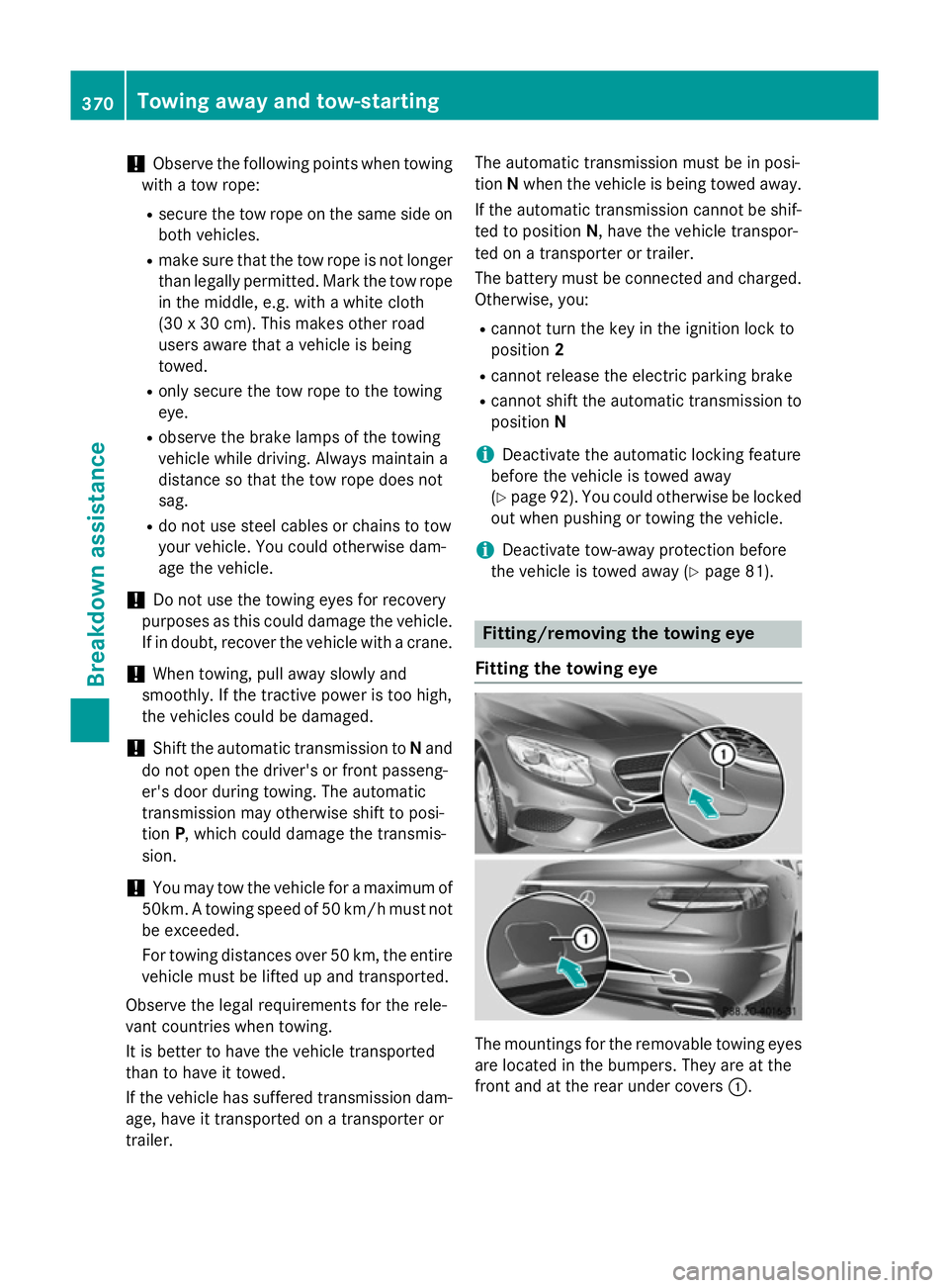
Fitting the towing eye The mountings for the removable towing eyes
are located in the bumpers. They are at the
front and at the rear under covers :.370
Towing away and tow-startingBreakdown assistance
Page 374 of 417

X
Remove the towing eye from the vehicle
tool kit/stowage tray (Y page 357).
X Press the mark on cover :inwards in the
direction of the arrow.
X Remove cover :from the opening.
X Screw in the towing eye clockwise as far as
it will go and tighten it.
Removing the towing eye X
Loosen the towing eye and unscrew it.
X Attach cover :to the bumper and press
until it engages.
X Place the towing eye in the vehicle tool kit/
stowage tray. Towing the vehicle with both axles on
the ground
It is important that you observe the safety
instructions when towing away your vehicle
(Y page 369).
The automatic transmission automatically
shifts to position Pwhen you open the driver's
or front-passenger door or when you remove the key from the ignition lock.
In order to ensure that the automatic trans-
mission stays in position Nwhen towing the
vehicle, you must observe the following
points:
X You must use the key instead of the Start/
Stop button (Y page 161).
X Make sure that the vehicle is stationary and
that the key is in position 0in the ignition
lock.
X Turn the key to position 2in the ignition
lock.
X Depress and hold the brake pedal.
X Shift the automatic transmission to posi-
tion N.
X Release the brake pedal.
X Release the electric parking brake. X
Leave the key in position 2in the ignition
lock.
X Switch on the hazard warning lamps
(Y page 128).
i In order to signal a change of direction
when towing the vehicle with the hazard
warning lamps switched on, use the com-
bination switch as usual. In this case, only
the turn signals for the desired direction
flash. When you reset the combination
switch, the hazard warning lamps start
flashing again. Towing the vehicle away with the rear
axle raised
Only vehicles without 4MATIC can be
towed away with the rear axle raised.
! The ignition must be switched off if you
are towing the vehicle with the rear axle
raised. Intervention by ESP ®
could other-
wise damage the brake system.
! Vehicles with 4MATIC must not be towed
with the front or rear axle raised; otherwise,
the transmission may be damaged.
! Vehicles with automatic transmission
must not be towed with the rear axle raised.
The car/trailer combination may otherwise swerve or even overturn. Transporting the vehicle
! You may only secure the vehicle by the
wheels, not by parts of the vehicle such as
axle or steering components. Otherwise,
the vehicle could be damaged.
The towing eye can be used to pull the vehicle
onto a trailer or transporter for transporta-
tion.
X Turn the key to position 2in the ignition
lock.
X Shift the automatic transmission to posi-
tion N. Towing away and tow-starting
371Breakdown assistance Z
Page 375 of 417

As soon as the vehicle is loaded:
X Prevent the vehicle from rolling away by
applying the electric parking brake.
X Shift the automatic transmission to posi-
tion P.
X Turn the key to position 0in the ignition
lock and remove it.
X Secure the vehicle. Notes for 4MATIC vehicles
! Vehicles with 4MATIC must not be towed
with the front or rear axle raised; otherwise,
the transmission may be damaged.
Vehicles with 4MATIC may either be towed
away with both axles on the ground or be loa- ded up and transported.
If the vehicle has transmission damage or
damage to the front or rear axle, have it trans-
ported on a transporter or trailer.
In the event of damage to the electrical
system: if the battery is defective, the auto-
matic transmission will be locked in position
P. To shift the automatic transmission to posi-
tion N, you must provide power to the vehi-
cle's electrical system in the same way as
when jump-starting (Y page 366).
Have the vehicle transported on a transporter
or trailer. Tow-starting (emergency engine
starting)
! Do not tow-start vehicles with automatic
transmission. You could otherwise damage the automatic transmission.
i Information on "Jump-starting"
(Y page 366). Electrical fuses
Important safety notes
G
WARNING
If you manipulate, bridge or replace a faulty
fuse with a fuse of a higher amperage, the
electric cables could be overloaded. This may result in a fire. There is a risk of an accident
and injury.
Always replace faulty fuses with specified new fuses of the correct amperage.
Blown fuses must be replaced with fuses of
the same rating, which you can recognise by
the colour and fuse rating. The fuse ratings
are listed in the fuse allocation chart.
The fuse allocation chart is on the fuse box in
the boot (Y page 374).
If the newly inserted fuse also blows, have the
cause traced and rectified at a qualified spe-
cialist workshop, e.g. a Mercedes-Benz Ser-
vice Centre.
! Only use fuses that have been approved
for Mercedes-Benz vehicles and which
have the correct fuse rating for the system
concerned. Otherwise, components or sys-
tems could be damaged.
The fuses in your vehicle disconnect faulty
circuits. If a fuse blows, all the components on the circuit and their functions will fail. Before replacing a fuse
X Safeguard the vehicle against rolling away
(Y page 181).
X Switch off all electrical consumers.
X Make sure that the ignition is switched off
(Y page 161).
or
X When using the key, turn the key to position
0 in the ignition lock and remove it
(Y page 161).
All indicator lamps in the instrument cluster
must be off. 372
Electrical fusesBreakdown assistance