2015 MERCEDES-BENZ S-CLASS COUPE boot
[x] Cancel search: bootPage 228 of 417
The 360° camera will not function or will
function only in a limited manner:
R if the doors are open
R if the exterior mirrors are folded in
R if the boot lid is open
R in heavy rain, snow or fog
R at night or in very dark places
R if the cameras are exposed to very bright
light
R if the area is lit by fluorescent bulbs or LED
lighting (the display may flicker)
R if the camera lenses mist up, e.g. when
driving into a heated garage in winter, caus-
ing a rapid change in temperature
R if the camera lenses are dirty or covered.
Observe the notes on cleaning
(Y page 350)
R if the vehicle components in which the
cameras are fitted are damaged. In this
event, have the camera position and setting
checked at a qualified specialist workshop.
Do not use the 360° under such circumstan-
ces. You could otherwise injure others or
damage objects when parking the vehicle.
The guide lines in the COMAND display show
the distances to your vehicle. The distances
only apply to road level.
i The camera in the rear area is protected
from raindrops and dust by means of a flap.
This flap opens when the 360° camera is
activated.
The flap closes again when:
R you have finished the manoeuvring proc-
ess
R you switch off the engine
R you open the boot
See the notes on cleaning (Y page 350).
For technical reasons, the flap may remain
open briefly after the 360° camera has
been deactivated. On vehicles with height-adjustable chassis,
depending on technical conditions, leaving
the standard height can result in:
R inaccuracies in the guide lines
R inaccuracies in the display of generated
images (top view)
Activation conditions The 360° camera image can be displayed if:
R COMAND Online is switched on (see the
separate operating instructions)
R the 360° camera 360° camera function is switched on
i If the 360° camera is activated at speeds
above approximately 30 km/h, a warning
message appears.
The warning message disappears if:
R the vehicle's speed falls below approx-
imately 30 km/h. The 360° camera is
then activated.
R the message is confirmed with the %
button.
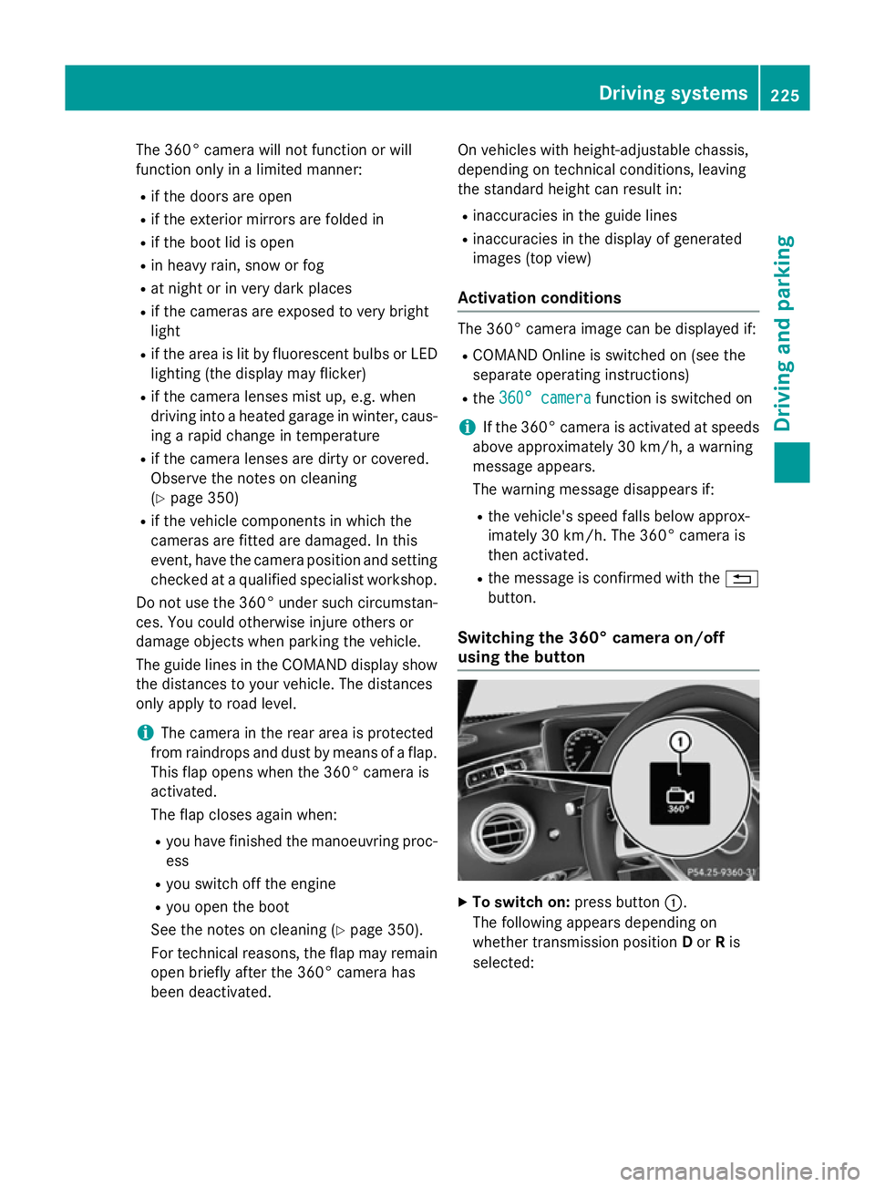
Switching the 360° camera on/off
using the button X
To switch on: press button:.
The following appears depending on
whether transmission position Dor Ris
selected: Driving systems
225Driving and parking Z
Page 229 of 417
R
full-screen view with image from the
front camera
R full-screen view with image from the
reversing camera.
X To switch off: press button:again.
Activating the 360° camera using
COMAND Online X
Press the Øbutton in the centre con-
sole.
The vehicle menu appears.
X To select the 360° camera: turn and press
the controller.
The following appears depending on
whether transmission position Dor Ris
selected:
R a split-screen with top view and the
image from the front camera or
R a split-screen with top view and the
image from the reversing camera.
Further information on the COMAND control-
ler can be found in the separate operating
instructions.
Activating the 360° camera using
reverse gear You can show images from the 360° camera
automatically by engaging reverse gear.
X Make sure that the key is in position 2in the
ignition lock.
X Make sure that the Activation by R Activation by R
gear
gear function is selected in COMAND
Online (see separate operating instruc-
tions).
X To show the 360° camera image: engage
reverse gear.
The area behind the vehicle is shown in the
COMAND display in split-screen mode. You see the top view of the vehicle and the
image from the reversing camera. Selecting the split-screen and full
screen displays Switching between split screen views:
X To switch to the line with the vehicle icons:
slide ZVthe controller.
X To select a vehicle icon: turn the controller.
Switching to full screen mode:
X Select 180° view
180° view by turning and pressing
the controller.
i The 180° option is only available in the
following views:
R Top view with image from the reversing
camera
R Top view with image from the front cam-
era
Displays in the COMAND display Important safety notes
The camera system may show a distorted
view of obstacles or show them incorrectly or
not at all. Obstacles are not shown by the
system in the following locations:
R under the front and rear bumpers
R very close to the front and rear bumpers
R in the area immediately above the handle
on the boot lid
R very close to the exterior mirrors
R in the transitional areas between the vari-
ous cameras in the virtual top view
! Objects not at ground level may appear to
be further away than they actually are, e.g.:
R the bumper of a parked vehicle
R the drawbar of a trailer
R the ball coupling of a trailer tow hitch
R the rear section of an HGV
R a slanted post
Use the guidelines only for orientation.
Approach objects no further than the bot-
tom-most guideline. 226
Driving systemsDriving an
d parking
Page 302 of 417
Display messages
Possible causes/consequences and
M
MSolutions Auxiliary battery
Auxiliary battery
malfunction malfunction The auxiliary battery for the transmission is no longer being
charged.
X Consult a qualified specialist workshop at the next opportunity.
X Until then, set the selector lever to position Pbefore you switch
off the engine.
X Before leaving the vehicle, apply the electric parking brake. N N The boot lid is open.
X Close the boot lid. M
M The bonnet is open. A warning tone also sounds.
G WARNING
The open bonnet may then block your view when the vehicle is in
motion.
There is a risk of an accident.
X Pull over and stop the vehicle safely as soon as possible, paying
attention to road and traffic conditions.
X Safeguard the vehicle against rolling away (Y page 181).
X Close the bonnet. Active bonnet mal‐ Active bonnet mal‐
function See Own‐ function See Own‐
er's Manual er's Manual The active bonnet (pedestrian protection) is not active due to a
malfunction or because it has already been triggered.
X Consult a qualified specialist workshop. C C At least one door is open. A warning tone also sounds.
X Close all doors. _
Front left seat Front left seat
backrest not backrest not
locked locked
orFront
Front
right seat back‐
right seat back‐
rest not locked
rest not locked The driver's or front-passenger seat backrest is not engaged. A
warning tone also sounds.
X Push the backrest back until it engages. &
inoperative Bat‐ inoperative Bat‐
tery low tery low the on-board voltage is too low The auxiliary heating (Y
page 149)
has switched itself off. The auxiliary heating cannot be switched
on.
X Drive for a considerable distance.
The battery charges. The auxiliary heating is operational again as
soon as the on-board electrical system voltage is sufficient. Display
messages
299On-board computer and displays Z
Page 319 of 417
Useful information
i This Owner's Manual describes all mod-
els, series and optional equipment for your
vehicle that were available at the time of
going to press. National variations are pos- sible. Note that your vehicle may not be
equipped with all of the functions descri-
bed. This is also the case for systems and
functions relevant to safety.
i Read the information on qualified special-
ist workshops: (Y page 26). Stowage areas
Loading guidelines
G
WARNING
Combustion engines emit poisonous exhaust
gases such as carbon monoxide. Exhaust
gases can enter the vehicle interior if the boot
lid is open when the engine is running, espe-
cially if the vehicle is in motion. There is a risk of poisoning.
Always switch off the engine before opening
the boot lid. Never drive with the boot lid
open. G
WARNING
If objects, luggage or loads are not secured or not secured sufficiently, they could slip, tip
over or be flung around and thereby hit vehicle
occupants. There is a risk of injury, especially when braking or abruptly changing directions.
Always store objects so that they cannot be
flung around. Secure objects, luggage or
loads against slipping or tipping before the
journey. G
WARNING
The exhaust tail pipe and tail pipe trim can
become very hot. If you come into contact
with these parts of the vehicle, you could burn
yourself. There is a risk of injury. Always be particularly careful around the
exhaust tail pipe and the tail pipe trim. Allow
these components to cool down before touch-
ing them.
The handling characteristics of a laden vehi-
cle are dependent on the distribution of the
load within the vehicle. For this reason, you
should observe the following notes when
transporting a load:
R never exceed the maximum permissible
gross vehicle weight or the permissible axle
loads for the vehicle (including occupants).
R the boot is the preferred place to carry
objects.
R position heavy loads as far forwards as pos-
sible and as low down in the boot as pos-
sible.
R the load must not protrude above the upper
edge of the seat backrests.
R always place the load behind unoccupied
seats if possible.
R secure the load with sufficiently strong and
wear-resistant lashing material. Pad sharp
edges for protection.
i Load restraints are available at any quali-
fied specialist workshop, e.g. a Mercedes-
Benz Service Centre. Stowage compartments
Important safety notes G
WARNING
If you do not correctly store objects in the
vehicle interior, they can slip or be flung
around, thus striking vehicle occupants.
There is a risk of injury, especially when brak- ing or abruptly changing directions.
R Always store objects so that they cannot be
flung around in these or in similar situa-
tions.
R Always make sure that objects do not pro-
trude from stowage compartments, lug-
gage nets or stowage nets. 316
Stowage areasStowing and features
Page 320 of 417
R
Close lockable stowage compartments
while driving.
R Stow and secure objects that are heavy,
hard, pointy, sharp-edged, fragile or too
large in the boot.
Observe the loading guidelines (Y page 316).
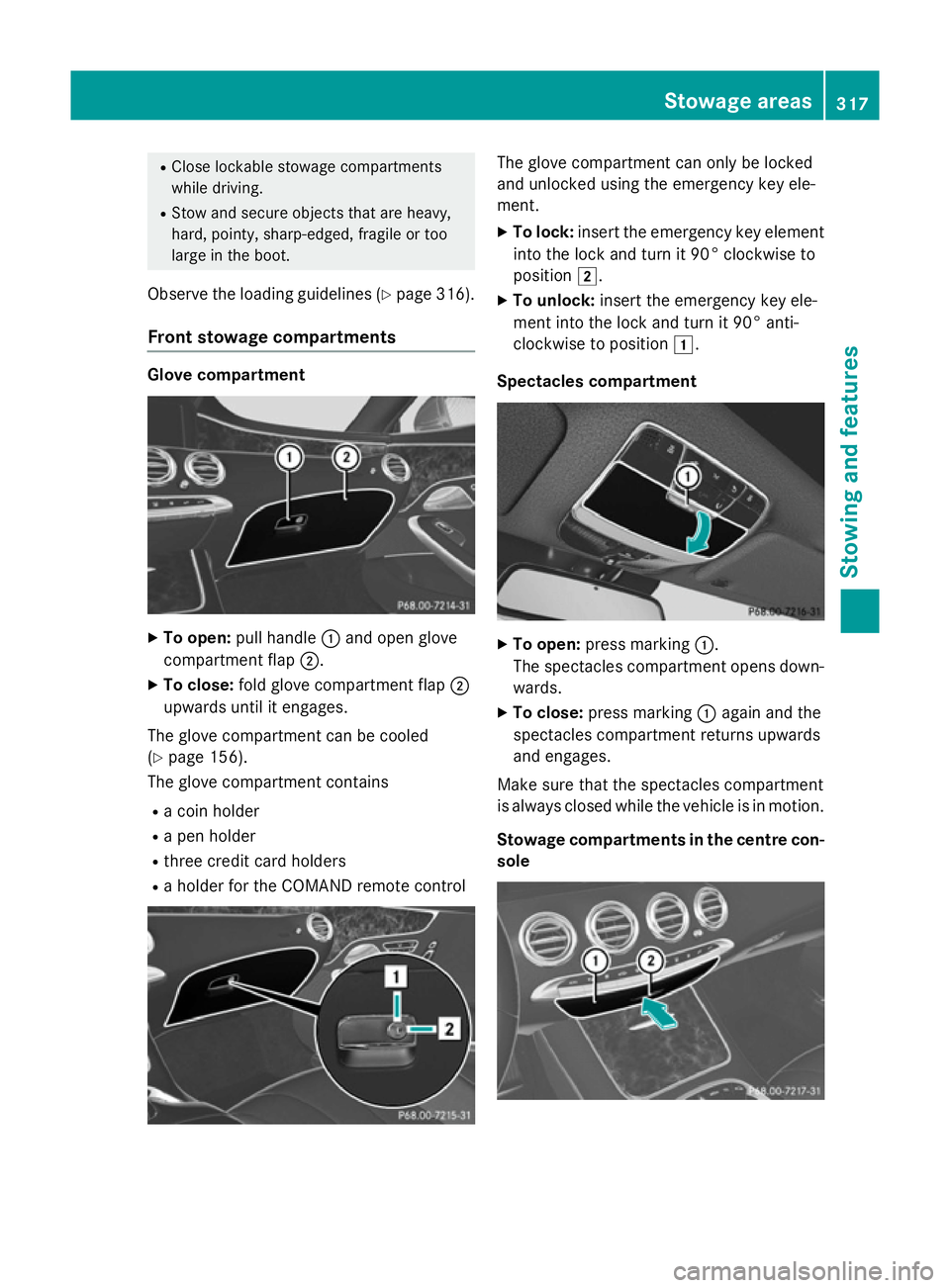
Front stowage compartments Glove compartment
X
To open: pull handle :and open glove
compartment flap ;.
X To close: fold glove compartment flap ;
upwards until it engages.
The glove compartment can be cooled
(Y page 156).
The glove compartment contains
R a coin holder
R a pen holder
R three credit card holders
R a holder for the COMAND remote control The glove compartment can only be locked
and unlocked using the emergency key ele-
ment.
X To lock: insert the emergency key element
into the lock and turn it 90° clockwise to
position 2.
X To unlock: insert the emergency key ele-
ment into the lock and turn it 90° anti-
clockwise to position 1.
Spectacles compartment X
To open: press marking :.
The spectacles compartment opens down- wards.
X To close: press marking :again and the
spectacles compartment returns upwards
and engages.
Make sure that the spectacles compartment
is always closed while the vehicle is in motion.
Stowage compartments in the centre con-
sole Stowage areas
317Stowing and features Z
Page 322 of 417
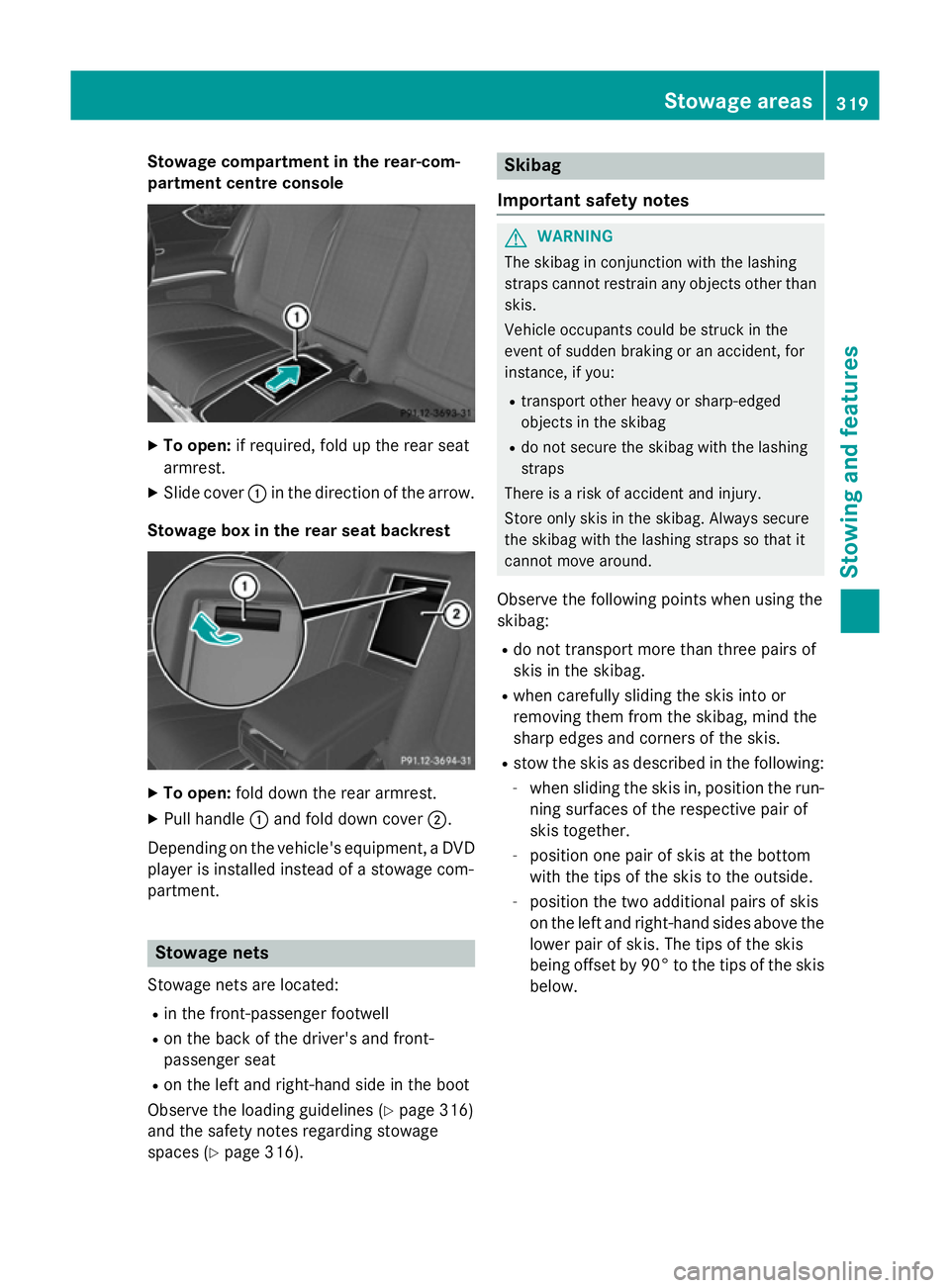
Stowage compartment in the rear-com-
partment centre console X
To open: if required, fold up the rear seat
armrest.
X Slide cover :in the direction of the arrow.
Stowage box in the rear seat backrest X
To open: fold down the rear armrest.
X Pull handle :and fold down cover ;.
Depending on the vehicle's equipment, a DVD
player is installed instead of a stowage com-
partment. Stowage nets
Stowage nets are located: R in the front-passenger footwell
R on the back of the driver's and front-
passenger seat
R on the left and right-hand side in the boot
Observe the loading guidelines (Y page 316)
and the safety notes regarding stowage
spaces (Y page 316). Skibag
Important safety notes G
WARNING
The skibag in conjunction with the lashing
straps cannot restrain any objects other than skis.
Vehicle occupants could be struck in the
event of sudden braking or an accident, for
instance, if you:
R transport other heavy or sharp-edged
objects in the skibag
R do not secure the skibag with the lashing
straps
There is a risk of accident and injury.
Store only skis in the skibag. Always secure
the skibag with the lashing straps so that it
cannot move around.
Observe the following points when using the
skibag:
R do not transport more than three pairs of
skis in the skibag.
R when carefully sliding the skis into or
removing them from the skibag, mind the
sharp edges and corners of the skis.
R stow the skis as described in the following:
- when sliding the skis in, position the run-
ning surfaces of the respective pair of
skis together.
- position one pair of skis at the bottom
with the tips of the skis to the outside.
- position the two additional pairs of skis
on the left and right-hand sides above the
lower pair of skis. The tips of the skis
being offset by 90° to the tips of the skis below. Stowage areas
319Stowing and features Z
Page 323 of 417
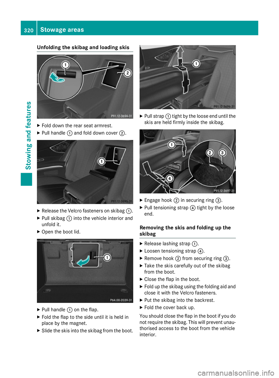
Unfolding the skibag and loading skis
X
Fold down the rear seat armrest.
X Pull handle :and fold down cover ;.X
Release the Velcro fasteners on skibag :.
X Pull skibag :into the vehicle interior and
unfold it.
X Open the boot lid. X
Pull handle :on the flap.
X Fold the flap to the side until it is held in
place by the magnet.
X Slide the skis into the skibag from the boot. X
Pull strap :tight by the loose end until the
skis are held firmly inside the skibag. X
Engage hook ;in securing ring =.
X Pull tensioning strap ?tight by the loose
end.
Removing the skis and folding up the
skibag X
Release lashing strap :.
X Loosen tensioning strap ?.
X Remove hook ;from securing ring =.
X Take the skis carefully out of the skibag
from the boot.
X Close the flap in the boot.
X Fold up the skibag using the folding aid and
close it with the Velcro fasteners.
X Put the skibag into the backrest.
X Fold the cover back up.
You should close the flap in the boot if you do not require the skibag. This will prevent unau-
thorised access to the boot from the vehicle
interior. 320
Stowage areasStowing and features
Page 324 of 417
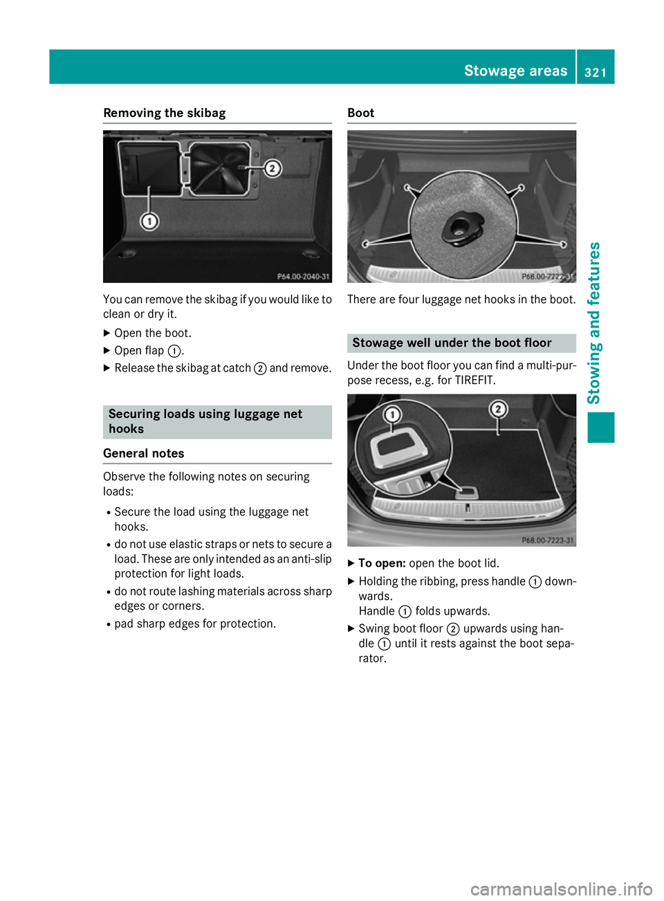
Removing the skibag
You can remove the skibag if you would like to
clean or dry it.
X Open the boot.
X Open flap :.
X Release the skibag at catch ;and remove. Securing loads using luggage net
hooks
General notes Observe the following notes on securing
loads:
R Secure the load using the luggage net
hooks.
R do not use elastic straps or nets to secure a
load. These are only intended as an anti-slip protection for light loads.
R do not route lashing materials across sharp
edges or corners.
R pad sharp edges for protection. Boot There are four luggage net hooks in the boot.
Stowage well under the boot floor
Under the boot floor you can find a multi-pur-
pose recess, e.g. for TIREFIT. X
To open: open the boot lid.
X Holding the ribbing, press handle :down-
wards.
Handle :folds upwards.
X Swing boot floor ;upwards using han-
dle :until it rests against the boot sepa-
rator. Stowage areas
321Stowing and features Z