2015 MERCEDES-BENZ B-Class ELECTRIC lock
[x] Cancel search: lockPage 250 of 338
Always close the cargo compartment floor
before a journey.
! The maximum load capacity of the stow-
age well under the cargo compartment
floor is 55 lbs (25 kg).
There is a stowage area for TIREFIT, the vehi-
cle tool kit, a folding box, etc. underneath the
cargo compartment floor.
Opening/closing the cargo compart-
ment floor X
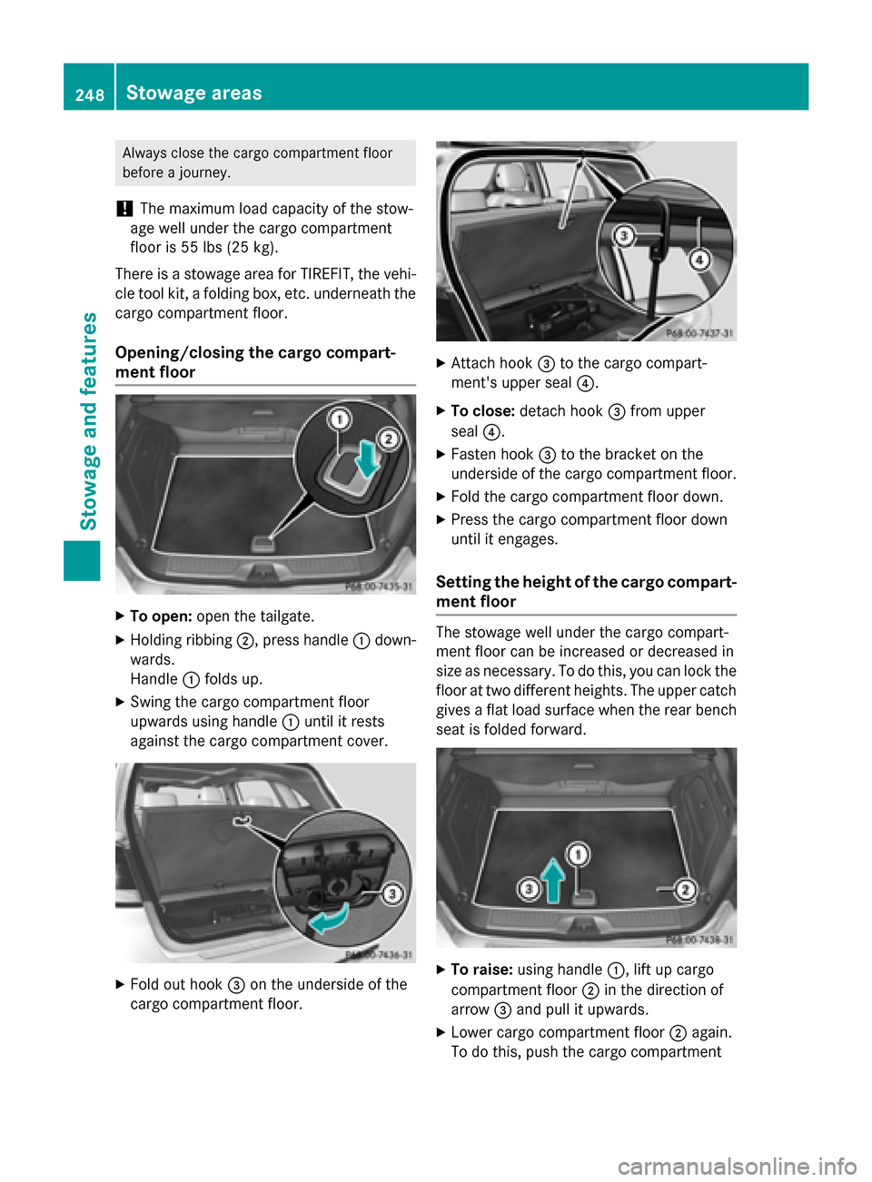
To open: open the tailgate.
X Holding ribbing ;, press handle :down-
wards.
Handle :folds up.
X Swing the cargo compartment floor
upwards using handle :until it rests
against the cargo compartment cover. X
Fold out hook =on the underside of the
cargo compartment floor. X
Attach hook =to the cargo compart-
ment's upper seal ?.
X To close: detach hook =from upper
seal ?.
X Fasten hook =to the bracket on the
underside of the cargo compartment floor.
X Fold the cargo compartment floor down.
X Press the cargo compartment floor down
until it engages.
Setting the height of the cargo compart- ment floor The stowage well under the cargo compart-
ment floor can be increased or decreased in
size as necessary. To do this, you can lock the
floor at two different heights. The upper catch gives a flat load surface when the rear benchseat is folded forward. X
To raise: using handle :, lift up cargo
compartment floor ;in the direction of
arrow =and pull it upwards.
X Lower cargo compartment floor ;again.
To do this, push the cargo compartment 248
Stowage areasSto
wage an d features
Page 252 of 338
There is a risk of injury, particularly in the
event of sudden braking or a sudden change
in direction.
R Always stow objects so that they cannot be
thrown around in such situations.
R Always make sure that objects do not pro-
trude from stowage spaces, parcel nets or
stowage nets.
R Close the lockable stowage spaces while
driving.
R Stow and secure objects that are heavy,
hard, pointy, sharp-edged, fragile or too
large in the cargo compartment.
! Only use the cup holders for containers of
the right size and which have lids. The
drinks could otherwise spill.
Observe the loading guidelines (Y page 240).
The stowage compartments in the doors pro-
vide space for bottles:
R front: capacity up to 51 fl. oz. (1.5 l)
R rear: capacity up to 17 fl. oz. (0.5 l)
Cup holder in the front-compartment
center console The cup holder and the rubber mat under-
neath can be removed for cleaning. Clean
them with clean, lukewarm water only.
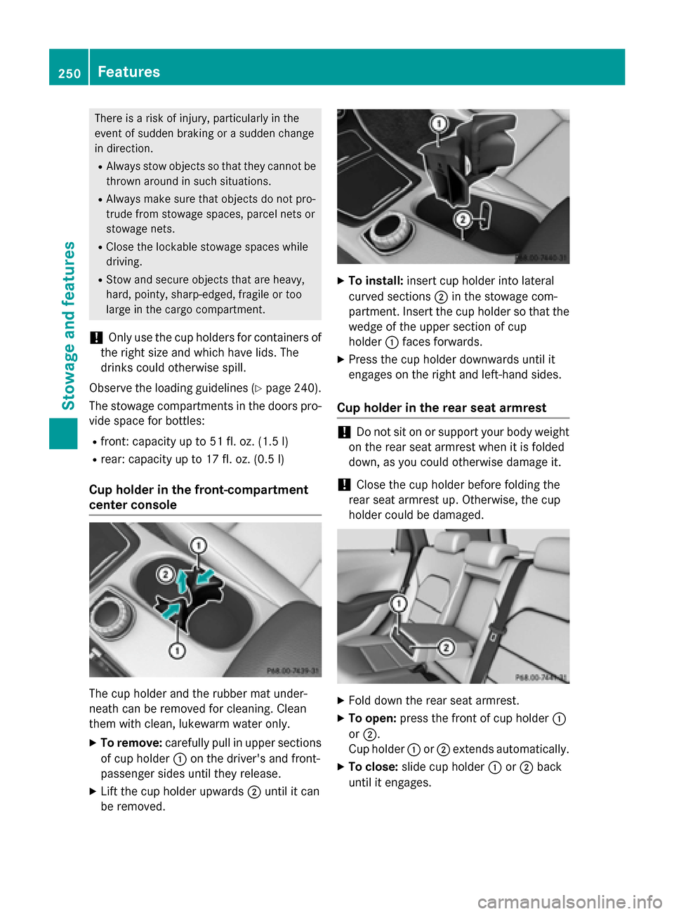
X To remove: carefully pull in upper sections
of cup holder :on the driver's and front-
passenger sides until they release.
X Lift the cup holder upwards ;until it can
be removed. X
To install: insert cup holder into lateral
curved sections ;in the stowage com-
partment. Insert the cup holder so that the wedge of the upper section of cup
holder :faces forwards.
X Press the cup holder downwards until it
engages on the right and left-hand sides.
Cup holder in the rear seat armrest !
Do not sit on or support your body weight
on the rear seat armrest when it is folded
down, as you could otherwise damage it.
! Close the cup holder before folding the
rear seat armrest up. Otherwise, the cup
holder could be damaged. X
Fold down the rear seat armrest.
X To open: press the front of cup holder :
or ;.
Cup holder :or; extends automatically.
X To close: slide cup holder :or; back
until it engages. 250
FeaturesStowage and features
Page 254 of 338
Cigarette lighter
G
WARNING
You can burn yourself if you touch the hot
heating element or the socket of the cigarette lighter.
In addition, flammable materials can ignite if:
R the hot cigarette lighter falls
R a child holds the hot cigarette lighter to
objects, for example
There is a risk of fire and injury.
Always hold the cigarette lighter by the knob.
Always make sure that the cigarette lighter is
out of reach of children. Never leave children unsupervised in the vehicle.
Your attention must always be focused on the traffic conditions. Only use the cigarette
lighter when road and traffic conditions per-
mit. X
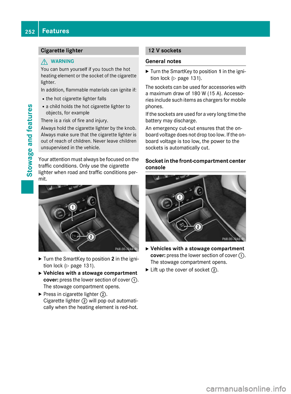
Turn the SmartKey to position 2in the igni-
tion lock (Y page 131).
X Vehicles with a stowage compartment
cover: press the lower section of cover :.
The stowage compartment opens.
X Press in cigarette lighter ;.
Cigarette lighter ;will pop out automati-
cally when the heating element is red-hot. 12 V sockets
General notes X
Turn the SmartKey to position 1in the igni-
tion lock (Y page 131).
The sockets can be used for accessories with a maximum draw of 180 W (15A). Accesso-
ries include such items as chargers for mobile
phones.
If the sockets are used for a very long time the battery may discharge.
An emergency cut-out ensures that the on-
board voltage does not drop too low. If the on-
board voltage is too low, the power to the
sockets is automatically cut.
Socket in the front-co mpartment center
console X
Vehicles with a stowage compartment
cover: press the lower section of cover :.
The stowage compartment opens.
X Lift up the cover of socket ;.252
FeaturesSto
wage an d features
Page 260 of 338
Search & Send
General notes
To use "Search & Send", your vehicle must be
equipped with mbrace and a navigation sys-
tem. Additionally, an mbrace service sub-
scription must be completed.
"Search & Send" is a destination entry ser-
vice. A destination address which is found on
Google Maps ®
can be transferred via mbrace
directly to your vehicle's navigation system.
Specifying and sending the destination
address
X Go to the website http://
maps.google.com and enter a destination
address into the entry field.
X To send the destination address to the
e-mail address of your mbrace account:
click on the corresponding button on the
website.
Example:
If you select 'Send to vehicle' and then
'Mercedes-Benz', the destination address
will be sent to your vehicle.
X When the "Send" dialog window appears:
Enter the e-mail address you specified
when setting up your mbrace account into
the corresponding field.
X Click "Send".
Information on specific commands such as
"Address entry" or "Send" can be found on the website.
Calling up a transmitted destination
address
X Turn the SmartKey to position 2in the igni-
tion lock (Y page 131).
The transmitted destination address is loa- ded into the vehicle's navigation system. A display message appears, asking
whether navigation should be started.
X Select Yes
Yes by turning cVdor sliding XVY
the controller and confirm with W.
The system calculates the route and sub-
sequently starts the route guidance with
the address entered.
If you select No Nothe address can be stored in
the address book.
If you have sent more than one destination address, each individual destination must
be confirmed separately.
Destination addresses are loaded in the same
order as the order in which they were sent.
If you own multiple Mercedes-Benz vehicles
with mbrace and activated mbrace accounts:
If multiple vehicles are registered under the
same e-mail address, the destination will be
sent to all the vehicles.
Vehicle remote opening You can use the vehicle remote opening if you
have unintentionally locked your vehicle and
a replacement SmartKey is not available.
The vehicle can be opened by the Mercedes-
Benz Customer Assistance Center.
The vehicle can be immediately opened
remotely within four days of the ignition being turned off. After this time, the remote unlock-
ing may be delayed by 15 to 60 minutes. After
30 days, the vehicle can no longer be opened remotely.
The vehicle remote unlocking feature is avail-
able if the relevant mobile phone network is
available and a data connection is possible.
X Contact the following service hotlines:
Mercedes-Benz Customer Assistance Cen- ter at 1-800-FOR-MERCedes
(1-800-367-6372) or 1-866-990-9007
You will be asked for your password.
X Return to your vehicle at the time agreed
upon with the Mercedes-Benz Customer
Assistance Center. 258
FeaturesStowage and features
Page 261 of 338

Alternatively, the vehicle can be opened via:
R the Internet, under the "Owners Online"
section
R the telephone application (e .g. for iPhone ®
,
Android)
To do this, you will need your identification
number and password.
Vehicle remote closing The vehicle remote-closing feature can be
used when you have forgotten to lock the
vehicle and you are no longer nearby.
The vehicle can then be locked by the
Mercedes-Benz Customer Assistance Center.
The vehicle can be immediately remotely
locked within four days of the ignition being
turned off. After this time, remote closing may be delayed by 15 to 60 minutes. After 30 days
the vehicle can no longer be locked remotely.
The vehicle remote closing feature is availa-
ble if the relevant mobile phone network is
available and a data connection is possible.
X Contact the following service hotlines:
Mercedes-Benz Customer Assistance Cen- ter at 1-800-FOR-MERCedes
(1-800-367-6372) or 1-866-990-9007
You will be asked for your password.
The next time you are inside the vehicle and
you switch on the ignition, the Doors Doors
Locked Remotely
Locked Remotely message appears in the
multifunction display.
Alternatively, the vehicle can be locked via:
R the Internet, under the "Owners Online"
section
R the telephone application (e .g. for iPhone ®
,
Android)
To do this, you will need your identification
number and password. Stolen vehicle recovery service If your vehicle has been stolen:
X Notify the police.
The police will issue a numbered incident
report.
X This number will be forwarded to the
Mercedes-Benz Customer Assistance Cen-
ter together with your PIN.
The Mercedes-Benz Customer Assistance
Center then tries to locate the system. The Mercedes-Benz Customer Assistance Cen-ter contacts you and the local law enforce-
ment agency if the vehicle is located.
However, only the law enforcement agency is informed of the location of the vehicle.
If the anti-theft alarm system is activated for
longer than 30 seconds, the Mercedes-Benz
Customer Assistance Center is automatically
notified.
Vehicle Health Check With the Vehicle Health Check, the Customer
Assistance Center can provide improved sup-
port for problems with your vehicle. During an existing call, vehicle data is transferred to the
Customer Assistance Center.
The customer service representative can use
the received data to decide what kind of
assistance is required. You are then, for
example, guided to the nearest authorized
Mercedes-Benz Center or a recovery vehicle
is called.
If vehicle data needs to be transferred during an MB Info call or a Roadside Assistance call,this is initiated by the Customer Assistance
Center.
The Roadside Assistance Connected Roadside Assistance Connected
message appears in the display. If the Vehicle
Health Check can be started, the Request
Request
for Vehicle Diagnostics Received
for Vehicle Diagnostics Received
Start vehicle diagnostics? Start vehicle diagnostics? message
appears in the display. Features
259Stowage and features Z
Page 262 of 338
X
Press the Yes
Yesbutton to confirm the mes-
sage.
X When the Vehicle Diagnostics
Vehicle Diagnostics
Please Start Ignition
Please Start Ignition message
appears: turn the SmartKey to position 2in
the ignition lock (Y page 131).
X If the Please follow the instruc‐
Please follow the instruc‐
tions received by phone and move
tions received by phone and move
your vehicle to a safe position. your vehicle to a safe position.
message appears: please follow the
instructions received by phone and move
your vehicle to a safe position.
The message in the display disappears.
The vehicle operating state check begins.
During this procedure, you will see the
Vehicle Vehicle Diagnostics
Diagnostics Active
Activemessage.
If you select Cancel
Cancel, the Vehicle Health
Check is canceled completely.
When the check is complete, the Sending
Sending
vehicle diagnostics data. (Voice
vehicle diagnostics data. (Voice
connection may be interrupted dur‐ connection may be interrupted dur‐
ing
ing data
data transfer)
transfer) message appears. The
vehicle data can now be sent.
X Press the OK
OK button to confirm the mes-
sage.
The voice connection with the Customer
Assistance Center is terminated.
The Vehicle Diagnostics: Transfer‐
Vehicle Diagnostics: Transfer‐
ring Data...
ring Data... message appears.
The vehicle data is sent to the Customer
Assistance Center.
Depending on what the customer service rep-
resentative agreed with you, the voice con-
nection is re-established after the transfer is
complete. If necessary, you will be contacted at a later time by another means, e.g. by e-
mail or phone.
Another function of the Vehicle Health Check is the transfer of service data to the Customer
Assistance Center. If a service is due, the dis-
play shows a message to this effect together with information about any special offers at
your workshop.
This information can also be called up under
"Owners Online" at http://www.mbusa.com. Information on the data stored in the vehicle
(Y
page 26).
Information on Roadside Assistance
(Y page 21).
Downloading routes Downloading routes allows you to transfer
and save predefined routes in the navigation
system.
A route can be prepared and sent by either a customer service representative or under
"Owners Online" at http://www.mbusa.com.
Each route can include up to four way points. Once a route has been received by the navi-
gation system, you will see the The The
name> external
external route
routehas
hasbeen
been saved
saved
to "Previous Destinations". Would
to "Previous Destinations". Would
you you like
like to
tostart
start navigation?
navigation? message
on the COMAND/Audio 20 display.
The route is saved.
X To start route guidance: selectYes
Yes.
An overview of the route is shown in the
display.
If you select No Nothe saved route can be
called up later in the navigation menu.
X Select Start Start.
Route guidance starts.
Downloaded and saved routes can be called
up again.
You can find further information in the sepa-
rate COMAND/Audio 20 operating instruc-
tions.
Speed alert You can define the upper speed limit, which
must not be exceeded by the vehicle.
If this selected speed is exceeded by the vehi-
cle, a message will be sent to the Customer
Assistance Center. The Customer Assistance Center then forwards this information to you.
You can select the way in which you receive
this information beforehand. Possible options include text message, e-mail or an automated
call. 260
FeaturesStowage and features
Page 264 of 338
When using the integrated garage door
opener, always make sure that nobody is
within the range of movement of the garage
door.
G
WARNING
Combustion engines emit poisonous exhaust
gases such as carbon monoxide. Inhaling
these exhaust gases leads to poisoning. There is a risk of fatal injury. Therefore never leave
the engine running in enclosed spaces with-
out sufficient ventilation.
Programming Programming buttons
Pay attention to the "Important safety notes"
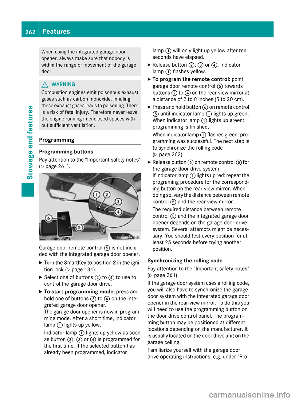
(Y page 261). Garage door remote control
Ais not inclu-
ded with the integrated garage door opener.
X Turn the SmartKey to position 2in the igni-
tion lock (Y page 131).
X Select one of buttons ;to? to use to
control the garage door drive.
X To start programming mode: press and
hold one of buttons ;to? on the inte-
grated garage door opener.
The garage door opener is now in program-
ming mode. After a short time, indicator
lamp :lights up yellow.
Indicator lamp :lights up yellow as soon
as button ;,=or? is programmed for
the first time. If the selected button has
already been programmed, indicator lamp
:will only light up yellow after ten
seconds have elapsed.
X Release button ;,=or?. Indicator
lamp :flashes yellow.
X To program the remote control: point
garage door remote control Atowards
buttons ;to? on the rear-view mirror at
a distance of 2 to 8 inches (5 to 20 cm).
X Press and hold button Bon remote control
A until indicator lamp :lights up green.
When indicator lamp :lights up green:
programming is finished.
When indicator lamp :flashes green: pro-
gramming was successful. The next step is to synchronize the rolling code
(Y page 262).
X Release button Bon remote control Afor
the garage door drive system.
If indicator lamp :lights up red: repeat the
programing procedure for the correspond-
ing button on the rear-view mirror. When
doing so, vary the distance between remote control Aand the rear-view mirror.
The required distance between remote
control Aand the integrated garage door
opener depends on the garage door drive
system. Several attempts might be neces-
sary. You should test every position for at
least 25 seconds before trying another
position.
Synchronizing the rolling code
Pay attention to the "Important safety notes"
(Y page 261).
If the garage door system uses a rolling code,
you will also have to synchronize the garage
door system with the integrated garage door
opener in the rear-view mirror. To do this you
will need to use the programming button on
the door drive control panel. The program-
ming button may be positioned at different
locations depending on the manufacturer. It
is usually located on the door drive unit on the garage ceiling.
Familiarize yourself with the garage door
drive operating instructions, e.g. under "Pro- 262
FeaturesStowage and features
Page 265 of 338
gramming of additional remote controls",
before carrying out the following steps.
Your vehicle must be within reach of the
garage door or gate opener drive. Make sure
that neither your vehicle nor any persons/
objects are present within the sweep of the
door or gate.
X Turn the SmartKey to position 2in the igni-
tion lock (Y page 131).
X Get out of the vehicle.
X Press the programming button on the door
drive unit.
Usually, you now have 30 seconds to ini-
tiate the next step.
X Get into the vehicle.
X Press previously programmed button ;,
= or? on the integrated garage door
opener until the door closes.
The rolling code synchronization is then
complete.
Notes on programming the remote con-
trol
Canadian radio frequency laws require a
"break" (or interruption) of the transmission
signals after broadcasting for a few seconds. Therefore, these signals may not last long
enough for the integrated garage door
opener. The signal is not recognized during
programming. Comparable with Canadian
law, some U.S. garage door openers also fea-
ture a "break".
Proceed as follows:
R if you live in Canada
R if you have difficulties programming the
garage door opener (regardless of where
you live) when using the programming
steps
X Press and hold one of buttons ;to? on
the integrated garage door opener.
After a short time, indicator lamp :lights
up yellow.
X Release the button.
Indicator lamp :flashes yellow. X
Press button Bof garage door remote
control Afor two seconds, then release it
for two seconds.
X Press button Bagain for two seconds.
X Repeat this sequence on button Bof
remote control Auntil indicator lamp :
lights up green.
When indicator lamp :lights up green:
programming is finished.
When indicator lamp :flashes green: pro-
gramming was successful. The next step is to synchronize the rolling code.
X Release button Bof remote control Aof
the garage door drive.
If indicator lamp :lights up red: repeat the
programming process for the correspond-
ing button on the rear-view mirror. When
doing so, vary the distance between remote
control Aand the rear-view mirror.
The required distance between remote
control Aand the integrated garage door
opener depends on the garage door drive
system. Several attempts might be neces-
sary. You should test every position for at
least 25 seconds before trying another
position.
Problems when programming
If you are experiencing problems programing
the integrated garage door opener on the
rear-view mirror, take note of the following
instructions:
R Check the transmitter frequency used by
garage door drive remote control Aand
whether it is supported. The transmitter
frequency can usually be found on the back
of the garage door drive remote control.
The integrated garage door opener is com-
patible with devices that have units which
operate in the frequency range of 280 to
433 MHz.
R Replace the batteries in garage door
remote control A. This increases the like-
lihood that garage door remote control A
will transmit a strong and precise signal to the integrated garage door opener. Features
263Stowage and features Z