2015 MERCEDES-BENZ B-Class ELECTRIC fuel
[x] Cancel search: fuelPage 28 of 338
1-888-327-4236(TTY: 1-800-424-9153); go
to http://www.safercar.gov ; or write to:
Administrator, NHTSA, 400 Seventh Street,
SW., Washington, DC 20590.
You can also obtain other information about
motor vehicle safety from
http://www.safercar.gov Limited Warranty
! Follow the instructions in this manual
about the proper operation of your vehicle
as well as about possible vehicle damage.
Damage to your vehicle that arises from
culpable contraventions against these
instructions is not covered either by the
Mercedes-Benz Limited Warranty or by the New or Used-Vehicle Warranty. QR codes for the rescue card
The QR codes are secured in the fuel filler flap
and on the opposite side on the B-pillar. In the event of an accident, rescue services can use
the QR code to quickly find the appropriate
rescue card for your vehicle. The current res- cue card contains the most important infor-
mation about your vehicle in a compact form, e.g. the routing of the electric cables.
You can find more information under https://
portal.aftersales.i.daimler.com/public/
content/asportal/en/communication/
informationen_fuer/QRCode.html. Data stored in the vehicle
Data recording
This vehicle is capable of recording diagnostic information relating to vehicle operation, mal-functions, and user settings. This may include
information about the performance or status
of various systems, including but not limited
to, engine, throttle, steering or brake sys-
tems, that is stored and can be read out with
suitable devices, particularly when the vehi- cle is serviced. The data obtained is used to
properly diagnose and service your vehicle or
to further optimize and develop vehicle func-
tions. COMAND/mbrace
If the vehicle is equipped with COMAND or
mbrace, additional data about the vehicle’s
operation, the use of the vehicle in certain
situations, and the location of the vehicle may be compiled through COMAND or the mbrace
system.
For additional information please refer to the
COMAND User Manual and/or the mbrace
Terms and Conditions. Event data recorders
This vehicle is equipped with an event data
recorder (EDR). The main purpose of an EDR
is to record data that will assist in under-
standing how a vehicle’s systems performed
in certain crash or near crash-like situations,
such as during air bag deployment or when
hitting a road obstacle. The EDR is designed
to record data related to vehicle dynamics
and safety systems for a short period of time, typically 30 seconds or less.
The EDR in this vehicle is designed to record
such data as:
R how various systems in your vehicle are
operating
R whether or not the driver and passenger
seat belts are fastened
R how far (if at all) the driver is depressing the
accelerator and/or brake pedal and
R how fast the vehicle is traveling
This data can help provide a better under-
standing of the circumstances in which
crashes and injuries occur. NOTE: EDR data is recorded by your vehicle only if a non-trivial
crash situation occurs; no data is recorded by
the EDR under normal driving conditions and no personal data (e.g., name, gender, age, 26
Introduction
Page 160 of 338
The ECO display does not indicate the actual
fuel consumption. A fixed percentage count
in the ECO display does not indicate a fixed
consumption.
Apart from driving style, consumption is
dependent on many factors such as, e.g.:
R load
R tire pressure
R cold start
R choice of route
R electrical consumers switched on
These factors are not included in the ECO dis-
play.
The evaluation of your driving style is carried
out using the following three categories:
R Acceleration
Acceleration (evaluation of all accelera-
tion processes):
- The bar fills up: moderate acceleration,
especially at higher speeds
- The bar empties: sporty acceleration
R Constant
Constant (assessment of driving behavior
at all times)
- The bar fills up: constant speed and
avoidance of unnecessary acceleration
and deceleration
- The bar empties: fluctuations in speed
R Coasting
Coasting (assessment of all deceleration
processes)
- The bar fills up: anticipatory driving,
keeping your distance and early release
of the accelerator. The vehicle can coast
without use of the brakes.
- The bar empties: frequent braking
To achieve a higher value in the categories
Acceleration Acceleration andConstant
Constant, drive the vehi-
cle in drive program E+orE.
On long journeys at a constant speed, e.g. on
the highway, only the bar for Constant
Constantwill
change.
The ECO display summarizes the driving char- acteristics from the start of the journey to its completion. For this reason, the bars change
dynamically at the beginning of the journey.
On longer journeys, there are fewer changes. For more dynamic changes, carry out a man-
ual reset.
For further information on the ECO display,
see (Y page 187). Braking
Important safety notes G
WARNING
If you increase the recuperation level on slip- pery road surfaces, the drive wheels may lose
their traction. There is an increased danger of skidding and accidents.
Do not increase the recuperation level on slip-
pery road surfaces.
The braking performance of the electric
motor using recuperative braking is, in some
operating modes, either reduced or not effec- tive:
R when the condition of charge of the high-
voltage battery increases
R if the high-voltage battery is not yet at a
normal operating temperature
R when driving close to the maximum speed
R when the vehicle is almost stationary
R in transmission position N
R during and after ESP stability control
If you do not make an additional effort to
apply the brake yourself, the braking effect
may not be sufficient. If necessary, counter-
act the reduced regenerative braking effect
by applying the brake yourself.
Downhill gradients On long, steep gradients, you must reduce the
load on the brakes by selecting maximum
recuperation. This helps you to avoid over-
heating the brakes and wearing them out
excessively.
Recuperation allows the vehicle to be decel-
erated without placing a load on the braking
system. 158
Driving tipsDriving and parking
Page 190 of 338
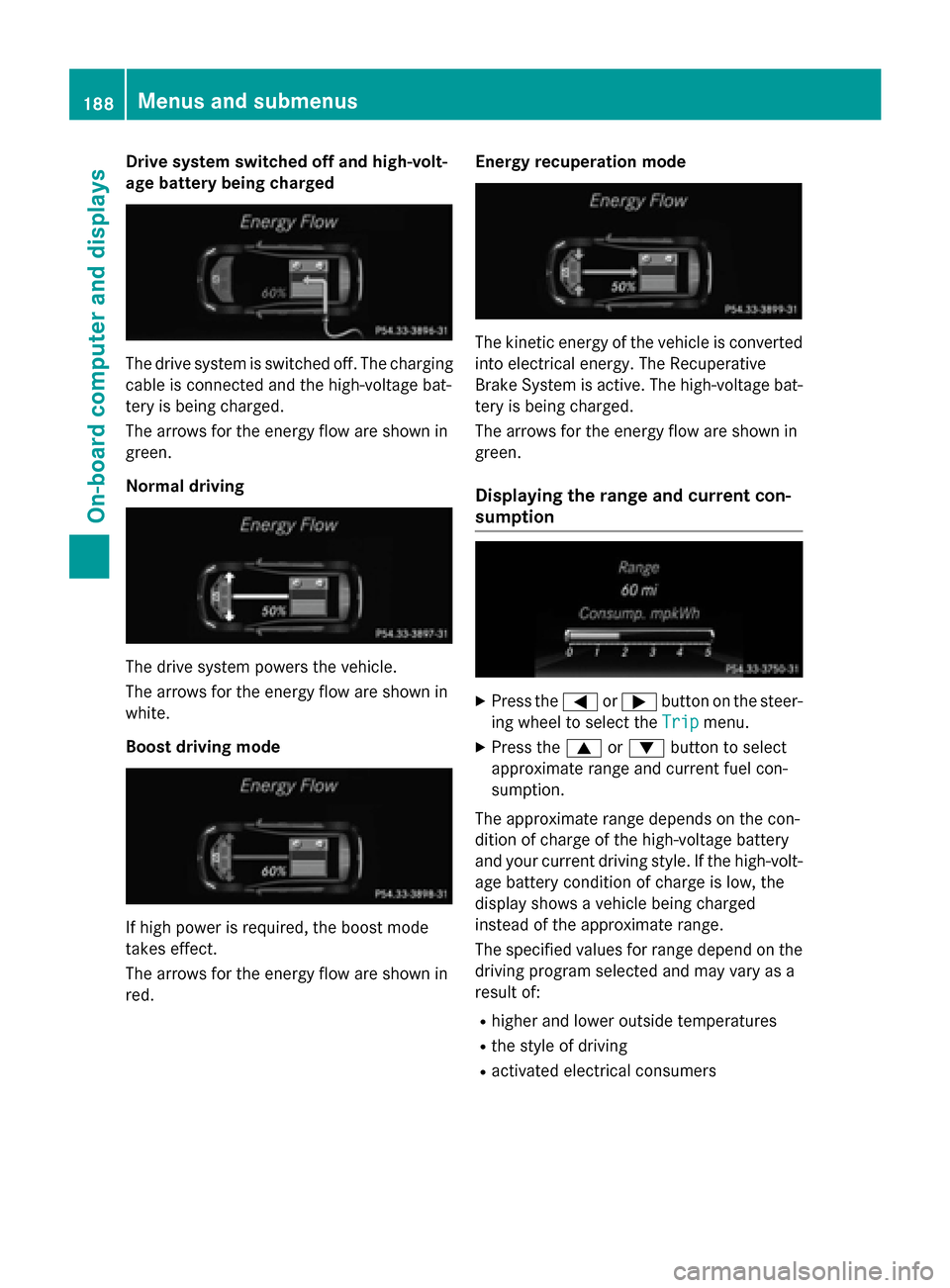
Drive system switched off and high-volt-
age battery being charged The drive system is switched off. The charging
cable is connected and the high-voltage bat-
tery is being charged.
The arrows for the energy flow are shown in
green.
Normal driving The drive system powers the vehicle.
The arrows for the energy flow are shown in
white.
Boost driving mode If high power is required, the boost mode
takes effect.
The arrows for the energy flow are shown in
red. Energy recuperation mode The kinetic energy of the vehicle is converted
into electrical energy. The Recuperative
Brake System is active. The high-voltage bat-
tery is being charged.
The arrows for the energy flow are shown in
green.
Displaying the range and current con-
sumption X
Press the =or; button on the steer-
ing wheel to select the Trip Tripmenu.
X Press the 9or: button to select
approximate range and current fuel con-
sumption.
The approximate range depends on the con-
dition of charge of the high-voltage battery
and your current driving style. If the high-volt- age battery condition of charge is low, the
display shows a vehicle being charged
instead of the approximate range.
The specified values for range depend on the
driving program selected and may vary as a
result of:
R higher and lower outside temperatures
R the style of driving
R activated electrical consumers 188
Menus and sub
menusOn-board computer and displays
Page 275 of 338
wiping noises caused by residue on the wind-
shield.
Washing by hand In some countries, washing by hand is only
allowed at specially equipped washing bays.
Observe the legal requirements in each coun-
try.
X Do not use hot water and do not wash the
vehicle in direct sunlight.
X Use a soft sponge to clean.
X Use a mild cleaning agent, such as a car
shampoo approved by Mercedes-Benz.
X Thoroughly hose down the vehicle with a
gentle jet of water.
X Do not point the water jet directly towards
the air inlet.
X Use plenty of water and rinse out the
sponge frequently.
X Rinse the vehicle with clean water and dry
thoroughly with a chamois.
X Do not let the cleaning agent dry on the
paintwork.
Carefully remove all deposits of road salt as
soon as possible when driving in winter.
Power washers G
WARNING
The water jet from a circular jet nozzle (dirt
blasters) can cause invisible exterior damage to the tires or chassis components. Compo-
nents damaged in this way may fail unexpect-edly. There is a risk of an accident.
Do not use power washers with circular jet
nozzles to clean the vehicle. Have damaged
tires or chassis components replaced imme-
diately.
! Always maintain a distance of at least
11.8 in (30 cm) between the vehicle and the
power washer nozzle. Information about
the correct distance is available from the
equipment manufacturer. Move the power washer nozzle around
when cleaning your vehicle.
Do not aim directly at any of the following:
R tires
R door gaps, roof gaps, joints, etc.
R electrical components
R battery
R connectors
R lights
R seals
R trim
R ventilation slots
Damaged seals or electrical components
can lead to leaks or failures.
Cleaning the paintwork !
Do not affix:
R stickers
R films
R magnetic plates or similar items
to painted surfaces. You could otherwise
damage the paintwork.
Scratches, corrosive deposits, areas affected by corrosion and damage caused by inade-
quate care cannot always be completely
repaired. In such cases, visit a qualified spe-
cialist workshop.
X Remove dirt immediately, where possible,
while avoiding rubbing too hard.
X Soak insect remains with insect remover
and rinse off the treated areas afterwards.
X Soak bird droppings with water and rinse
off the treated areas afterwards.
X Remove coolant, brake fluid, tree resin,
oils, fuels and greases by rubbing gently
with a cloth soaked in petroleum ether or
lighter fluid.
X Use tar remover to remove tar stains.
X Use silicone remover to remove wax.
If water no longer forms "beads" on the paint
surface, use the paint care products recom-
mended and approved by Mercedes-Benz. Care
273Maintenance and care Z
Page 309 of 338
Checking tire pressures manually
To determine and set the correct tire pres-
sure, proceed as follows:
X Remove the valve cap of the tire that is to
be checked.
X Press the tire pressure gauge securely onto
the valve.
X Read the tire pressure and compare it to
the recommended value on the Tire and
Loading Information placard or the tire
pressure table (Y page 303).
X If the tire pressure is too low, increase the
tire pressure to the recommended value.
X If the tire pressure is too high, release air.
To do so, press down the metal pin in the
valve, using the tip of a pen for example.
Then check the tire pressure again using
the tire pressure checker.
X Screw the valve cap onto the valve.
X Repeat these steps for the other tires. Tire pressure monitor
General notes If a tire pressure monitor is installed, the vehi-
cle's wheels have sensors that monitor the
tire pressures in all four tires. The tire pres-
sure monitor warns you if the pressure drops
in one or more of the tires. The tire pressure
monitor only functions if the corresponding
sensors are installed in all wheels.
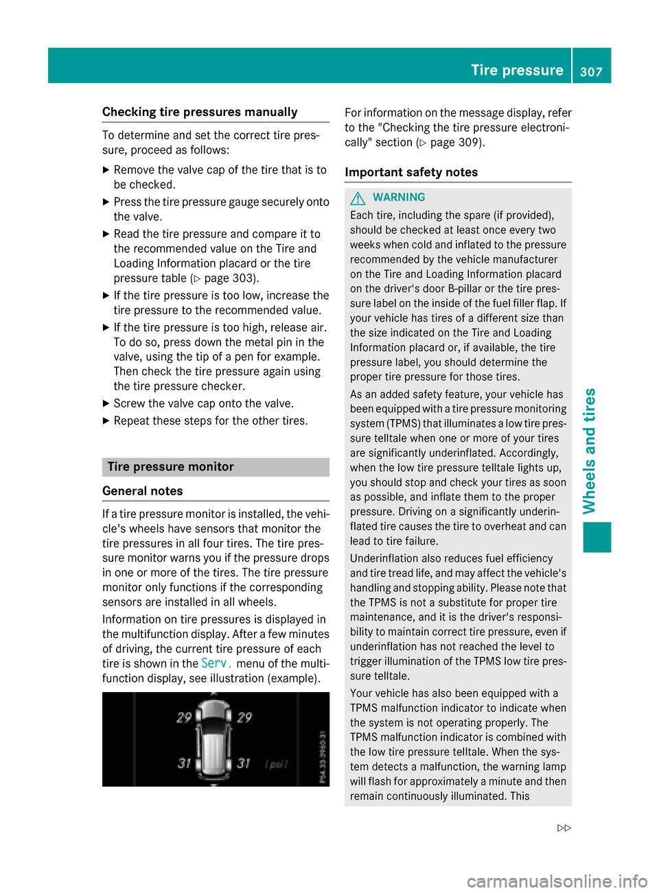
Information on tire pressures is displayed in
the multifunction display. After a few minutes of driving, the current tire pressure of each
tire is shown in the Serv. Serv.menu of the multi-
function display, see illustration (example). For information on the message display, refer
to the "Checking the tire pressure electroni-
cally" section (Y page 309).
Important safety notes G
WARNING
Each tire, including the spare (if provided),
should be checked at least once every two
weeks when cold and inflated to the pressure recommended by the vehicle manufacturer
on the Tire and Loading Information placard
on the driver's door B-pillar or the tire pres-
sure label on the inside of the fuel filler flap. If
your vehicle has tires of a different size than
the size indicated on the Tire and Loading
Information placard or, if available, the tire
pressure label, you should determine the
proper tire pressure for those tires.
As an added safety feature, your vehicle has
been equipped with a tire pressure monitoring system (TPMS) that illuminates a low tire pres-
sure telltale when one or more of your tires
are significantly underinflated. Accordingly,
when the low tire pressure telltale lights up,
you should stop and check your tires as soon
as possible, and inflate them to the proper
pressure. Driving on a significantly underin-
flated tire causes the tire to overheat and can
lead to tire failure.
Underinflation also reduces fuel efficiency
and tire tread life, and may affect the vehicle's handling and stopping ability. Please note that the TPMS is not a substitute for proper tire
maintenance, and it is the driver's responsi-
bility to maintain correct tire pressure, even if
underinflation has not reached the level to
trigger illumination of the TPMS low tire pres-
sure telltale.
Your vehicle has also been equipped with a
TPMS malfunction indicator to indicate when
the system is not operating properly. The
TPMS malfunction indicator is combined with
the low tire pressure telltale. When the sys-
tem detects a malfunction, the warning lamp
will flash for approximately a minute and then remain continuously illuminated. This Tire pressure
307Wheels and tires
Z
Page 312 of 338
pressure will be displayed after
pressure will be displayed after
driving a few minutes
driving a few minutes message.
X Press the :button.
The multifunction display shows the Use
Use
current
current pressures
pressures as
asnew
new reference
reference
values
values message.
If you wish to confirm the restart:
X Press the abutton.
The Tire Press. Monitor Restarted
Tire Press. Monitor Restarted
message appears in the multifunction dis-
play.
After driving for a few minutes, the system checks whether the current tire pressures
are within the specified range. The new tire
pressures are then accepted as reference
values and monitored.
If you wish to cancel the restart:
X Press the %button.
The tire pressure values stored at the last
restart will continue to be monitored.
Radio type approval for the tire pres-
sure monitor Country Radio type approval number
USA FCC ID: MRXMW2433A
FCC ID: MRXGG4
FCC ID: MRXMC34MA4
Canada IC: 2546A-MW2433A
IC: 2546A-GG4
IC: 2546A-MC34MA4
Loading the vehicle
Instruction labels for tires and loads
G
WARNING
Overloaded tires can overheat, causing a
blowout. Overloaded tires can also impair the steering and driving characteristics and lead
to brake failure. There is a risk of accident.
Observe the load rating of the tires. The load
rating must be at least half of the GAWR of your vehicle. Never overload the tires by
exceeding the maximum load.
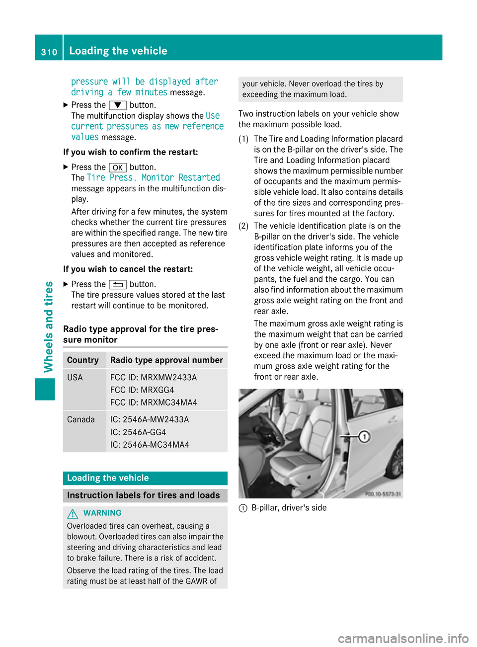
Two instruction labels on your vehicle show
the maximum possible load.
(1) The Tire and Loading Information placard is on the B-pillar on the driver's side. The
Tire and Loading Information placard
shows the maximum permissible number of occupants and the maximum permis-
sible vehicle load. It also contains details
of the tire sizes and corresponding pres-
sures for tires mounted at the factory.
(2) The vehicle identification plate is on the B-pillar on the driver's side. The vehicle
identification plate informs you of the
gross vehicle weight rating. It is made up
of the vehicle weight, all vehicle occu-
pants, the fuel and the cargo. You can
also find information about the maximum gross axle weight rating on the front and
rear axle.
The maximum gross axle weight rating is the maximum weight that can be carried
by one axle (front or rear axle). Never
exceed the maximum load or the maxi-
mum gross axle weight rating for the
front or rear axle. :
B-pillar, driver's side 310
Loading the vehicleWheels and tires
Page 321 of 338
DOT (Department of Transportation)
DOT-marked tires fulfill the requirements of
the U S Department of Transportation.
Normal occupant weight
The number of occupants for which the vehi-
cle is designed multiplied by 68 kilograms
(150 lbs).
Uniform Tire Quality Grading Standards
A uniform standard to grade the quality of
tires with regards to tread quality, tire traction and temperature characteristics. The quality
grading assessment is made by the manufac-
turer following specifications from the U.S.
government. The ratings are molded into the
sidewall of the tire.
Recommended tire pressures
The recommended tire pressure applies to
the tires mounted at the factory.
The Tire and Loading Information placard con- tains the recommended tire pressures for
cold tires on a fully loaded vehicle and for the maximum permissible vehicle speed.
The tire pressure table contains the recom-
mended pressures for cold tires for various
operating conditions, i.e. differing load and
speed conditions.
Increased vehicle weight due to optional
equipment
The combined weight of all standard and
optional equipment available for the vehicle,
regardless of whether it is actually installed
on the vehicle or not.
Rim
This is the part of the wheel on which the tire
is mounted.
GAWR (Gross Axle Weight Rating)
The GAWR is the maximum gross axle weight rating. The actual load on an axle must neverexceed the gross axle weight rating. The
gross axle weight rating can be found on the
vehicle identification plate on the B-pillar on
the driver's side. Speed rating
The speed rating is part of the tire identifica-
tion. It specifies the speed range for which the
tire is approved.
GVW (Gross Vehicle Weight)
The gross vehicle weight includes the weight
of the vehicle including fuel, tools, the spare
wheel, accessories installed, occupants, lug-
gage and the drawbar noseweight, if applica-
ble. The gross vehicle weight must not exceed the gross vehicle weight rating GVWR as
specified on the vehicle identification plate on
the B-pillar on the driver's side.
GVWR (Gross Vehicle Weight Rating)
The GVWR is the maximum permissible gross weight of a fully loaded vehicle (the weight of the vehicle including all accessories, occu-
pants, fuel, luggage and the drawbar nose-
weight, if applicable). The gross vehicle
weight rating is specified on the vehicle iden-
tification plate on the B-pillar on the driver's
side.
Maximum loaded vehicle weight
The maximum weight is the sum of:
R the curb weight of the vehicle
R the weight of the accessories
R the load limit
R the weight of the factory installed optional
equipment
Kilopascal (kPa)
Metric unit for tire pressure. 6.9 kPa corre-
sponds to 1 psi. Another unit for tire pressure is bar. 100 kilopascals (kPa) are the equiva-
lent of 1 bar.
Load index
In addition to the load-bearing index, the load
index may also be imprinted on the sidewall of the tire. This specifies the load-bearing capa- city more precisely. All about wheels and ti
res
319Wheels and tires Z
Page 322 of 338
Curb weight
The weight of a vehicle with standard equip-
ment including the maximum capacity of fuel, oil and coolant. It also includes the air-condi-
tioning system and optional equipment if
these are installed in the vehicle, but does not include passengers or luggage.
Maximum load rating
The maximum load rating is the maximum
permissible weight in kilograms or lbs for
which a tire is approved.
Maximum permissible tire pressure
Maximum permissible tire pressure for one
tire.
Maximum load on one tire
Maximum load on one tire. This is calculated
by dividing the maximum axle load of one axle by two.
PSI (pounds per square inch)
A standard unit of measure for tire pressure.
Aspect ratio
Relationship between tire height and tire
width in percent.
Tire pressure
This is pressure inside the tire applying an
outward force to each square inch of the tire's
surface. The tire pressure is specified in
pounds per square inch (psi), in kilopascal
(kPa) or in bar. The tire pressure should only
be corrected when the tires are cold.
Cold tire pressure
The tires are cold:
R if the vehicle has been parked without
direct sunlight on the tires for at least three
hours and
R if the vehicle has not been driven further
than 1 mile (1.6 km) Tread
The part of the tire that comes into contact
with the road.
Bead
The tire bead ensures that the tire sits
securely on the wheel. There are several steel
wires in the bead to prevent the tire from
coming loose from the wheel rim.
Sidewall
The part of the tire between the tread and the bead.
Weight of optional extras
The combined weight of those optional extras
that weigh more than the replaced standard
parts and more than 2.3 kg (5 lbs). These
optional extras, such as high-performance
brakes, level control, a roof rack or a high-
performance battery, are not included in the
curb weight and the weight of the accesso-
ries.
TIN (Tire Identification Number)
This is a unique identifier which can be used
by a tire manufacturer to identify tires, for
example for a product recall, and thus identify the purchasers. The TIN is made up of the
manufacturer's identity code, tire size, tire
type code and the manufacturing date.
Load bearing index
The load bearing index (also load index) is a
code that contains the maximum load bearing
capacity of a tire.
Traction
Traction is the result of friction between the
tires and the road surface.
Treadwear indicators
Narrow bars (tread wear bars) that are dis-
tributed over the tire tread. If the tire tread is level with the bars, the wear limit of áin
(1.6 mm) has been reached. 320
All about wheels and tiresWheels and tires