2015 MERCEDES-BENZ B-Class ELECTRIC trunk
[x] Cancel search: trunkPage 19 of 338

Installing the towing eye ................ 294
Removing the towing eye ............... 294
Transporting the vehicle ................ 295
With both axles on the ground ....... 294
With front axle raised .....................2 95
With the rear axle raised ................ 295
Towing eye ......................................... 280
Trailer hitch ......................................... 24
Trailer tow hitch .................................. 24
Transmission
DIRECT SELECT lever ..................... 134
Drive program ................................ 137
Driving tips ................................... .137
Engaging the drive position ............ 136
Engaging the park position ............ 135
Holding the vehicle stationary on
uphill gradients .............................. 137
Kickdown ....................................... 137
Overview ........................................ 134
Program selector button ................ 137
Shifting to neutra l.......................... 135
Transmission position display ......... 134
Transmission position display
(DIRECT SELECT lever) ...................... 134
Transmission positions .................... 136
Transporting the vehicle .................. 295
Trim pieces (cleaning instruc-
tions) .................................................. 277
Trip computer (on-board com-
puter) .................................................. 187
Trip odometer
Calling up ....................................... 186
Resetting (on-board computer) ...... 189
Trunk load (maximum) ...................... 334
Turn signals
Changing bulbs (front) ................... 108
Display message ............................ 214
Switching on/of f........................... 102
Type identification plate
see Vehicle identification plate U
Unlocking Emergency unlocking ....................... 80
From inside the vehicle (central
unlocking button) ............................. 80 V
Vanity mirror (in the sun visor) ........ 251
Vehicle
Correct use ...................................... 25
Data acquisition ............................... 26
Display message ............................ 223
Equipment ....................................... 20
Individual settings .......................... 195
Limited Warranty ............................. 26
Loading .......................................... 310
Locking (in an emergency) ............... 81
Locking (SmartKey) .......................... 72
Lowering ........................................ 325
Maintenance .................................... 21
Parking for a long period ................ 156
Raising ........................................... 322
Reporting problems ......................... 25
Securing from rolling away ............ 322
Starting .......................................... 132
Transporting .................................. 295
Unlocking (in an emergency) ........... 80
Unlocking (SmartKey) ...................... 72
Vehicle data ................................... 334
Vehicle data
Roof load (maximum) ..................... 334
Trunk load (maximum) ................... 334
Vehicle dimensions ........................... 334
Vehicle emergency locking ................ 81
Vehicle Homepage
Data protection .............................. 152
Functions ....................................... 153
General information ....................... 152
Internet connection ....................... 153
Vehicle identification number
see VIN
Vehicle identification plate .............. 330
Vehicle tool kit .................................. 280
Ventilation
Setting the vents ........................... 126
Video
Operating the DVD ......................... 191
VIN ...................................................... 330 W
Warning and indicator lamps ABS ................................................ 230 Index
17
Page 76 of 338
X
To deactivate: press the&button on
the SmartKey twice in rapid succession.
The battery check lamp of the SmartKey
(Y page 75) lights up twice briefly and
KEYLESS-GO is deactivated.
X To activate: press any button on the
SmartKey or insert the SmartKey into the
ignition lock.
KEYLESS-GO and all of its associated fea-
tures are available again. KEYLESS-GO start function
Bear in mind that the engine can be started by any of the vehicle occupants if there is a
SmartKey in the vehicle. Changing the settings of the locking
system
You can change the settings of the locking
system. This means that only the driver's door and the charge socket flap are unlocked when the vehicle is unlocked. This is useful if you
frequently travel on your own.
X To change the setting: simultaneously
press the %and& buttons for
approximately 6 seconds until the battery
check lamp (Y page 75) flashes twice.
i If the setting of the locking system is
changed within the signal range of the vehi- cle, pressing the &or% button:
R locks or
R unlocks the vehicle
The SmartKey now functions as follows:
X To unlock the driver's door: press the
% button once.
X To unlock centrally: press the%but-
ton twice.
X To lock centrally: press the&button. The KEYLESS-GO function is changed as fol-
lows:
X To unlock the driver's door: touch the
inner surface of the door handle on the
driver's door.
X To unlock centrally: touch the inner sur-
face of the door handle on the front-
passenger door or the rear door.
X To lock centrally: touch the outer sensor
surface on one of the door handles.
X To restore the factory settings: simulta-
neously press the %and& buttons
for approximately 6 seconds until the bat-
tery check lamp flashes twice
(Y page 75). Mechanical key
General notes If the vehicle can no longer be locked or
unlocked with the SmartKey or KEYLESS-GO, use the mechanical key.
If you use the mechanical key to unlock and
open the driver's door or the trunk lid, the
anti-theft alarm system will be triggered
(Y page 69).
There are several ways to turn off the alarm:
X To turn the alarm off with the SmartKey:
press the %or& button on the
SmartKey.
or X Insert the SmartKey into the ignition lock.
or
X To deactivate the alarm with KEYLESS-
GO: press the Start/Stop button in the igni-
tion lock. The SmartKey must be in the
vehicle.
or X Lock or unlock the vehicle using KEYLESS-
GO. The SmartKey must be outside the
vehicle. 74
SmartKeyOpening and closing
Page 148 of 338
interruption in the power supply. These
functions protect the vehicle. After the
building fuse is switched on again, the
charging process resumes automatically.
Following an interruption in the power sup- ply without tripping of the building's fuse, it
may take up to 15 minutes for charging to
resume automatically.
Switch on the building's fuse again after the
protection device against overvoltage has
been triggered. Otherwise, the charging proc-
ess cannot be continued. The high-voltage
battery will not be charged and you may not
be able to drive the vehicle.
If other devices are protected by the same
protective device, these are switched off as
well when the protective device is triggered.
Ensure that these other devices are still
operational after reactivating the protection
device. Charging the high-voltage battery via
the electrical outlet
Charging cable Important safety notes
! Only use the charging cable to charge the
high-voltage battery. Do not use the charg-
ing cable for other purposes. It may other-
wise be damaged.
The vehicle is supplied with a single-phase
12 A charging cable. Only use the charging
cable included with the vehicle, which has
been approved for vehicle use.
Pay attention to the "Important safety notes"
(Y page 140).
If you use the supplied 12 Acharging cable to
charge a high-voltage battery:
R the charge time increases considerably
R electrical consumption increases consider-
ably
Where possible, charge the high-voltage bat-
tery at a charging station (Y page 149). Onlythen can certified electrical energy consump-
tion levels be reached.
i The charging process can vary depending
on the charging station. Therefore, always
observe the local information.
Stowing the charging cable
The charging cable can be stowed in a bag in the trunk of the vehicle. To do so, the bag
must be secured to the cargo tie-down rings
using the retaining strap provided.
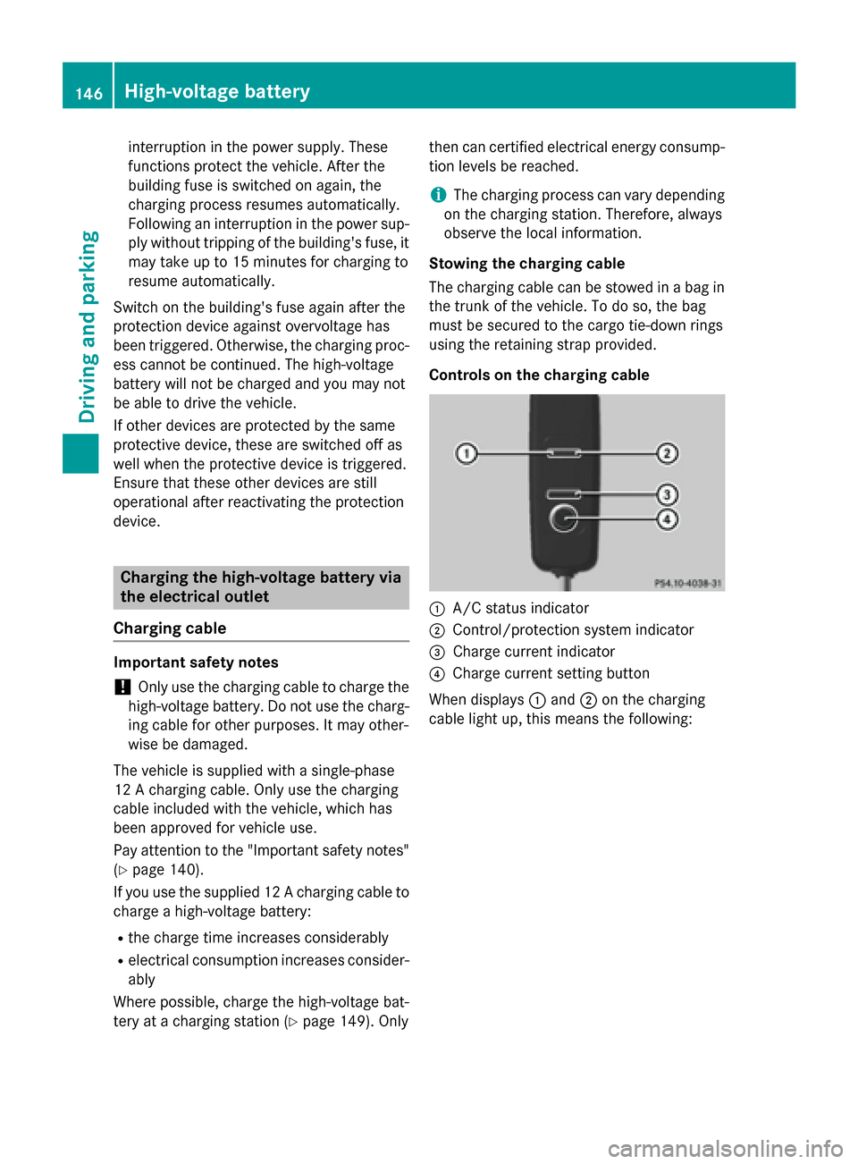
Controls on the charging cable :
A/C status indicator
; Control/protection system indicator
= Charge current indicator
? Charge current setting button
When displays :and ;on the charging
cable light up, this means the following: 146
High-voltage batteryDriving and parking
Page 175 of 338
Under the following circumstances, the rear
view camera will not function, or will function
in a limited manner:
R if the trunk lid is open
R in heavy rain, snow or fog
R at night or in very dark places
R if the camera is exposed to very bright light
R if the area is lit by fluorescent bulbs or LED
lighting (the display may flicker)
R if there is a sudden change in temperature,
e.g. when driving into a heated garage in
winter
R if the camera lens is dirty or obstructed.
Observe the notes on cleaning
(Y page 276)
R if the rear of your vehicle is damaged. In this
event, have the camera position and setting checked at a qualified specialist workshop
The field of vision and other functions of the
rear view camera may be restricted due to
additional accessories on the rear of the vehi-
cle (e.g. license plate holder, bicycle rack).
Activating/deactivating the rear view
camera X
To activate: make sure that the key is in
position 2in the ignition lock.
X Make sure that the Activation by R Activation by R
gear
gear function is selected in Audio 20/
COMAND; see the Digital Operator's Man-
ual.
X Engage reverse gear.
The area behind the vehicle is shown with
guide lines in the Audio 20/COMAND dis-
play.
The image from the rear view camera is
available throughout the maneuvering
process.
To deactivate: the rear view camera deacti-
vates if you shift the transmission to Por after
driving forwards a short distance. Displays in the Audio 20/COMAND dis-
play The rear view camera may show a distorted
view of obstacles, show them incorrectly or
not at all. The rear view camera does not show
objects in the following positions:
R very close to the rear bumper
R under the rear bumper
R in the area immediately above the tailgate
handle
! Objects not at ground level may appear to
be further away than they actually are, e.g.:
R the bumper of a parked vehicle
R the drawbar of a trailer
R the ball coupling of a trailer tow hitch
R the rear section of an HGV
R a slanted post
Use the guidelines only for orientation.
Approach objects no further than the bot-
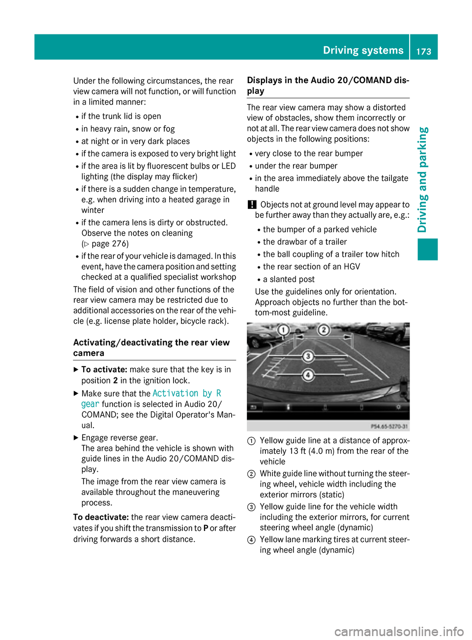
tom-most guideline. :
Yellow guide line at a distance of approx-
imately 13 ft (4.0 m) from the rear of the
vehicle
; White guide line without turning the steer-
ing wheel, vehicle width including the
exterior mirrors (static)
= Yellow guide line for the vehicle width
including the exterior mirrors, for current
steering wheel angle (dynamic)
? Yellow lane marking tires at current steer-
ing wheel angle (dynamic) Driving systems
173Driving and parking Z
Page 246 of 338
X
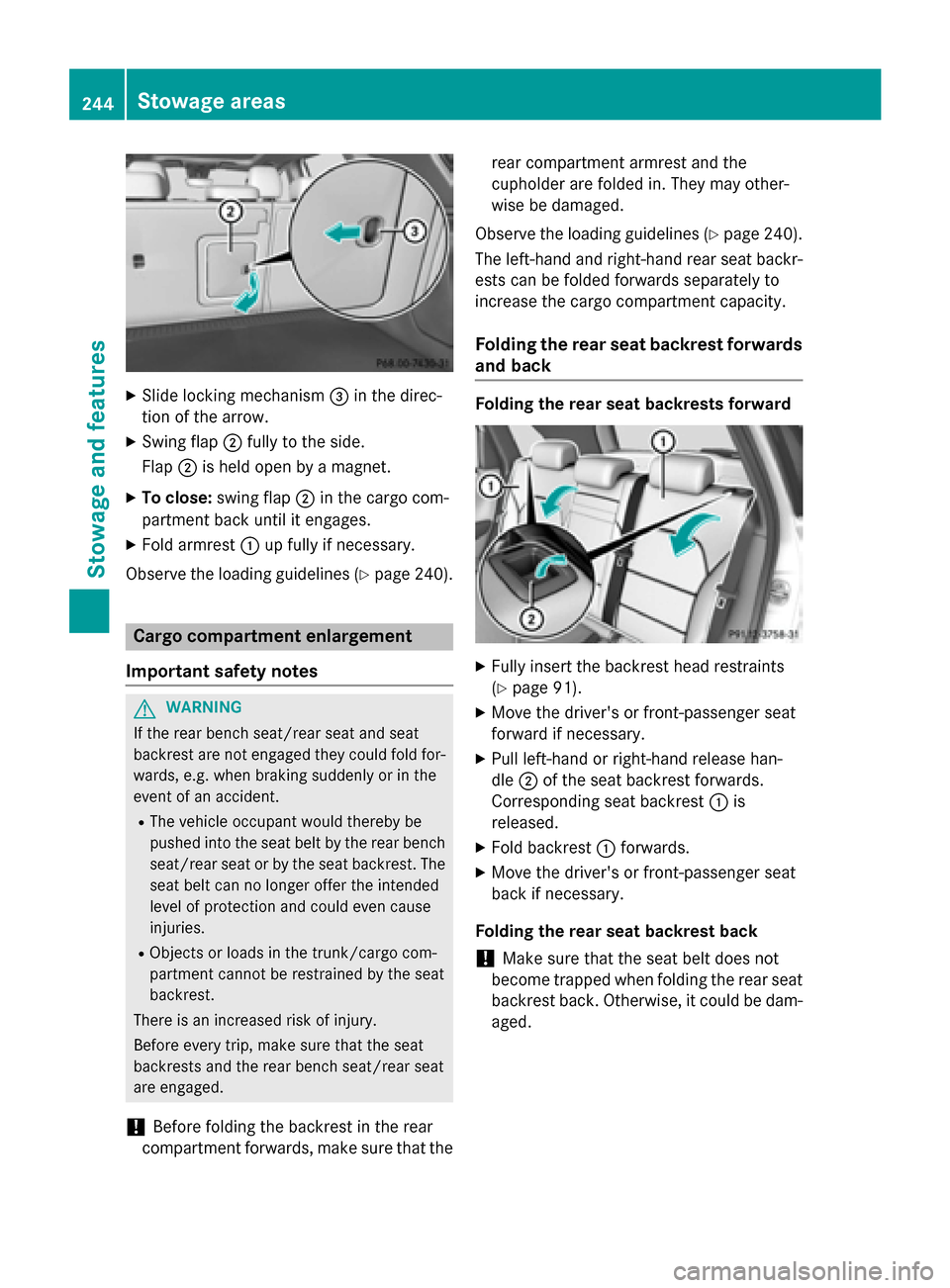
Slide locking mechanism =in the direc-
tion of the arrow.
X Swing flap ;fully to the side.
Flap ;is held open by a magnet.
X To close: swing flap ;in the cargo com-
partment back until it engages.
X Fold armrest :up fully if necessary.
Observe the loading guidelines (Y page 240).Cargo compartment enlargement
Important safety notes G
WARNING
If the rear bench seat/rear seat and seat
backrest are not engaged they could fold for- wards, e.g. when braking suddenly or in the
event of an accident.
R The vehicle occupant would thereby be
pushed into the seat belt by the rear bench
seat/rear seat or by the seat backrest. The
seat belt can no longer offer the intended
level of protection and could even cause
injuries.
R Objects or loads in the trunk/cargo com-
partment cannot be restrained by the seat
backrest.
There is an increased risk of injury.
Before every trip, make sure that the seat
backrests and the rear bench seat/rear seat
are engaged.
! Before folding the backrest in the rear
compartment forwards, make sure that the rear compartment armrest and the
cupholder are folded in. They may other-
wise be damaged.
Observe the loading guidelines (Y page 240).
The left-hand and right-hand rear seat backr- ests can be folded forwards separately to
increase the cargo compartment capacity.
Folding the rear seat backrest forwards
and back Folding the rear seat backrests forward
X
Fully insert the backrest head restraints
(Y page 91).
X Move the driver's or front-passenger seat
forward if necessary.
X Pull left-hand or right-hand release han-
dle ;of the seat backrest forwards.
Corresponding seat backrest :is
released.
X Fold backrest :forwards.
X Move the driver's or front-passenger seat
back if necessary.
Folding the rear seat backrest back ! Make sure that the seat belt does not
become trapped when folding the rear seat backrest back. Otherwise, it could be dam-
aged. 244
Stowage areasStowage and features
Page 337 of 338
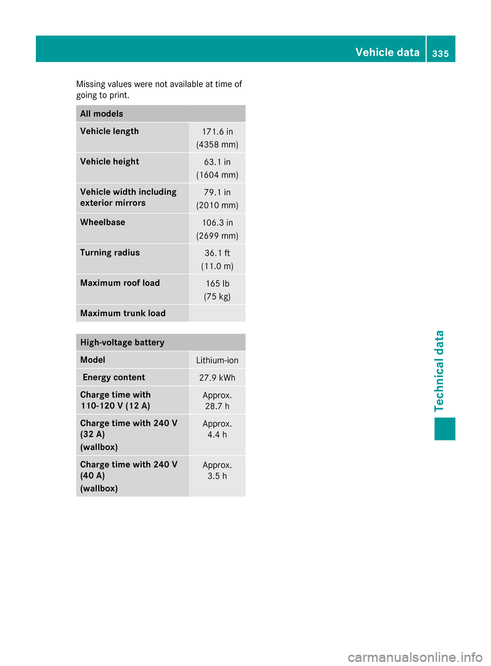
Missing values were not available at time of
going to print. All models
Vehicle length
171.6 in
(4358 mm) Vehicle height
63.1 in
(1604 mm) Vehicle width including
exterior mirrors
79.1 in
(2010 mm) Wheelbase
106.3 in
(2699 mm) Turning radius
36.1 ft
(11.0 m) Maximum roof load
165 lb
(75 kg) Maximum trunk load
High-voltage battery
Model
Lithium-ion
Energy content
27.9 kWh
Charge time with
110-120 V (12 A)
Approx.
28.7 h Charge time with 240 V
(32 A)
(wallbox)
Approx.
4.4 h Charge time with 240 V
(40 A)
(wallbox)
Approx.
3.5 h Vehicle data
335Technical data Z