2015 MERCEDES-BENZ B-Class ELECTRIC light
[x] Cancel search: lightPage 175 of 338
Under the following circumstances, the rear
view camera will not function, or will function
in a limited manner:
R if the trunk lid is open
R in heavy rain, snow or fog
R at night or in very dark places
R if the camera is exposed to very bright light
R if the area is lit by fluorescent bulbs or LED
lighting (the display may flicker)
R if there is a sudden change in temperature,
e.g. when driving into a heated garage in
winter
R if the camera lens is dirty or obstructed.
Observe the notes on cleaning
(Y page 276)
R if the rear of your vehicle is damaged. In this
event, have the camera position and setting checked at a qualified specialist workshop
The field of vision and other functions of the
rear view camera may be restricted due to
additional accessories on the rear of the vehi-
cle (e.g. license plate holder, bicycle rack).
Activating/deactivating the rear view
camera X
To activate: make sure that the key is in
position 2in the ignition lock.
X Make sure that the Activation by R Activation by R
gear
gear function is selected in Audio 20/
COMAND; see the Digital Operator's Man-
ual.
X Engage reverse gear.
The area behind the vehicle is shown with
guide lines in the Audio 20/COMAND dis-
play.
The image from the rear view camera is
available throughout the maneuvering
process.
To deactivate: the rear view camera deacti-
vates if you shift the transmission to Por after
driving forwards a short distance. Displays in the Audio 20/COMAND dis-
play The rear view camera may show a distorted
view of obstacles, show them incorrectly or
not at all. The rear view camera does not show
objects in the following positions:
R very close to the rear bumper
R under the rear bumper
R in the area immediately above the tailgate
handle
! Objects not at ground level may appear to
be further away than they actually are, e.g.:
R the bumper of a parked vehicle
R the drawbar of a trailer
R the ball coupling of a trailer tow hitch
R the rear section of an HGV
R a slanted post
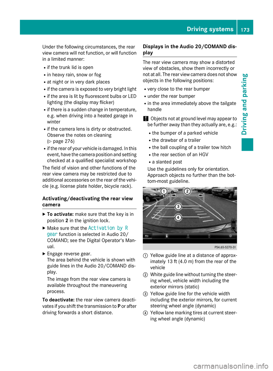
Use the guidelines only for orientation.
Approach objects no further than the bot-
tom-most guideline. :
Yellow guide line at a distance of approx-
imately 13 ft (4.0 m) from the rear of the
vehicle
; White guide line without turning the steer-
ing wheel, vehicle width including the
exterior mirrors (static)
= Yellow guide line for the vehicle width
including the exterior mirrors, for current
steering wheel angle (dynamic)
? Yellow lane marking tires at current steer-
ing wheel angle (dynamic) Driving systems
173Driving and parking Z
Page 176 of 338
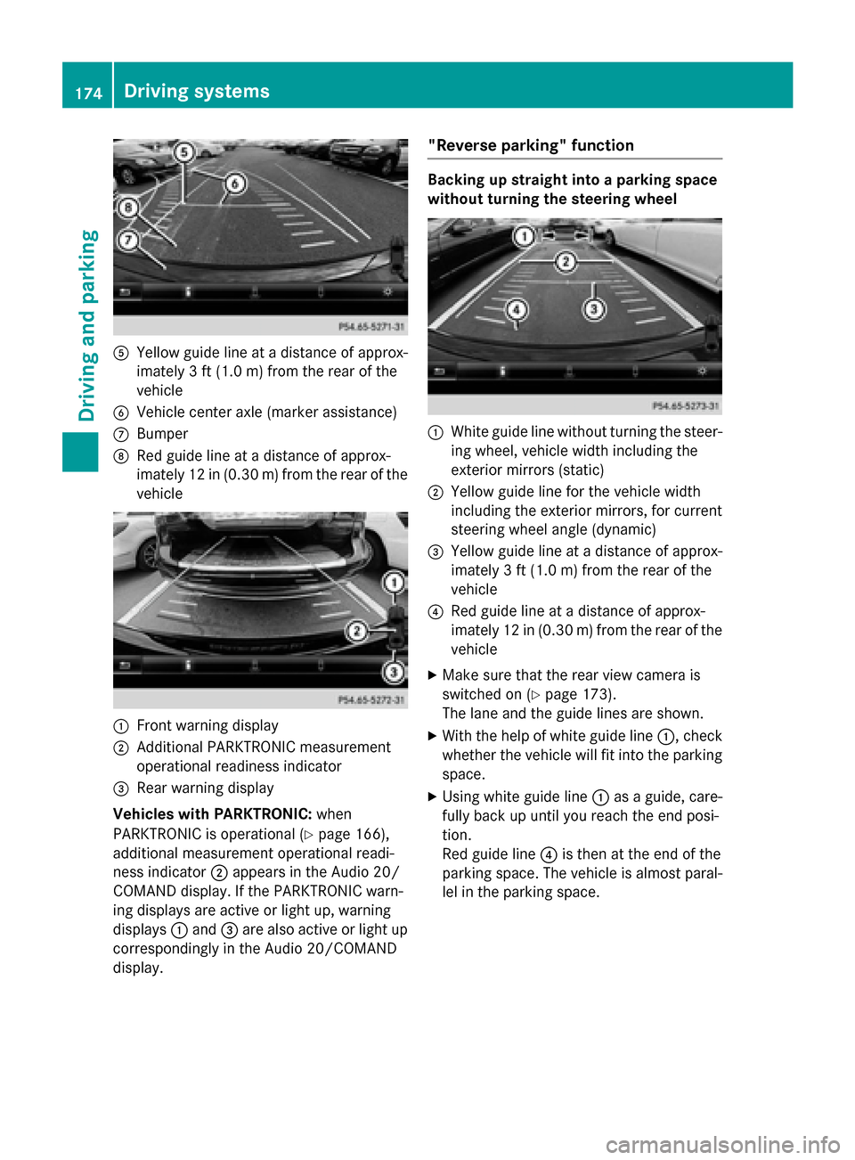
A
Yellow guide line at a distance of approx-
imately 3 ft (1.0 m) from the rear of the
vehicle
B Vehicle center axle (marker assistance)
C Bumper
D Red guide line at a distance of approx-
imately 12 in (0.30 m) from the rear of the
vehicle :
Front warning display
; Additional PARKTRONIC measurement
operational readiness indicator
= Rear warning display
Vehicles with PARKTRONIC: when
PARKTRONIC is operational (Y page 166),
additional measurement operational readi-
ness indicator ;appears in the Audio 20/
COMAND display. If the PARKTRONIC warn-
ing displays are active or light up, warning
displays :and =are also active or light up
correspondingly in the Audio 20/COMAND
display. "Reverse parking" function Backing up straight into a parking space
without turning the steering wheel
:
White guide line without turning the steer-
ing wheel, vehicle width including the
exterior mirrors (static)
; Yellow guide line for the vehicle width
including the exterior mirrors, for current
steering wheel angle (dynamic)
= Yellow guide line at a distance of approx-
imately 3 ft (1.0 m) from the rear of the
vehicle
? Red guide line at a distance of approx-
imately 12 in (0.30 m) from the rear of the
vehicle
X Make sure that the rear view camera is
switched on (Y page 173).
The lane and the guide lines are shown.
X With the help of white guide line :, check
whether the vehicle will fit into the parking space.
X Using white guide line :as a guide, care-
fully back up until you reach the end posi-
tion.
Red guide line ?is then at the end of the
parking space. The vehicle is almost paral-
lel in the parking space. 174
Driving systemsDriving and parking
Page 178 of 338
Wide-angle function
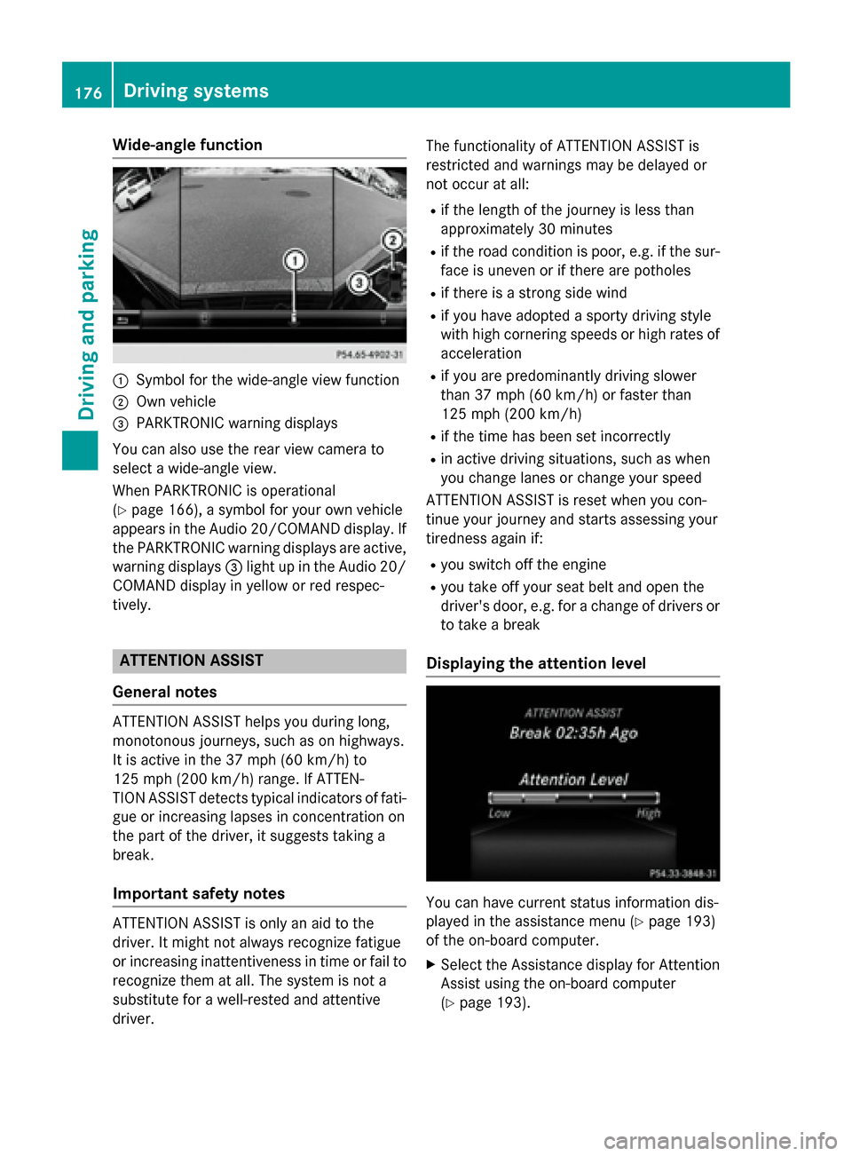
:
Symbol for the wide-angle view function
; Own vehicle
= PARKTRONIC warning displays
You can also use the rear view camera to
select a wide-angle view.
When PARKTRONIC is operational
(Y page 166), a symbol for your own vehicle
appears in the Audio 20/COMAND display. If the PARKTRONIC warning displays are active,
warning displays =light up in the Audio 20/
COMAND display in yellow or red respec-
tively. ATTENTION ASSIST
General notes ATTENTION ASSIST helps you during long,
monotonous journeys, such as on highways.
It is active in the 37 mph (60 km/h) to
125 mph (200 km/h) range. If ATTEN-
TION ASSIST detects typical indicators of fati- gue or increasing lapses in concentration on
the part of the driver, it suggests taking a
break.
Important safety notes ATTENTION ASSIST is only an aid to the
driver. It might not always recognize fatigue
or increasing inattentiveness in time or fail to
recognize them at all. The system is not a
substitute for a well-rested and attentive
driver. The functionality of ATTENTION ASSIST is
restricted and warnings may be delayed or
not occur at all:
R if the length of the journey is less than
approximately 30 minutes
R if the road condition is poor, e.g. if the sur-
face is uneven or if there are potholes
R if there is a strong side wind
R if you have adopted a sporty driving style
with high cornering speeds or high rates of
acceleration
R if you are predominantly driving slower
than 37 mph (60 km/h) or faster than
125 mph (200 km/h)
R if the time has been set incorrectly
R in active driving situations, such as when
you change lanes or change your speed
ATTENTION ASSIST is reset when you con-
tinue your journey and starts assessing your
tiredness again if:
R you switch off the engine
R you take off your seat belt and open the
driver's door, e.g. for a change of drivers or
to take a break
Displaying the attention level You can have current status information dis-
played in the assistance menu (Y
page 193)
of the on-board computer.
X Select the Assistance display for Attention
Assist using the on-board computer
(Y page 193). 176
Driving systemsDriving and parking
Page 181 of 338
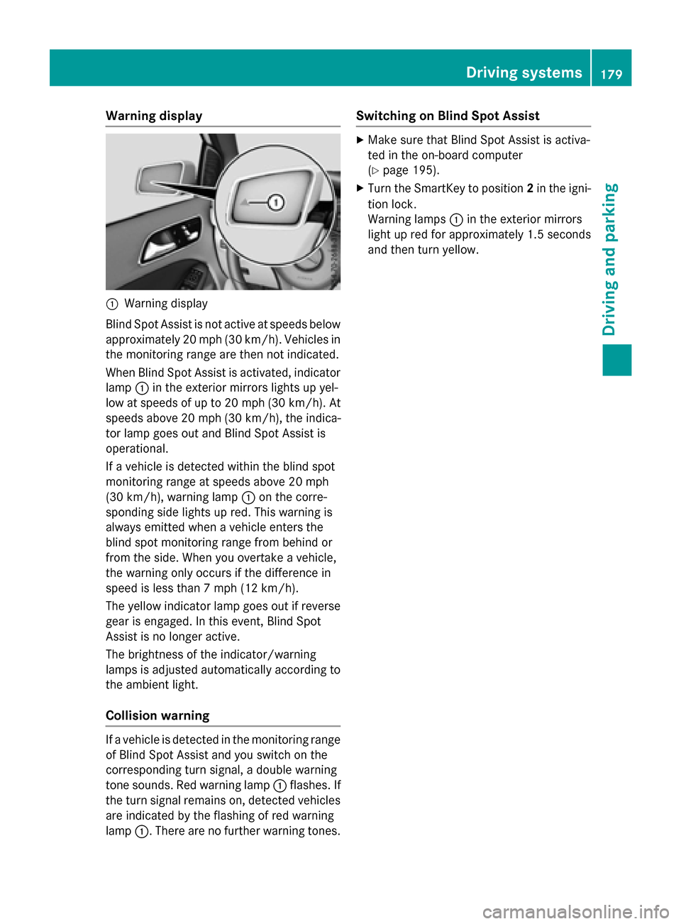
Warning display
:
Warning display
Blind Spot Assist is not active at speeds below approximately 20 mph (30 km/h). Vehicles in the monitoring range are then not indicated.
When Blind Spot Assist is activated, indicator
lamp :in the exterior mirrors lights up yel-
low at speeds of up to 20 mph (30 km/h). At speeds above 20 mph (30 km/h), the indica-
tor lamp goes out and Blind Spot Assist is
operational.
If a vehicle is detected within the blind spot
monitoring range at speeds above 20 mph
(30 km/h), warning lamp :on the corre-
sponding side lights up red. This warning is
always emitted when a vehicle enters the
blind spot monitoring range from behind or
from the side. When you overtake a vehicle,
the warning only occurs if the difference in
speed is less than 7 mph (12 km/h).
The yellow indicator lamp goes out if reverse gear is engaged. In this event, Blind Spot
Assist is no longer active.
The brightness of the indicator/warning
lamps is adjusted automatically according to
the ambient light.
Collision warning If a vehicle is detected in the monitoring range
of Blind Spot Assist and you switch on the
corresponding turn signal, a double warning
tone sounds. Red warning lamp :flashes. If
the turn signal remains on, detected vehicles
are indicated by the flashing of red warning
lamp :. There are no further warning tones. Switching on Blind Spot Assist X
Make sure that Blind Spot Assist is activa-
ted in the on-board computer
(Y page 195).
X Turn the SmartKey to position 2in the igni-
tion lock.
Warning lamps :in the exterior mirrors
light up red for approximately 1.5 seconds
and then turn yellow. Driving systems
179Driving and parking Z
Page 184 of 338
Useful information
i This Operator's Manual describes all
models and all standard and optional equip- ment of your vehicle available at the time of
publication of the Operator's Manual.
Country-specific differences are possible.
Please note that your vehicle may not be
equipped with all features described. This
also applies to safety-related systems and
functions.
i Read the information on qualified special-
ist workshops (Y page 25). Important safety notes
G
WARNING
If you operate information systems and com-
munication equipment integrated in the vehi- cle while driving, you will be distracted from
traffic conditions. You could also lose control of the vehicle. There is a risk of an accident.
Only operate the equipment when the traffic
situation permits. If you are not sure that this
is possible, park the vehicle paying attention
to traffic conditions and operate the equip-
ment when the vehicle is stationary.
You must observe the legal requirements for
the country in which you are currently driving when operating the on-board computer. G
WARNING
If the instrument cluster has failed or mal-
functioned, you may not recognize function
restrictions in systems relevant to safety. The operating safety of your vehicle may be
impaired. There is a risk of an accident.
Drive on carefully. Have the vehicle checked
at a qualified specialist workshop immedi-
ately.
The on-board computer only shows messages
or warnings from certain systems in the mul- tifunction display. You should therefore make sure your vehicle is operating safely at all
times.
If the operating safety of your vehicle is
impaired, pull over as soon as it is safe to do
so. Contact a qualified specialist workshop.
For an overview, see the instrument panel
illustration (Y page 31). Displays and operation
Instrument cluster lighting
The light sensor in the instrument cluster
automatically controls the brightness of the
multifunction display. In daylight, the displays
in the instrument cluster are not illuminated.
The lighting in the instrument cluster, in the
displays and the controls in the vehicle inte-
rior can be adjusted using the brightness con- trol knob.
The brightness control knob is located on the
bottom left of the instrument cluster
(Y page 31).
X Turn the brightness control knob clockwise
or counter-clockwise.
If the light switch is set to Ã,Tor
L, the brightness is dependent upon
the brightness of the ambient light. READY indicator
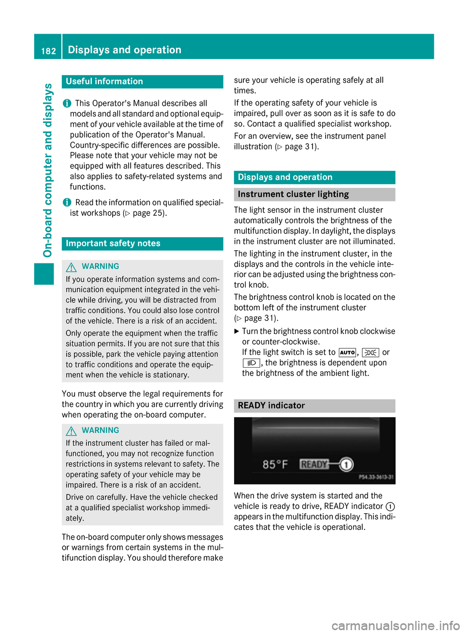
When the drive system is started and the
vehicle is ready to drive, READY indicator
:
appears in the multifunction display. This indi- cates that the vehicle is operational. 182
Displays and operationOn-board computer and displays
Page 186 of 338
The braking performance of the electric
motor using recuperative braking is, in some
operating modes, either reduced or not effec-
tive:
R when the condition of charge of the high-
voltage battery increases
R if the high-voltage battery is not yet at a
normal operating temperature
R when driving close to the maximum speed
R when the vehicle is almost stationary
R in transmission position N
R during and after ESP stability control
If necessary, counteract the reduced regen-
erative braking effect by applying the brake
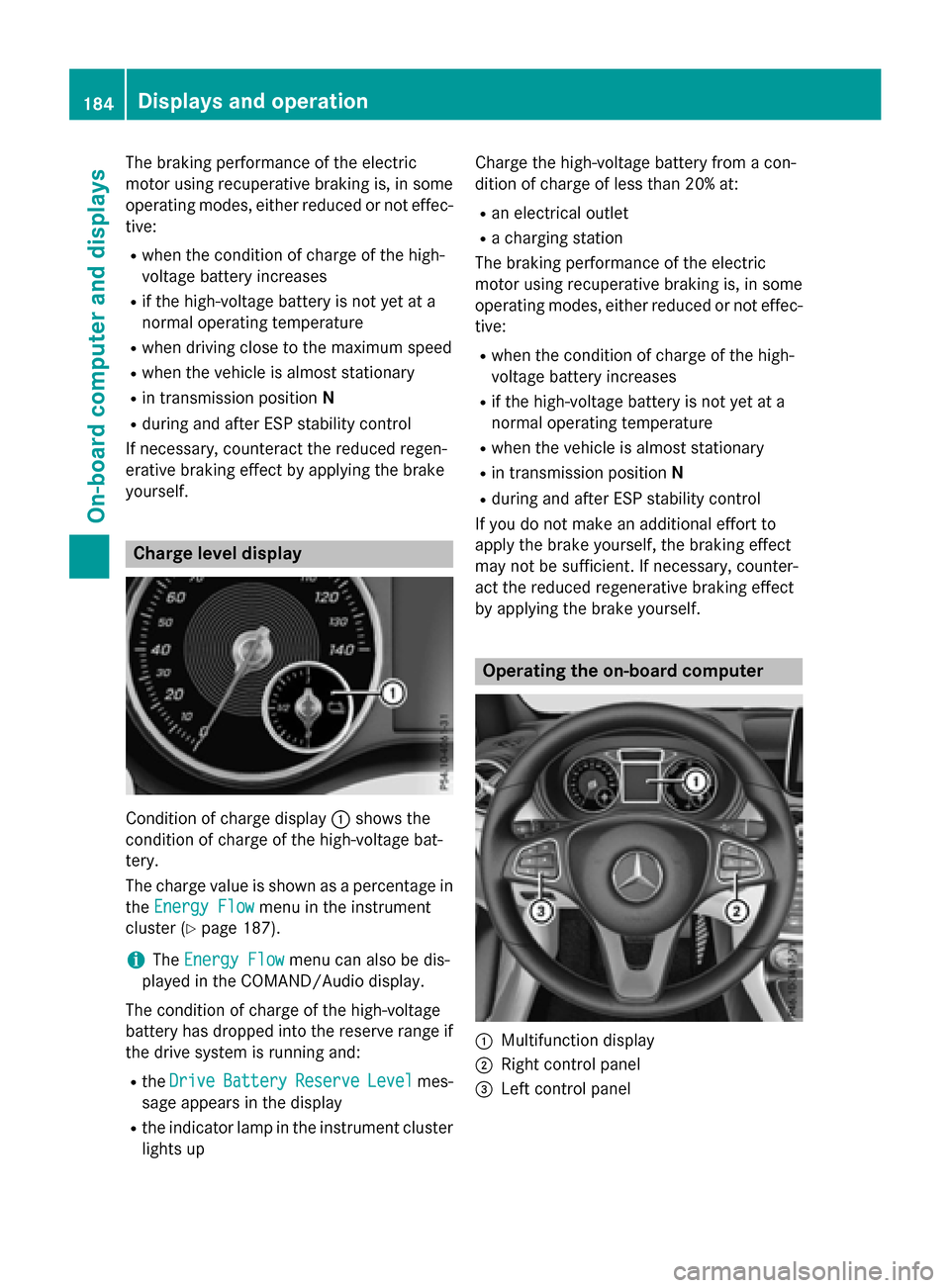
yourself. Charge level display
Condition of charge display
:shows the
condition of charge of the high-voltage bat-
tery.
The charge value is shown as a percentage in
the Energy Flow Energy Flow menu in the instrument
cluster (Y page 187).
i The
Energy Flow
Energy Flow menu can also be dis-
played in the COMAND/Audio display.
The condition of charge of the high-voltage
battery has dropped into the reserve range if
the drive system is running and:
R the Drive Drive Battery
Battery Reserve
ReserveLevel
Levelmes-
sage appears in the display
R the indicator lamp in the instrument cluster
lights up Charge the high-voltage battery from a con-
dition of charge of less than 20% at:
R an electrical outlet
R a charging station
The braking performance of the electric
motor using recuperative braking is, in some
operating modes, either reduced or not effec-
tive:
R when the condition of charge of the high-
voltage battery increases
R if the high-voltage battery is not yet at a
normal operating temperature
R when the vehicle is almost stationary
R in transmission position N
R during and after ESP stability control
If you do not make an additional effort to
apply the brake yourself, the braking effect
may not be sufficient. If necessary, counter-
act the reduced regenerative braking effect
by applying the brake yourself. Operating the on-board computer
:
Multifunction display
; Right control panel
= Left control panel 184
Displays and operationOn-board computer and displays
Page 188 of 338
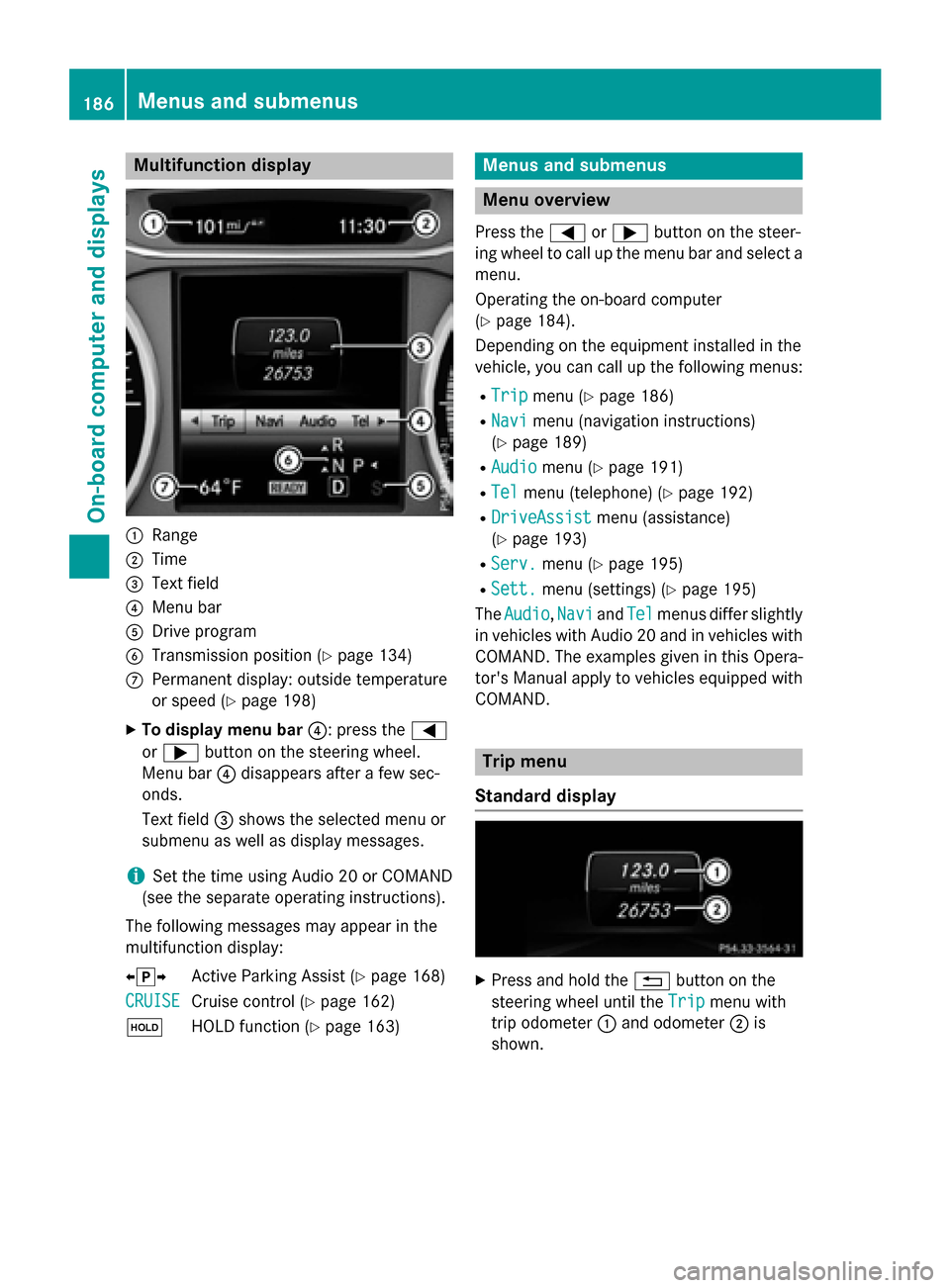
Multifunction display
:
Range
; Time
= Text field
? Menu bar
A Drive program
B Transmission position (Y page 134)
C Permanent display: outside temperature
or speed (Y page 198)
X To display menu bar ?: press the=
or ; button on the steering wheel.
Menu bar ?disappears after a few sec-
onds.
Text field =shows the selected menu or
submenu as well as display messages.
i Set the time using Audio 20 or COMAND
(see the separate operating instructions).
The following messages may appear in the
multifunction display:
XjY Active Parking Assist (Y page 168)
CRUISE
CRUISE Cruise control (Y
page 162)
ë HOLD function (Y page 163) Menus and submenus
Menu overview
Press the =or; button on the steer-
ing wheel to call up the menu bar and select a
menu.
Operating the on-board computer
(Y page 184).
Depending on the equipment installed in the
vehicle, you can call up the following menus:
R Trip Trip menu (Y page 186)
R Navi
Navi menu (navigation instructions)
(Y page 189)
R Audio
Audio menu (Y page 191)
R Tel
Tel menu (telephone) (Y page 192)
R DriveAssist
DriveAssist menu (assistance)
(Y page 193)
R Serv.
Serv. menu (Y page 195)
R Sett.
Sett. menu (settings) (Y page 195)
The Audio
Audio, Navi
NaviandTel
Tel menus differ slightly
in vehicles with Audio 20 and in vehicles with
COMAND. The examples given in this Opera-
tor's Manual apply to vehicles equipped with
COMAND. Trip menu
Standard display X
Press and hold the %button on the
steering wheel until the Trip
Trip menu with
trip odometer :and odometer ;is
shown. 186
Menus and submenusOn-board computer and displays
Page 189 of 338
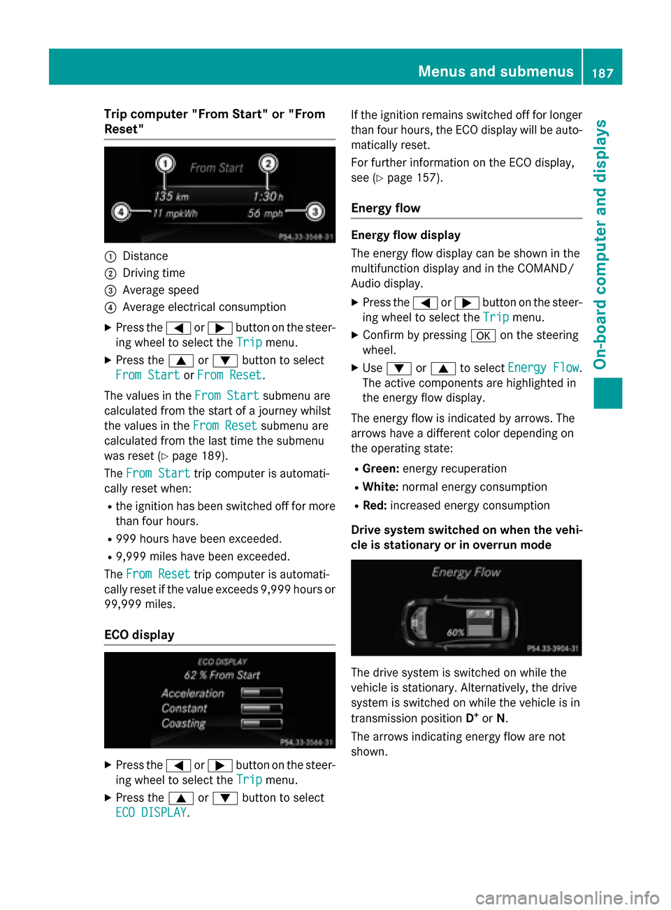
Trip computer "From Start" or "From
Reset" :
Distance
; Driving time
= Average speed
? Average electrical consumption
X Press the =or; button on the steer-
ing wheel to select the Trip
Tripmenu.
X Press the 9or: button to select
From Start
From Start orFrom Reset
From Reset.
The values in the From Start
From Startsubmenu are
calculated from the start of a journey whilst
the values in the From Reset From Resetsubmenu are
calculated from the last time the submenu
was reset (Y page 189).
The From Start From Start trip computer is automati-
cally reset when:
R the ignition has been switched off for more
than four hours.
R 999 hours have been exceeded.
R 9,999 miles have been exceeded.
The From Reset
From Reset trip computer is automati-
cally reset if the value exceeds 9,999 hours or 99,999 miles.
ECO display X
Press the =or; button on the steer-
ing wheel to select the Trip
Tripmenu.
X Press the 9or: button to select
ECO DISPLAY
ECO DISPLAY. If the ignition remains switched off for longer
than four hours, the ECO display will be auto-
matically reset.
For further information on the ECO display,
see (Y page 157).
Energy flow Energy flow display
The energy flow display can be shown in the
multifunction display and in the COMAND/
Audio display.
X Press the =or; button on the steer-
ing wheel to select the Trip Tripmenu.
X Confirm by pressing aon the steering
wheel.
X Use : or9 to select Energy Flow
Energy Flow .
The active components are highlighted in
the energy flow display.
The energy flow is indicated by arrows. The
arrows have a different color depending on
the operating state: R Green: energy recuperation
R White: normal energy consumption
R Red: increased energy consumption
Drive system switched on when the vehi-
cle is stationary or in overrun mode The drive system is switched on while the
vehicle is stationary. Alternatively, the drive
system is switched on while the vehicle is in
transmission position D+
or N.
The arrows indicating energy flow are not
shown. Menus and submenus
187On-board computer and displays Z