2015 MERCEDES-BENZ B-Class ELECTRIC service indicator
[x] Cancel search: service indicatorPage 6 of 338

1, 2, 3 ...
12 V socket see Sockets A
ABS (Anti-lock Braking System) Display message ............................ 201
Function/notes ................................ 63
Important safety notes .................... 63
Warning lamp .................................2 30
Accident
Automatic measures after an acci-
dent ................................................. 56
Activating/deactivating cooling
with air dehumidification ................. 118
Active Parking Assist
Detecting parking spaces .............. 169
Display message ............................ 220
Exiting a parking space .................. 171
Function/notes ............................ .168
Important safety notes .................. 168
Parking .......................................... 170
ADAPTIVE BRAKE ................................. 68
Adaptive Brake Assist
Function/notes ................................ 65
Adaptive Highbeam Assist
Function/notes ............................ .103
Switching on/off ........................... 104
Additional speedometer ................... 198
Air bag
Occupant Classification System
(OCS) ............................................... 49
Air bags
Deployment ..................................... 54
Display message ............................ 213
Front air bag (driver, front
passenger) ....................................... 47
Important safety notes .................... 46
Introduction ..................................... 46
Knee bag .......................................... 48
PASSENGER AIR BAG indicator
lamps ............................................... 41
Side impact air bag .......................... 48
Window curtain air bag .................... 48
Air vents
Important safety notes .................. 126 Rear ............................................... 127
Setting the center air vents ........... 126
Setting the side air vents ..............
.126
Air-conditioning system
see Climate control
Alarm
ATA (Anti-Theft Alarm system) ......... 69
Switching off (ATA) .......................... 69
Switching the function on/off
(ATA) ................................................ 69
Animals in the vehicle ......................... 62
Antenna ................................................ 24
Ashtray ............................................... 251
Assistance display (on-board com-
puter) ................................................. .193
Assistance menu (on-board com-
puter) ................................................. .193
ASSYST PLUS
Displaying a service message ....... .271
Driving abroad ............................... 272
Hiding a service message .............. 271
Information about Service ............. 271
Resetting the service interval dis-
pla y................................................ 271
Service message ............................ 270
Special service requirements ......... 271
ATA (Anti-Theft Alarm system)
Activating/deactivating ................... 69
Function ........................................... 69
Switching off the alarm .................... 69
ATTENTION ASSIST
Activating/deactivating ................. 194
Display message ............................ 219
Function/note s............................. 176
Audio menu (on-board computer) .... 191
Audio system
see separate operating instructions
Authorized Mercedes-Benz Center
see Qualified specialist workshop
AUTO lights
Display message ............................ 217
see Lights
Automatic car wash (care) ............... 272
Automatic headlamp mode .............. 100
Automatic transmission
Display message ............................ 223 4
Index
Page 12 of 338
Displaying the range (on-board
computer) ...................................... 188
Energy consumption ...................... 142
General notes ................................ 141
Method of operation ...................... 141
Outside temperatures .................... 142
Overvoltage protection .................. 145
Problems with the charging proc-
ess ................................................ .151
Reserve, warning lamp ................... 236
Terms of use .................................. 145
High-voltage disconnect device ......... 23
Hill start assist .................................. 134
HOLD function
Activating ....................................... 164
Deactivating ................................... 164
Display message ............................ 219
Function/notes ............................ .163
Hood
Closing .......................................... .269
Display message ............................ 224
Important safety notes .................. 268
Opening ......................................... 268
Horn ...................................................... 30
Hydroplaning ..................................... 161 I
Ignition lock see Key positions
Immobilizer .......................................... 69
Indicator and warning lamps
COLLISION PREVENTION ASSIST
PLUS .............................................. 237
Indicator lamps
see Warning and indicator lamps
Instrument cluster
Overview .......................................... 31
Power displa y................................ 183
Setting s......................................... 197
Warning and indicator lamps ........... 32
Instrument cluster lighting .............. 182
Interior lighting
Control ........................................... 105
Emergency lighting ........................ 106
Overview ........................................ 105
Reading lamp ................................. 105 Internet connection
Via mobile service modul e............. 153 J
Jack Storage location ............................ 280
Using ............................................. 322 K
Key positions Start/Stop button .......................... 131
KEYLESS-GO
Convenience closing feature ............ 84
Deactivation ..................................... 73
Locking ............................................ 73
Unlocking ......................................... 73
Kickdown
Driving tip s.................................... 137
Knee bag .............................................. 48 L
Lamps see Warning and indicator lamps
LATCH-type (ISOFIX) child seat
anchors ................................................ 58
License plate lamp
Changing bulbs .............................. 110
License plate lamp (display mes-
sage) ................................................... 215
Light function, active
Display message ............................ 216
Light sensor (display message) ....... 217
Lights
Adaptive Highbeam Assist ............. 103
Automatic headlamp mode ............ 100
Cornering light function ................. 103
Fogged up headlamp s.................... 104
Hazard warning lamps ................... 102
High beam flasher .......................... 102
High-beam headlamp s................... 102
Light switch ................................... 100
Low-beam headlamp s.................... 101
Parking lamps ................................ 101
Rear fog lamp ................................ 101
Setting exterior lighting ................. 100
Standing lamps .............................. 101 10
Index
Page 14 of 338
N
Navigation Menu (on-board computer) ............ 189
Notes on breaking-in a new vehi-
cle ....................................................... 130 O
Occupant Classification System
(OCS) Conditions ....................................... 49
Faults ............................................... 53
Operation ......................................... 49
System self-test ............................... 51
Occupant safety
Automatic measures after an acci-
dent ................................................. 56
Children in the vehicle ..................... 56
Important safety note s.................... 41
Introduction to the restraint sys-
tem .................................................. 40
Occupant Classification System
(OCS) ............................................... 49
PASSENGER AIR BAG indicator
lamps ............................................... 41
Pets in the vehicle ........................... 62
Restraint system warning lamp ........ 41
Seat belt .......................................... 42
OCS
Conditions ....................................... 49
Faults ............................................... 53
Operation ......................................... 49
System self-test ............................... 51
Odometer ........................................... 186
On-board computer
Assistance graphic menu ............... 193
Assistance menu ........................... 193
Audio menu ................................... 191
Display messages .......................... 200
Displaying a service message ........ 271
E‑CELL menu ................................. 195
Factory settings ............................. 199
Important safety notes .................. 182
Instrument cluster submenu .......... 197
Lighting submenu .......................... 198
Menu overview .............................. 186
Message memory .......................... 200 Navigation menu ............................ 189
Operation ....................................... 184
Service menu ................................. 195
Settings menu ............................... 195
Standard display ............................ 186
Telephone menu ............................ 192
Trip menu ...................................... 186
Vehicle submenu ........................... 198
Video DVD operation ..................... 191
Online access .................................... 152
Operating safety
Declaration of conformity ................ 24
Important safety notes .................... 22
Operating system
see On-board computer
Operator's Manual
Vehicle equipment ........................... 20
Outside temperature display ........... 183
Overhead control panel ...................... 37
Override feature
Rear side window s........................... 62 P
Paint code number ............................ 330
Paintwork (cleaning instructions) ... 273
Panic alarm .......................................... 40
Parking
Important safety notes .................. 153
Parking brake ................................ 155
Position of exterior mirror, front-
passenger sid e................................. 95
Rear view camera .......................... 172
see Active Parking Assist
see PARKTRONIC
Parking aid
Active Parking Assist ..................... 168
see Exterior mirrors
see PARKTRONIC
Parking brake
Display message ............................ 205
Electric parking brake .................... 155
Warning lamp ................................. 236
Parking lamps
Switching on/of f........................... 101
Parking lamps (changing bulbs) ...... 108
PARKTRONIC
Deactivating/activating ................. 167 12
Index
Page 18 of 338
Reached (TIREFIT) .......................... 284
Recommended ..............................
.303
Tire pressure monitor
Checking the tire pressure elec-
tronically ........................................ 309
Function/notes ............................ .307
General notes ................................ 307
Important safety notes .................. 307
Radio type approval for the tire
pressure monitor ........................... 310
Restarting ...................................... 309
Warning lamp ................................. 238
Warning message .......................... 309
TIREFIT kit .......................................... 282
Tires
Aspect ratio (definition) ................. 320
Average weight of the vehicle
occupants (definition) .................... 319
Bar (definition) ............................... 318
Changing a wheel .......................... 321
Characteristics .............................. 318
Checking ........................................ 301
Curb weight (definition) ................. 320
Definition of terms ......................... 318
Direction of rotatio n...................... 321
Display message ............................ 221
Distribution of the vehicle occu-
pants (definition) ............................ 321
DOT (Department of Transporta-
tion) (definition) ............................. 319
DOT, Tire Identification Number
(TIN) ............................................... 318
GAWR (Gross Axle Weight Rating)
(definition) ..................................... 319
General notes ................................ 325
GVW (Gross Vehicle Weight) (def-
inition) ........................................... 319
GVWR (Gross Vehicle Weight Rat-
ing) (definition) .............................. 319
Important safety notes .................. 300
Increased vehicle weight due to
optional equipment (definition) ...... 319
Information on driving .................... 300
Kilopascal (kPa) (definition) ........... 319
Labeling (overview) ........................ 315
Load bearing index (definition) ...... 320
Load index ..................................... 317
Load index (definition) ................... 319 M+S tire
s....................................... 302
Maximum load on a tire (defini-
tion) ............................................... 320
Maximum loaded vehicle weight
(definition) ..................................... 319
Maximum permissible tire pres-
sure (definition) ............................. 320
Maximum tire load ......................... 317
Maximum tire load (definition) ....... 320
MOExtended tire s.......................... 302
Optional equipment weight (defi-
nition) ............................................ 320
PSI (pounds per square inch) (def-
inition) ........................................... 320
Replacing ....................................... 321
Service life ..................................... 302
Sidewall (definition) ....................... 320
Speed rating (definition) ................ 319
Storing ........................................... 321
Structure and characteristics
(definition) ..................................... 318
Summer tire s................................. 302
Temperature .................................. 314
TIN (Tire Identification Number)
(definition) ..................................... 320
Tire bead (definition) ...................... 320
Tire pressure (definition) ................ 320
Tire pressures (recommended) ...... 319
Tire size (data) ............................... 325
Tire size designation, load-bearing capacity, speed rating .................... 315
Tire tread ....................................... 301
Tire tread (definition) ..................... 320
Total load limit (definition) ............. 321
Traction ......................................... 314
Traction (definition) ....................... 320
Tread wear ..................................... 314
Uniform Tire Quality Grading
Standards ...................................... 313
Uniform Tire Quality Grading
Standards (definition) .................... 319
Wear indicator (definition) ............. 320
Wheel and tire combination ........... 327
Wheel rim (definition) .................... 319
see Flat tire
Top Tether ............................................ 59
Towing away
Important safety guidelines ........... 292 16
Index
Page 179 of 338

The following information is displayed:
R length of the journey since the last break.
R the attention level determined by ATTEN-
TION ASSIST ( Attention Level
Attention Level), dis-
played in a bar display in five levels from
high to low
R If ATTENTION ASSIST is unable to calculate
the attention level and cannot issue a warn-
ing, the System Suspended System Suspended message
appears. The bar display then changes the
display, e.g. if you are driving at a speed
below 37 mph (60 km/h) or above 124 mph
(200 km/h).
Activating ATTENTION ASSIST X
Activate ATTENTION ASSIST using the on-
board computer (Y page 194).
The system determines the attention level
of the driver depending on the setting
selected:
Selection Standard
Standard: the sensitivity with
which the system determines the attention
level is set to normal.
Selection Sensitive Sensitive: the sensitivity is set
higher. The attention level detected by Atten- tion Assist is adapted accordingly and the
driver is warned earlier.
When ATTENTION ASSIST is deactivated, the é symbol appears in the multifunction
display in the assistance graphic display.
When ATTENTION ASSIST has been deactiva-
ted, it is automatically reactivated after the
engine has been stopped. The sensitivity
selected corresponds to the last selection
activated (standard/sensitive).
Warning in the multifunction display If fatigue or increasing lapses in concentra-
tion are detected, a warning appears in the
multifunction display:
ATTENTION ASSIST ATTENTION ASSIST
Take a Break! Take a Break!.
In addition to the message shown in the mul-
tifunction display, you will then hear a warn-
ing tone. X
If necessary, take a break.
X Confirm the message by pressing the a
button on the steering wheel.
On long journeys, take regular breaks in good
time to allow yourself to rest properly. If you
do not take a break and ATTENTION ASSIST
still detects increasing lapses in concentra-
tion, you will be warned again after
15 minutes at the earliest. This will only hap-
pen if ATTENTION ASSIST still detects typical indicators of fatigue or increasing lapses in
concentration.
If a warning is output in the multifunction dis-
play, a service station search is performed in
COMAND. You can select a service station
and navigation to this service station will then
begin. This function can be activated and
deactivated in COMAND. Blind Spot Assist
General notes Blind Spot Assist monitors the areas on either
side of the vehicle that are not visible to the
driver with two lateral, rear-facing radar sen-
sors. A warning display in the exterior mirrors draws your attention to vehicles detected in
the monitored area. If you then switch on thecorresponding turn signal to change lanes,
you will also receive a visual and audible col-
lision warning.
Blind Spot Assist supports you from a speed
of approximately 20 mph (30 km/h).
Important safety notes G
WARNING
Blind Spot Assist does not react to:
R vehicles overtaken too closely on the side,
placing them in the blind spot area
R vehicles which approach with a large speed
differential and overtake your vehicle
As a result, Blind Spot Assist may not give
warnings in such situations. There is a risk of an accident. Driving systems
177Driving and parking
Z
Page 256 of 338
A malfunction in the system has been detec-
ted if one of the following occurs:
R The indicator lamp in the SOS button does
not come on during the system self-test.
R The indicator lamp in the FRoadside
Assistance button does not light up during
self-diagnosis of the system.
R The indicator lamp in the ïMB Info call
button does not light up during self-diag-
nosis of the system.
R The indicator lamp in one or more of the
following buttons continues to light up red
after the system self-diagnosis:
- SOS button
- F Roadside Assistance call button
- ï MB Info call button
R The Inoperative
Inoperative or theService Not Service Not
Activated
Activated message appears in the multi-
function display after the system self-diag-
nosis.
If a malfunction is indicated as outlined
above, the system may not operate as expec-
ted. In the event of an emergency, help will
have to be summoned by other means.
Have the system checked at the nearest
authorized Mercedes-Benz Center or contact the following service hotlines:
Mercedes-Benz Customer Assistance Center
at 1-800-FOR-MERCede s (1-800-367-6372)
or 1-866-990-9007 Emergency call Important safety notes
G
WARNING
It can be dangerous to remain in the vehicle,
even if you have pressed the SOS button in an emergency if:
R you see smoke inside or outside of the vehi-
cle, e.g. if there is a fire after an accident
R the vehicle is on a dangerous section of
road
R the vehicle is not visible or cannot easily be
seen by other road users, particularly whendark or in poor visibility conditions
There is a risk of an accident and injury.
Leave the vehicle immediately in this or simi-
lar situations as soon as it is safe to do so.
Move to a safe location along with other vehi-
cle occupants. In such situations, secure the
vehicle in accordance with national regula-
tions, e. g. with a warning triangle.
General notes
Observe the notes on system activation
(Y page 253).
An emergency call is dialed automatically if an
air bag or Emergency Tensioning Device is
triggered. You cannot end an automatically
triggered emergency call yourself.
An emergency call can also be initiated man- ually.
As soon as the emergency call has been ini-
tiated, the indicator lamp in the SOS button
flashes. The Connecting Call Connecting Call message
appears in the multifunction display.
The audio output is muted.
Once the connection has been made, the
Call Connected Call Connected message appears in the
multifunction display. 254
FeaturesSto
wage an d features
Page 258 of 338
If a mobile phone network and GPS reception
are available, the system transfers data to the
Mercedes-Benz Customer Assistance Center, for example:
R current location of the vehicle
R vehicle identification number
The COMAND/Audio 20 display indicates
that a call is active. During the call, you can
change to the navigation menu by pressing
the NAVI button in COMAND/Audio 20, for
example.
Voice output is not available in this case.
A voice connection is established between
the Mercedes-Benz Customer Assistance
Center and the vehicle occupants.
From the remote malfunction diagnosis, the
Mercedes-Benz Customer Assistance Center
can ascertain the nature of the problem
(Y page 259).
The Mercedes-Benz Customer Assistance
Center either sends a qualified Mercedes-
Benz technician or makes arrangements for
your vehicle to be transported to the nearest authorized Mercedes-Benz Center.
You may be charged for services such as
repair work and/or towing.
You can find more information in the separatembrace manual.
The system has not been able to initiate a
Roadside Assistance call, if:
R the indicator lamp for Roadside Assistance
call button Fis flashing continuously.
R no voice connection to the Mercedes-Benz
Customer Assistance Center was estab-
lished.
This can occur if the relevant mobile phone
network is not available, for example.
The Call Failed
Call Failed message appears in the
multifunction display.
X To end a call: press the~button on the
multifunction steering wheel.
or
X Press the corresponding COMAND/Audio
20 button for ending a phone call. MB Info call button
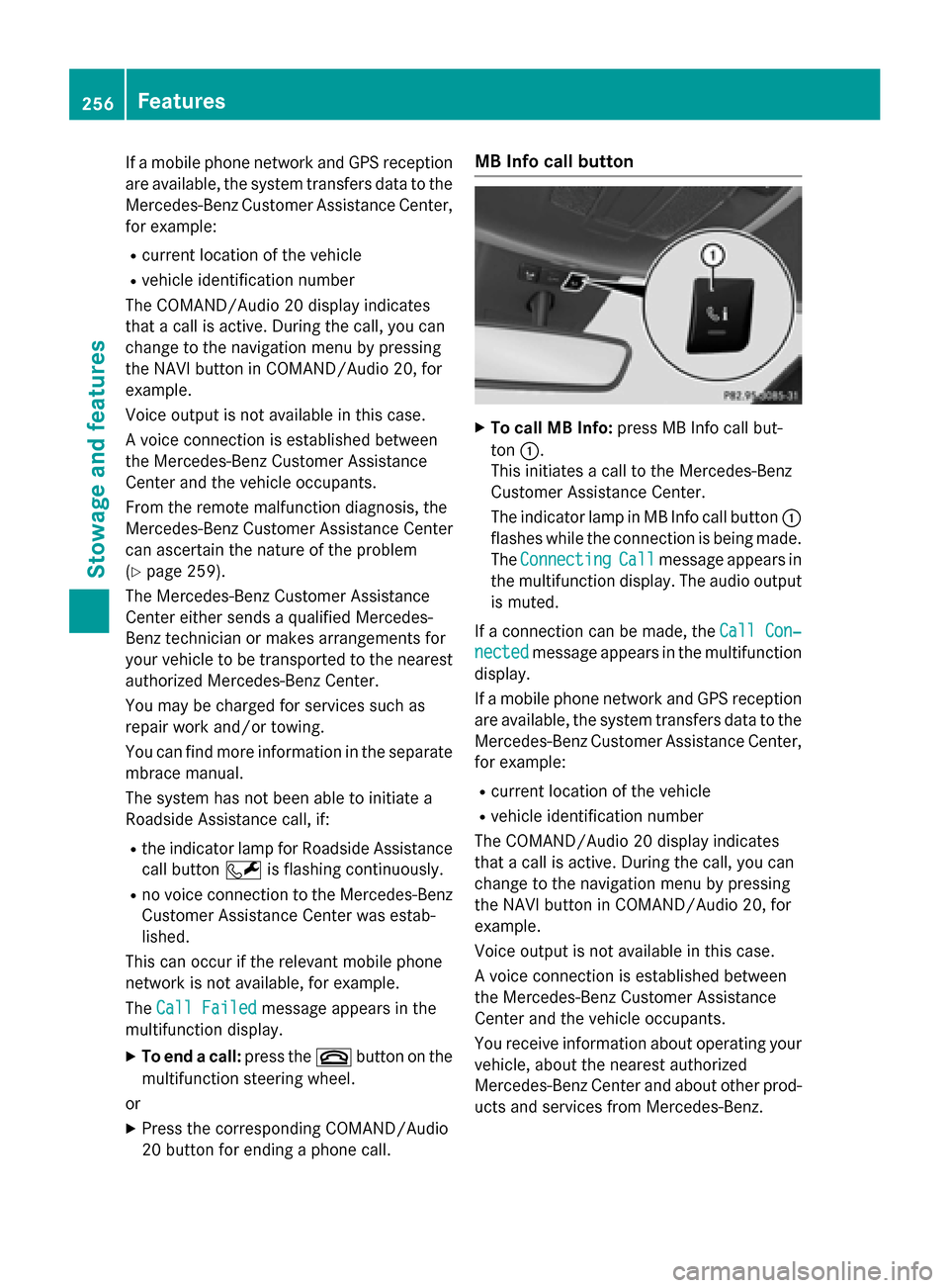
X
To call MB Info: press MB Info call but-
ton :.
This initiates a call to the Mercedes-Benz
Customer Assistance Center.
The indicator lamp in MB Info call button :
flashes while the connection is being made.
The Connecting Connecting Call Callmessage appears in
the multifunction display. The audio output
is muted.
If a connection can be made, the Call Con‐
Call Con‐
nected
nected message appears in the multifunction
display.
If a mobile phone network and GPS reception are available, the system transfers data to the
Mercedes-Benz Customer Assistance Center, for example:
R current location of the vehicle
R vehicle identification number
The COMAND/Audio 20 display indicates
that a call is active. During the call, you can
change to the navigation menu by pressing
the NAVI button in COMAND/Audio 20, for
example.
Voice output is not available in this case.
A voice connection is established between
the Mercedes-Benz Customer Assistance
Center and the vehicle occupants.
You receive information about operating your vehicle, about the nearest authorized
Mercedes-Benz Center and about other prod-
ucts and services from Mercedes-Benz. 256
FeaturesStowage and features
Page 259 of 338
You can find further information on the
mbrace system under "Owners Online" at
http://www.mbusa.com.
The system has not been able to initiate an
MB Info call, if:
R the indicator lamp in MB Info call button
ï is flashing continuously.
R no voice connection to the Mercedes-Benz
Customer Assistance Center was estab-
lished.
This can occur if the relevant mobile phone
network is not available, for example.
The Call Failed
Call Failed message appears in the
multifunction display.
X To end a call: press the~button on the
multifunction steering wheel.
or
X Press the corresponding COMAND/Audio
20 button for ending a phone call.
Call priority When service calls are active, e.g. Roadside
Assistance or MB Info calls, an emergency
call can still be initiated. In this case, an emer-
gency call will take priority and override all
other active calls.
The indicator lamp of the respective button
flashes until the call is ended.
An emergency call can only be terminated by the Mercedes-Benz Customer Assistance
Center.
All other calls can be ended by pressing:
R the ~ button on the multifunction steer-
ing wheel
R the corresponding button in COMAND/
Audio 20 to end the voice call
When a call is initiated, the audio system is
muted.
The mobile phone is no longer connected to
COMAND/Audio 20.
However, if you want to use your mobile
phone, do so only when the vehicle is station-
ary and in a safe location. Downloading destinations Downloading destinations
Downloading destinations gives you access
to a database with over 15 million points of
interest (POIs). These can be downloaded on
the navigation system in your vehicle. If you
know the destination, the address can be
downloaded. Alternatively, you can obtain the
location of Points of Interest (POIs)/impor-
tant destinations in the vicinity.
Furthermore, you can download routes with
up to four way points.
You are prompted to confirm route guidance
to the address entered.
X Select Yes
Yes by turning cVdor sliding XVY
the controller and confirm with W.
The system calculates the route and sub-
sequently starts the route guidance with
the address entered.
If you select No Nothe address can be stored in
the address book.
The destination download function is availa-
ble if: R the vehicle is equipped with a navigation
system.
R the relevant mobile phone network is avail-
able and data transfer is possible.
Route Assistance
This service is part of the mbrace PLUS Pack-
age and cannot be purchased separately.
You can use the route assistance function
even if the vehicle is not equipped with a nav- igation system.
Within the framework of this service, you
receive a professional and reliable form of
navigation support without having to leave
your vehicle.
The customer service representative finds a
suitable route depending on your vehicle's
current position and the desired destination.
You will then be guided live through the cur-
rent route section. Features
257Stowage and features Z