Page 57 of 81
*
Can alert you when a potential frontal collision with a vehicle or pedes\
trian is
determined")
106 || 107
DRIVING
DRIVING
*if equipped
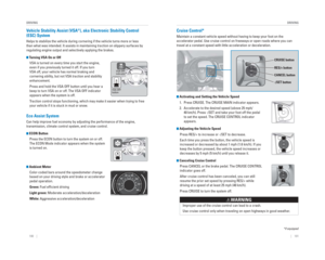
Collision Mitigation Braking System™ ( CMBS™)*
Can alert you when a potential frontal collision with a vehicle or pedes\
trian is
determined and reduce your vehicle speed when a collision is deemed unav\
oidable
to help minimize collision severity.
The system provides visual and audible alerts if you
do not take appropriate action to avoid a collision.
Alert Stages
The system has three alert stages for a possible
collision. Depending on the circumstances or
CMBS settings, CMBS may not go through all of
the stages before initiating the last stage.
Stage 1: Visual warnings and audible warning
Stage 2: Visual warnings, audible warning, and light brake application
Stage 3: Visual warnings, audible warning, and strong brake application
Turning CMBS On or OffPress and hold the CMBS OFF button. A beep sounds
and a message appears in the MID. The CMBS
indicator appears when the system is off.
Changing SettingsChange the alert distance. Use the steering wheel buttons to make and en\
ter
selections in the MID (see page 30).
1. Select the Customize Settings display.
2. Select Change Settings.
3. Select Driver Assist System Setup.
4. Select Forward Collision Warning Distance. Select Long, Normal, or Short.
5. Exit the menu.
Important Safety Reminder
CMBS is designed to help avoid collisions by automatically stopping the \
vehicle
when possible, and to reduce the severity of an unavoidable collision. I\
t is still your
responsibility to operate the brake pedal and steering wheel appropriate\
ly according
to the driving conditions.
Visual alert Beep
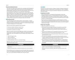
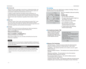
LaneWatch™*
Check the passenger -side rear areas in the upper display when the right turn signal
is activated.
LaneW atch display
Activating LaneWatch
Activate the right turn signal. The LaneWatch display
appears. Check the display for blind spots, and
visually confi rm that it is safe to change lanes.
You can also press the LaneWatch button on the end
of the turn signal switch to view a constant real-time
display. Press it again to turn the display off.
Changing SettingsCustomize the display and how and when the display appears.
1. From the HOME screen, select Settings.
2. Select Camera.
3. Select LaneWatch.
4. Select an option and make the preferred changes.
5. Press BACK to exit the menu.
Important Safety Reminder
Like all assistance systems, LaneWatch has limitations. Over-reliance on the system
may result in a collision.
Failure to visually confi rm that it is safe to change lanes before doing so may
result in a crash and serious injury or death.
Do not rely only on LaneW atch while driving. Always look in your mirrors, to
either side of your vehicle, and behind you for other vehicles before ch\
anging
lanes.
W ARNING
*if equipped
Page 58 of 81
, a real-time image of the area behind \
your vehicle is
shown in the i-MID, along with helpful par")
108 || 109
DRIVING
DRIVING
Multi-View Rear Camera*
When you shift into Reverse (R), a real-time image of the area behind \
your vehicle is
shown in the i-MID, along with helpful parking guidelines.
Models with one display
The rear camera view is restricted. You cannot see the corner ends of the bumper or what is
underneath the bumper. Its unique lens also makes objects appear closer or farther than they \
actually are.
Visually con� rm that it is safe to drive before backing up. Certain conditions (such\
as weather,
lighting, and high temperatures) may also restrict the rear view. Do not rely on the rearview display,
which does not give you all information about conditions at the rear of \
your vehicle.
Wide view Normal viewTop down view
Press the
selector knob
to change
views.
*if equipped
The rear camera view is restricted. Y ou cannot see the corner ends of the bumper or what is
underneath the bumper . Its unique lens also makes objects appear closer or farther than they \
actually are.
Visually con� rm that it is safe to drive before backing up. Certain conditions (such\
as weather ,
lighting, and high temperatures) may also restrict the rear view . Do not rely on the rearview display,
which does not give you all information about conditions at the rear of \
your vehicle.
Changing Camera Settings
Turn the guidelines on or off.
1. From the HOME screen, select Settings.
2. Select Camera.
3. Select Rear Wide Camera.
4. Select one of the options. Fixed Guideline: Guidelines appear when you
shift into Reverse. Select On or Off.
Dynamic Guideline: Guidelines move as you turn
the steering wheel. Select On or Off.
5. Press BACK to exit the menu.
*if equipped
Multi-View Rear Camera*
When you shift into Reverse (R), a real-time image of the area behind \
your vehicle is
shown in the touchscreen, along with helpful parking guidelines.
Models with touchscreen
Wide view Normal viewTop down view
Press the icons on the touchscreen to change views.
Page 59 of 81

110 || 111
HANDLING THE UNEXPECTED
DRIVING
Refueling
Use the proper fuel and refueling procedure to ensure the best performan\
ce and
safety of your vehicle.
Fuel Information
Use of unleaded gasoline of 87 octane or higher is recommended.
• Honda recommends TOP TIER Detergent Gasoline where available.
• Do NOT use gasoline containing more than 15% ethanol.
• Do NOT use gasoline containing methanol.
• Do NOT use gasoline containing MMT.
How to Refuel
1. The fuel fi ll door is located at the left rear of the vehicle. Park next to the service pump that is
most accessible.
2. Turn off the engine.
3. Pull the fuel fi ll door release handle near the parking brake. The fuel fi ll door opens.
4. Turn the fuel fi ll cap slowly to open. Place the fuel fi ll cap in the holder.
5. Insert the fi ller nozzle fully. When the tank is full, the fuel nozzle clicks off automatically.
6. Replace the fuel fi ll cap. Tighten it until you hear at least one click. Close the fuel fi ll door.
We recommend quality gasoline containing detergent additives that help
prevent fuel system and engine deposits. In addition, in order to mainta\
in good
performance, fuel economy, and emissions control, we strongly recommend the
use of gasoline that does NOT contain harmful manganese-based fuel addit\
ives
such as MMT, if such gasoline is available.
NOTICE
Pull
Holder
Gasoline is highly fl ammable and explosive. You can be burned or seriously
injured when handling fuel.
• Stop the engine, and keep heat, sparks, and fl ame away.
• Handle fuel only outdoors.
• Wipe up spills immediately.
WARNING
Learn about what to do in critical or emergency situations.
Smart Entry Remote Battery Strength*
If the battery life in your remote transmitter is weak, a message appear\
s in the
display with information on how to start the engine.
1. Touch the back of the remote transmitter to the
ENGINE START/STOP button while the indicator is
fl ashing.
2. With the brake pedal pressed, press the ENGINE START/STOP button within 10 seconds.
Jump Starting
Turn off the power to electric devices, such as audio and lights. Turn off the engine,
then open the hood.
1. Connect the fi rst jumper cable to your vehicle’s battery (+) terminal.
2. Connect the other end of the fi rst jumper cable to the booster battery (+) terminal. Use a 12-volt
booster battery only.
3. Connect the second jumper cable to the booster battery (-) terminal.
4. Connect the other end of the second jumper cable to the engine mounting bolt as shown. Do not
connect this jumper cable to any other part.
5. If your vehicle is connected to another vehicle, start the assisting vehicle’s engine and increase its
rpm slightly.
6. Attempt to start your vehicle’s engine. If it turns over slowly, make sure that the jumper cables have
good metal-to-metal contact.
WARNING: Battery posts, terminals, and related accessories contain lead and lead\
compounds. Wash your hands after handling.
Booster battery
A battery can explode if you do not follow the correct procedure, seriou\
sly
injuring anyone nearby.
Keep all sparks, open fl ames, and smoking materials away from the battery.
WARNING
HANDLING THE UNEXPECTED
*if equipped
Page 60 of 81

112 || 113
HANDLING THE UNEXPECTED
HANDLING THE UNEXPECTED
After the Engine Starts
Once your vehicle’s engine has started, remove the jumper cables in the following
order:
1. Disconnect the jumper cable from your vehicle’s ground.
2. Disconnect the other end of the jumper cable from the assisting vehicle’\
s (-) terminal.
3. Disconnect the jumper cable from your vehicle’s (+) terminal.
4. Disconnect the other end of the jumper cable from the assisting vehicle’\
s (+) terminal.
5. Have your vehicle inspected by a nearby service station or a dealer.
Shift Lever Does Not Move
Follow the procedure below if you cannot move the shift lever out of Par\
k (P).
1. Set the parking brake.
2. Remove the key from the ignition, or remove the built-in key from the remote transmitter.
3. Wrap a cloth around the tip of a small fl at-tip screwdriver to remove the cover of the shift lock
release slot. Put the tip of the fl at-tip screwdriver
into the slot and remove it as shown in the image.
4. Insert the key into the shift lock release slot.
5. While pushing the key down, press the shift lever release button and place the shift lever into Neutral
(N). The lock is now released. Have the shift lever
checked by a dealer as soon as possible.
Slot
Release
button
Shift lock
release slot
Overheating
If the temperature gauge needle is at the H mark, the engine suddenly lo\
ses power,
or steam or spray comes out from under the hood, your engine is overheat\
ing.
1. Immediately park the vehicle in a safe place. Turn off all accessories and turn on the hazard warning
lights.
2. If steam or spray is not present: Keep the engine
running and open the hood.
If steam or spray is present: Turn off the engine and wait until it subsides. Then, open the hood.
3. Check that the cooling fan is operating and stop the engine once the tem\
perature gauge needle comes down. If the cooling fan is not operating, immediatel\
y stop
the engine.
4. Once the engine has cooled down, inspect the coolant level and check the\
cooling system components for leaks. If the coolant level in the reserve\
tank
is low, add coolant until it reaches the MAX mark. If there is no coolant in t\
he
reserve tank, make sure the radiator is cool, then cover the radiator ca\
p with a
heavy cloth and open the cap. If necessary, add coolant up to the base of the
fi ller neck, and put the cap back on.
Once the engine has cooled suffi ciently, restart it and check the temperature gauge.
If the temperature needle has gone down, resume driving. If it has not g\
one down,
contact a dealer for repairs.
Reserve tank
MAX
MIN
Steam and spray from an overheated engine can seriously scald you.
Do not open the hood if steam is coming out.
WARNING
Removing the radiator cap while the engine is hot can cause the coolant \
to
spray out, seriously scalding you.
Always let the engine and radiator cool down before removing the radiato\
r cap.
WARNING
Continuing to drive with the temperature gauge needle at the H mark may \
damage
the engine.
NOTICE
Page 61 of 81

114 || 115
HANDLING THE UNEXPECTED
HANDLING THE UNEXPECTED
Emergency Engine Stop*
The ENGINE START/STOP button may be used to stop the engine due to an
emergency situation even while driving. If you must stop the engine, cho\
ose one of
the following operations:
• Press and hold the ENGINE START/STOP button for
two seconds, or
• Firmly press the ENGINE START/STOP button two times.
The steering wheel will not lock. The power mode changes to ACCESSORY, unless
the shift lever is in Park (P), in which case the power mode changes t\
o VEHICLE OFF.
Because turning off the engine also disables the power assist the engine\
provides
to the steering and braking systems, it will require signifi cantly more physical effort
and time to steer and slow the vehicle. Downshift gears and use both fee\
t on the
brake pedal, if necessary, to slow the vehicle and stop immediately in a safe place.
Do not press the button while driving unless it is absolutely necessary \
for the engine
to be switched off.
Emergency Towing
Call a professional towing service if you need to tow your vehicle.
Flat bed equipment: The operator loads your vehicle on the back of a tru\
ck. This is
the best way to transport your vehicle.
Wheel lift equipment: The tow truck uses two pivoting arms that go under\
the front
tires and lift them off the ground. The rear tires remain on the ground.\
This is an
acceptable way to tow your vehicle (2WD models only).
Trying to lift or tow your vehicle by the bumpers will cause serious dama\
ge. The
bumpers are not designed to support the vehicle’s weight.
Improper towing such as towing behind a motorhome or other motor vehicle\
can
damage the transmission.
NOTICE
*if equipped
Tire Pressure Monitoring System ( TPMS)
Monitors the tire pressure while you are driving.
If your vehicle’s tire pressure becomes signifi cantly low,
the low tire pressure indicator comes on and a message
appears on the multi-information display.
What to Do Stop your vehicle in a safe place. Check the tire
pressure and adjust the pressure to the specifi ed
level. The specifi ed tire pressure is on a label on the
driver’s doorjamb.
TPMS CalibrationAny time you infl ate, change, or rotate one of more of the tires, you need to
recalibrate the system.
On vehicles with information display
Press and hold the TPMS button on the dashboard.
The TPMS indicator blinks, and calibration begins.
On vehicles with multi-information display (MID)
Use the buttons on the steering wheel to enter and operate the Vehicle Settings
menu (see page 30).
1. Scroll to the Vehicle Settings screen and enter the menu.
2. Select TPMS Calibration.
3. Select Calibrate. Calibration begins.
4. Exit the menu.
Driving on an extremely underinfl ated tire can cause it to overheat. An overheated
tire can fail. Always infl ate your tires to the specifi ed pressure.
NOTICE
Page 62 of 81

116 || 117
HANDLING THE UNEXPECTED
HANDLING THE UNEXPECTED
Changing a Flat Tire
If a tire goes fl at while driving, grasp the steering wheel fi rmly, and brake gradually
to reduce speed. Then, stop in a safe place. Replace the fl at tire with the compact
spare tire. Go to a dealer as soon as possible to have the full-size tir\
e repaired or
replaced.
Getting Ready to Change the Tire
Park the vehicle on a fi rm, level, non-slippery surface. Apply the parking brake,
shift to Park (P), and turn the vehicle off. Turn on the hazard warning lights.
1. Open the tailgate. Turn on the cargo lights if necessary (see page 39).
2. Open the cargo area fl oor lid.
3. Take the tool bag out of the cargo area. Take the jack handle bar and wheel nut wrench out of the
tool bag.
4. Take the jack out of the spare tire area.
5. Unscrew the wing bolt and remove the spacer cone. Then remove the spare tire.
6. Place a wheel block or rock in front and rear of the wheel diagonal to the fl at tire.
7. Place the compact spare tire (wheel side up) under the vehicle body, near the tire that needs
to be replaced.
8. Loosen each wheel nut about one turn using the wheel nut wrench.
Tool bagSpare tire
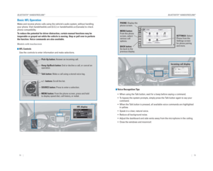
Setting Up the Jack
1. Place the jack under the jacking point closest to the tire to be changed.
2. Turn the end bracket clockwise (as shown in the image) until the top of the jack contacts the
jacking point. Make sure that the jacking point
tab is resting in the jack notch.
3. Raise the vehicle, using the jack handle bar and the jack handle, until the tire is off the ground.
The following instructions must be followed to use the jack safely:
• Do not use the jack with people or luggage in the vehicle.
• Use the jack provided in your vehicle. Other jacks may not support the w\
eight (“load”) or fi t the jacking point.
• Do not use while the engine is running.
• Use only where the ground is fi rm and level.
• Use only at the jacking points.
• Do not get in the vehicle while using the jack.
• Do not put anything on top of or underneath the jack.
Jack
handle
bar Wheel nut
W rench as jack handle
The vehicle can easily roll off the jack, seriously injuring anyone unde\
rneath.
Follow the directions for changing a tire exactly , and never get under the
vehicle when it is supported only by the jack.
W ARNING
Page 63 of 81

118 || 119
HANDLING THE UNEXPECTED
HANDLING THE UNEXPECTED
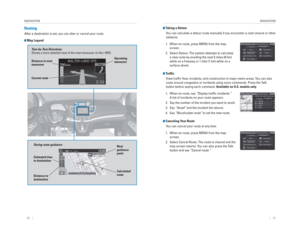
Replacing the Flat Tire
1. Remove the wheel nuts and fl at tire.
2. Mount the compact spare tire. Replace the wheel nuts, and lightly tighten them.
3. Lower the vehicle and remove the jack. Tighten the wheel nuts in the order indicated in the
image. Go around, tightening the nuts, two to
three times in this order. Do not overtighten the
wheel nuts.
If you drive with the spare tire installed, the
low tire pressure/TPMS indicator appears. The
indicator stays on until a regular tire is installed.
Storing the Flat Tire 1. Remove the center cap.
2. Place the fl at tire face down in the spare tire well.
3. Remove the spacer cone from the wing bolt, fl ip it over, and insert it back on the bolt. Secure the
fl at tire with the wing bolt.
4. Securely store the wheel nut wrench and jack handle bar back in the tool bag. Store the bag in
the cargo area.
5. Store the jack in its holder. Turn the jack’s end bracket to lock it in place.
Wing bolt
Spacer
cone For compact
spare tire
For full-size tire
Loose items can fl y around the interior in a crash and can seriously injure the
occupants.
Store the wheel, jack, and tools securely before driving.
WARNING
Fuse Locations
If any electrical devices are not working, turn the vehicle off and chec\
k to see if any
applicable fuse is blown. Fuse locations are shown on the fuse box cover\
. Locate the
fuse in question by the fuse number and box cover number.
Engine Compartment Fuse Box Located under the hood near the brake fl uid reservoir. Push the tabs to open the
box.
89VSA ECU7.5 A
10 (7.5 A)
11STRLD7.5 A
12 (20 A)
13Premium Amp*(20 A)
14
15Hazard10 A
16
17IG Coil15 A
18
19Daytime Running Lights(10 A)
20 Passenger’s Power Seat
Reclining (20 A)
21Deicer(15 A)
22
23IGP15 A
24
25Right Headlight Low Beam10 A
26
27MG Clutch7.5 A
28
29Backup10 A
Circuit ProtectedAmps7.5 A
10 A10 A
15 A
15 A
10 A
20 A
7.5 A
Sub Fan Rly CL
HornStop
IGP2
DBW
Left Headlight Low Beam SMALL
Interior Lights
Heated Door Mirror
*
Front Fog Lights*
Circuit ProtectedAmps
1
EPS70 APower Tailgate(40 A)ABS/VSA FSR20 AABS/VSA Motor40 AE-DPS*(30 A)Main Fuse120 A
2
Main50 A
Fuse Box Main
Fuse Box Main 260 A
Headlight High Beam Main
ST Magnetic Switch(30 A)
Rear Defogger −
Heater Motor
Front Wiper Main Sub Fan Motor
Main Fan Motor
3
DC/DC1(30 A)DC/DC2(30 A)IG MAIN(30 A)IG MAIN2(30 A)
4
5−−
6
7−−
60 A
30 A
30 A −
40 A
30 A 20 A
20 A
−
−
−
−
*if equipped
Ta
b
Page 64 of 81

120 || 121
HANDLING THE UNEXPECTED
HANDLING THE UNEXPECTED
Circuit ProtectedAmps1−−2ACG10 A3SRS10 A4Fuel Pump15 A
5Meter10 A6Power Window7.5 A7VB SOL7.5 A
8Passenger’s Side Door Lock
Motor 2 (Unlock)15 A
9Driver’s Side Door Lock Motor 1 (Unlock)15 A
10 (7.5 A)
11Moonroof*(20 A)
12 Accessory Power Socket
(Center Console) 20 A
13Washer Main*(15 A)
14 (20 A)
15Driver’s Door Lock Motor
(Unlock)10 A
16 (20 A)
17Driver's Power Seat
Reclining*(20 A)
18
19ACC7.5 A−−
Driver's Power Seat Sliding
*
Seat Heaters*
Trailer*
2021Daytime Running Lights7.5 A
22
23Wiper10 A
24
25Audio10 A
26 (20 A)
27Accessory Power Socket
(Front)20 A
28 15 A
29OPDS7.5 A
30 Driver’s Door Lock Motor
(Lock) 10 A
31Smart*(10 A)
32 Passenger’s Side Door Lock
Motor 2 (Lock) 15 A
33Driver’s Side Door Lock
Motor 1 (Lock)15 A
34
35Illumination7.5 A
36 (10 A)
37Front Fog Lights*(20 A)
38
3910 A
40
41Door Lock20 A
42 Driver’s Side Power
Window 20 A
43Rear Passenger’s Side
Power Window20 A
44 Front Passenger’s Side
Power Window 20 A
45Rear Driver’s Side Power
Window20 A
46
Circuit ProtectedAmps
Washer*
Power Tailgate*
7.5 A
ABS/VSA 7.5 A
A/C 7.5 A
ACC Key Lock
Right Headlight High Beam −− 10 A
Left Headlight High Beam Rear Wiper Main
*
10 A
Small Lights
−
−
Interior Fuse Box
Located under the dashboard.
*if equipped
Fuse label
Fuse box
Inspecting and Changing Fuses
1. Turn the vehicle off, including all lights and accessories.
2. Remove the fuse box cover.
3. Check the large fuse in the engine compartment.
If the fuse is blown, use a Phillips-head screwdriver to remove the screws and replace
the fuse with a new one. Reinstall the screws.
4. Inspect the small fuses in the engine compartment and the vehicle interior.
If there is a burned-out fuse, remove it with the fuse puller and replace it with a new one.
Blown fuse Combined fuse
Fuse
puller
Replacing a fuse with one that has a higher rating greatly increases the\
chances
of damaging the electrical system.
NOTICE