2015 FORD SUPER DUTY lock
[x] Cancel search: lockPage 258 of 470
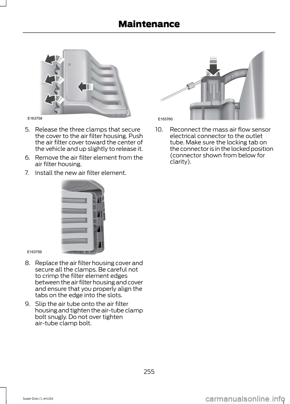
5.Release the three clamps that securethe cover to the air filter housing. Pushthe air filter cover toward the center ofthe vehicle and up slightly to release it.
6.Remove the air filter element from theair filter housing.
7.Install the new air filter element.
8.Replace the air filter housing cover andsecure all the clamps. Be careful notto crimp the filter element edgesbetween the air filter housing and coverand ensure that you properly align thetabs on the edge into the slots.
9.Slip the air tube onto the air filterhousing and tighten the air-tube clampbolt snugly. Do not over tightenair-tube clamp bolt.
10.Reconnect the mass air flow sensorelectrical connector to the outlettube. Make sure the locking tab onthe connector is in the locked position(connector shown from below forclarity).
255Super Duty (), enUSAMaintenanceE163758 E163759 E163760
Page 260 of 470
•Wash your vehicle first, using cool orlukewarm water and a neutral pHshampoo, such as Motorcraft DetailWash.
•Use Motorcraft Custom Bright MetalCleaner. Apply the product as youwould a wax to clean bumpers andother chrome parts; allow the cleanerto dry for a few minutes, then wipe offthe haze with a clean, dry rag.
•Do not apply cleaning product to hotsurfaces and do not leave cleaningproduct on chrome surfaces longerthan the time recommended.
•Using other non-recommendedcleaners can result in severe andpermanent cosmetic damage.
Underbody
Flush the complete underside of yourvehicle frequently. Keep body and doordrain holes free from packed dirt.
Cleaning Plastic Exterior Parts
Use only approved products to cleanplastic parts
•For routine cleaning, use MotorcraftDetail Wash.
•If tar or grease spots are present, useMotorcraft Bug and Tar Remover.
WAXING
Regular waxing is necessary to protect yourcar's paint from the elements. Werecommend that you wash and wax thepainted surface once or twice a year.
When washing and waxing, park yourvehicle in a shaded area out of directsunlight. Always wash your vehicle beforeapplying wax.
•Use a quality wax that does not containabrasives.
•Follow the manufacturer’s instructionsto apply and remove the wax.
•Apply a small amount of wax in aback-and-forth motion, not in circles.
•Do not allow wax to come in contactwith any non-body (low-gloss black)colored trim. The wax will discolor orstain the parts over time.
•Roof racks.
•Bumpers.
•Grained door handles.
•Side moldings.
•Mirror housings.
•Windshield cowl area.
•Do not apply wax to glass areas.
•After waxing, your car's paint shouldfeel smooth, and be free of streaks andsmudges.
CLEANING THE ENGINE
Engines are more efficient when they areclean because grease and dirt buildup keepthe engine warmer than normal.
When washing:
•Take care when using a power washerto clean the engine. The high-pressurefluid could penetrate the sealed partsand cause damage.
•Do not spray a hot engine with coldwater to avoid cracking the engineblock or other engine components.
•Spray Motorcraft Engine Shampoo andDegreaser on all parts that requirecleaning and pressure rinse clean. InCanada, use Motorcraft EngineShampoo.
•Never wash or rinse the engine while itis hot or running; water in the runningengine may cause internal damage.
257Super Duty (), enUSAVehicle Care
Page 290 of 470
•To reduce the chances of interferencefrom another vehicle, perform thesystem reset procedure at least threefeet (one meter) away from anotherFord Motor Company vehicleundergoing the system reset procedureat the same time.
•Do not wait more than two minutesbetween resetting each tire sensor orthe system will time-out and the entireprocedure will have to be repeated onall four wheels.
•A double horn will sound indicating theneed to repeat the procedure.
Performing the System Reset Procedure
Read the entire procedure beforeattempting.
1.Drive the vehicle above 20 mph (32km/h) for at least two minutes, thenpark in a safe location where you caneasily get to all four tires and haveaccess to an air pump.
2.Place the ignition in the off position andkeep the key in the ignition.
3.Cycle the ignition to the on positionwith the engine off.
4.Turn the hazard flashers on then offthree times. You must accomplish thiswithin 10 seconds. If the reset modehas been entered successfully, the hornwill sound once, the system indicatorwill flash and a message is shown inthe information display. If this does notoccur, please try again starting at Step2. If after repeated attempts to enterthe reset mode, the horn does notsound, the system indicator does notflash and no message is shown in theinformation display, seek service fromyour authorized dealer.
5.Train the tire pressure monitoringsystem sensors in the tires using thefollowing system reset sequencestarting with the left front tire in thefollowing clockwise order: Left front(driver's side front tire), Right front(passenger's side front tire), Right rear(passenger's side rear tire), Left rear(driver's side rear tire)
6.Remove the valve cap from the valvestem on the left front tire. Decrease theair pressure until the horn sounds.Note: The single horn chirp confirmsthat the sensor identification code hasbeen learned by the module for thisposition. If a double horn is heard, thereset procedure was unsuccessful, andyou must repeat it.
7.Remove the valve cap from the valvestem on the right front tire. Decreasethe air pressure until the horn sounds.
8.Remove the valve cap from the valvestem on the right rear tire. Decrease theair pressure until the horn sounds.
9.Remove the valve cap from the valvestem on the left rear tire. Decrease theair pressure until the horn sounds.Training is complete after the hornsounds for the last tire trained (driver'sside rear tire), the system indicatorstops flashing, and a message is shownin the information display.
10.Turn the ignition off. If two short hornbeeps are heard, the reset procedurewas unsuccessful and you mustrepeat it. If after repeating theprocedure and two short beeps areheard when the ignition is turned tooff, seek assistance from yourauthorized dealer.
287Super Duty (), enUSAWheels and Tires
Page 293 of 470
LocationTool
SuperCab: Under rear bench seat onpassenger side
Regular cab: Fastened to floor behind driverseatJack handle, lug wrench, lug wrench exten-sion (only available on dual rear wheelvehicles) and wheel chock (only availableon single rear wheel vehicles equipped witha diesel engine)
SuperCab: Fastened to floor under rear seatCrew Cab: Fastened to floor behind rearseat at driver side
In the glove boxKey and spare tire lock
Removing the Spare Tire (WithSpare Tire Carrier Only)
The following tools are required to removethe spare tire:
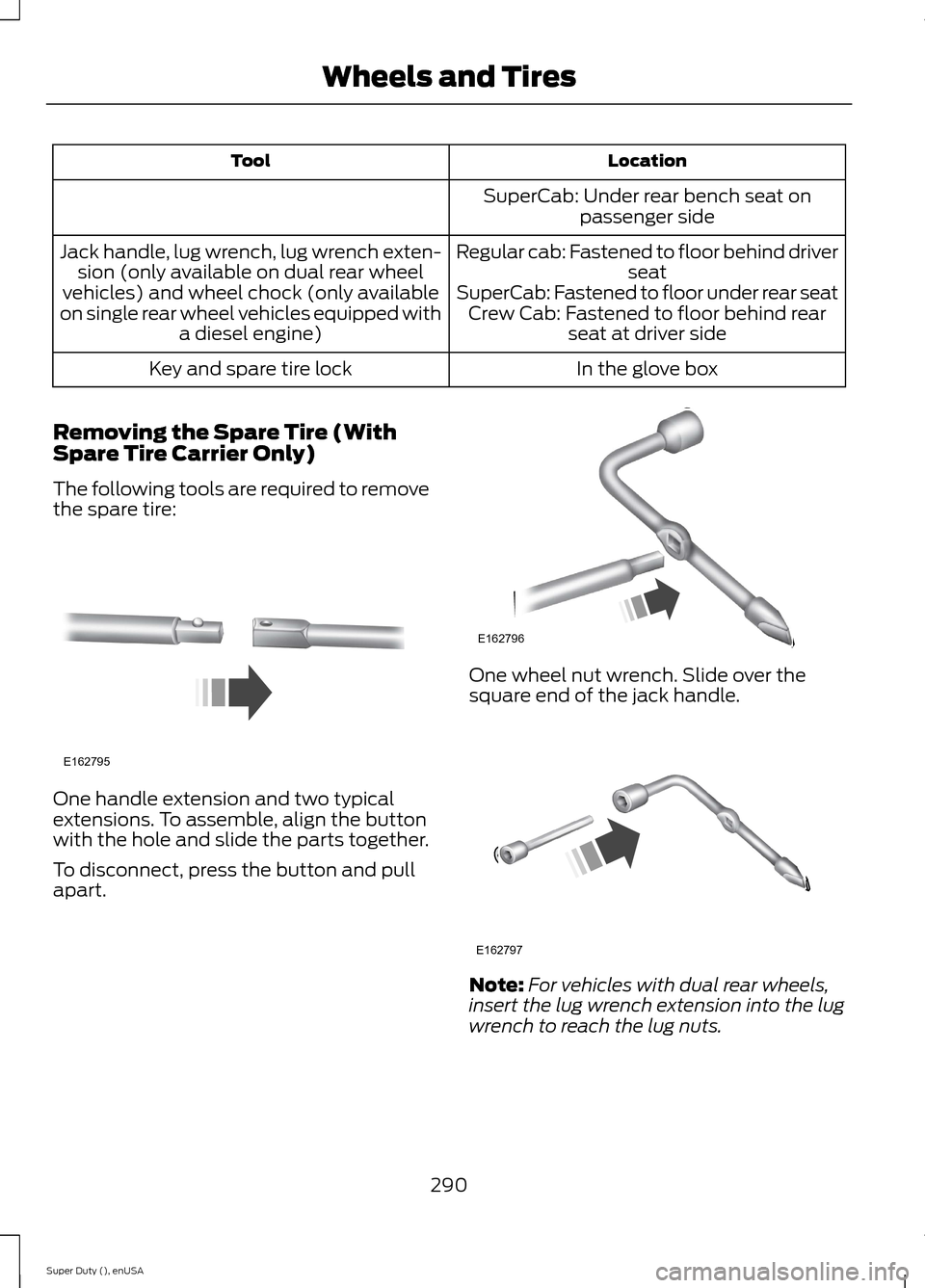
One handle extension and two typicalextensions. To assemble, align the buttonwith the hole and slide the parts together.
To disconnect, press the button and pullapart.
One wheel nut wrench. Slide over thesquare end of the jack handle.
Note:For vehicles with dual rear wheels,insert the lug wrench extension into the lugwrench to reach the lug nuts.
290Super Duty (), enUSAWheels and TiresE162795 E162796 E162797
Page 294 of 470
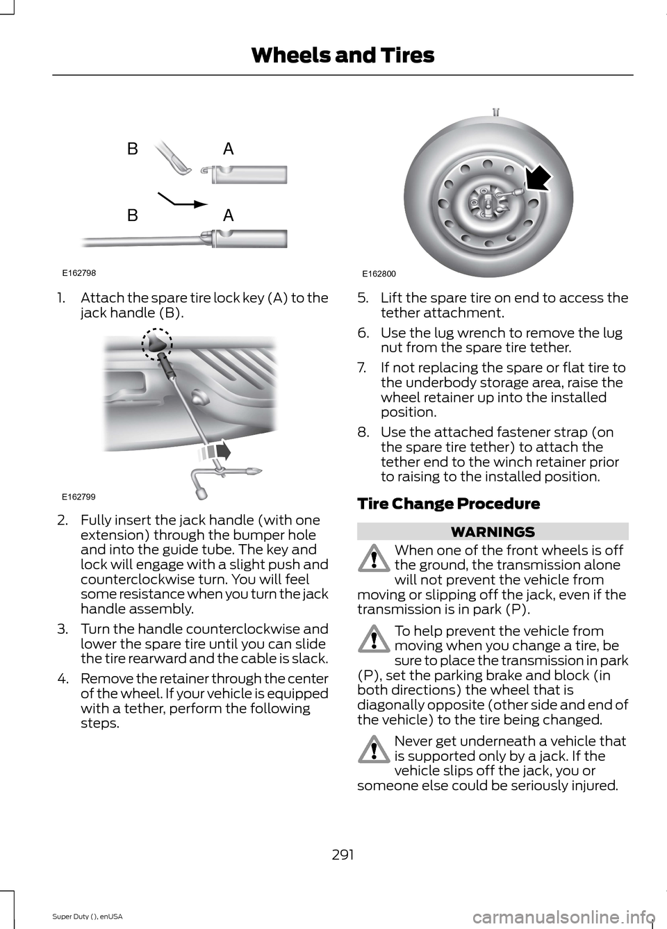
1.Attach the spare tire lock key (A) to thejack handle (B).
2.Fully insert the jack handle (with oneextension) through the bumper holeand into the guide tube. The key andlock will engage with a slight push andcounterclockwise turn. You will feelsome resistance when you turn the jackhandle assembly.
3.Turn the handle counterclockwise andlower the spare tire until you can slidethe tire rearward and the cable is slack.
4.Remove the retainer through the centerof the wheel. If your vehicle is equippedwith a tether, perform the followingsteps.
5.Lift the spare tire on end to access thetether attachment.
6.Use the lug wrench to remove the lugnut from the spare tire tether.
7.If not replacing the spare or flat tire tothe underbody storage area, raise thewheel retainer up into the installedposition.
8.Use the attached fastener strap (onthe spare tire tether) to attach thetether end to the winch retainer priorto raising to the installed position.
Tire Change Procedure
WARNINGS
When one of the front wheels is offthe ground, the transmission alonewill not prevent the vehicle frommoving or slipping off the jack, even if thetransmission is in park (P).
To help prevent the vehicle frommoving when you change a tire, besure to place the transmission in park(P), set the parking brake and block (inboth directions) the wheel that isdiagonally opposite (other side and end ofthe vehicle) to the tire being changed.
Never get underneath a vehicle thatis supported only by a jack. If thevehicle slips off the jack, you orsomeone else could be seriously injured.
291Super Duty (), enUSAWheels and TiresE162798ABAB E162799 E162800
Page 295 of 470
WARNINGS
Do not attempt to change a tire onthe side of the vehicle close tomoving traffic. Pull far enough off theroad to avoid the danger of being hit whenoperating the jack or changing the wheel.
Always use the jack provided asoriginal equipment with your vehicle.If using a jack other than the oneprovided as original equipment with yourvehicle, make sure the jack capacity isadequate for the vehicle weight, includingany vehicle cargo or modifications.
Note:Passengers should not remain in thevehicle when the vehicle is being jacked.
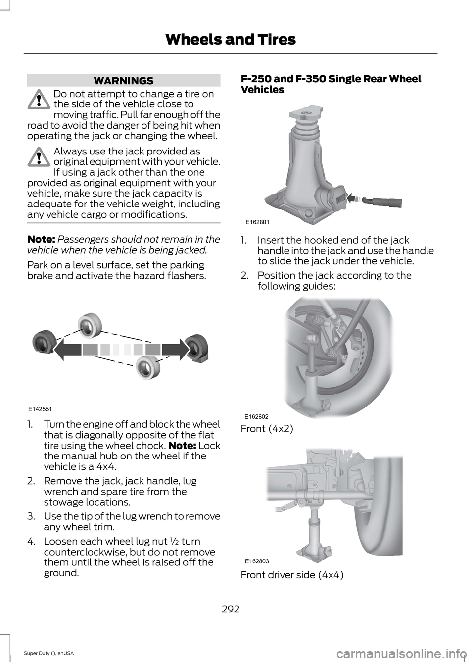
Park on a level surface, set the parkingbrake and activate the hazard flashers.
1.Turn the engine off and block the wheelthat is diagonally opposite of the flattire using the wheel chock.Note: Lockthe manual hub on the wheel if thevehicle is a 4x4.
2.Remove the jack, jack handle, lugwrench and spare tire from thestowage locations.
3.Use the tip of the lug wrench to removeany wheel trim.
4.Loosen each wheel lug nut ½ turncounterclockwise, but do not removethem until the wheel is raised off theground.
F-250 and F-350 Single Rear WheelVehicles
1.Insert the hooked end of the jackhandle into the jack and use the handleto slide the jack under the vehicle.
2.Position the jack according to thefollowing guides:
Front (4x2)
Front driver side (4x4)
292Super Duty (), enUSAWheels and TiresE142551 E162801 E162802 E162803
Page 296 of 470
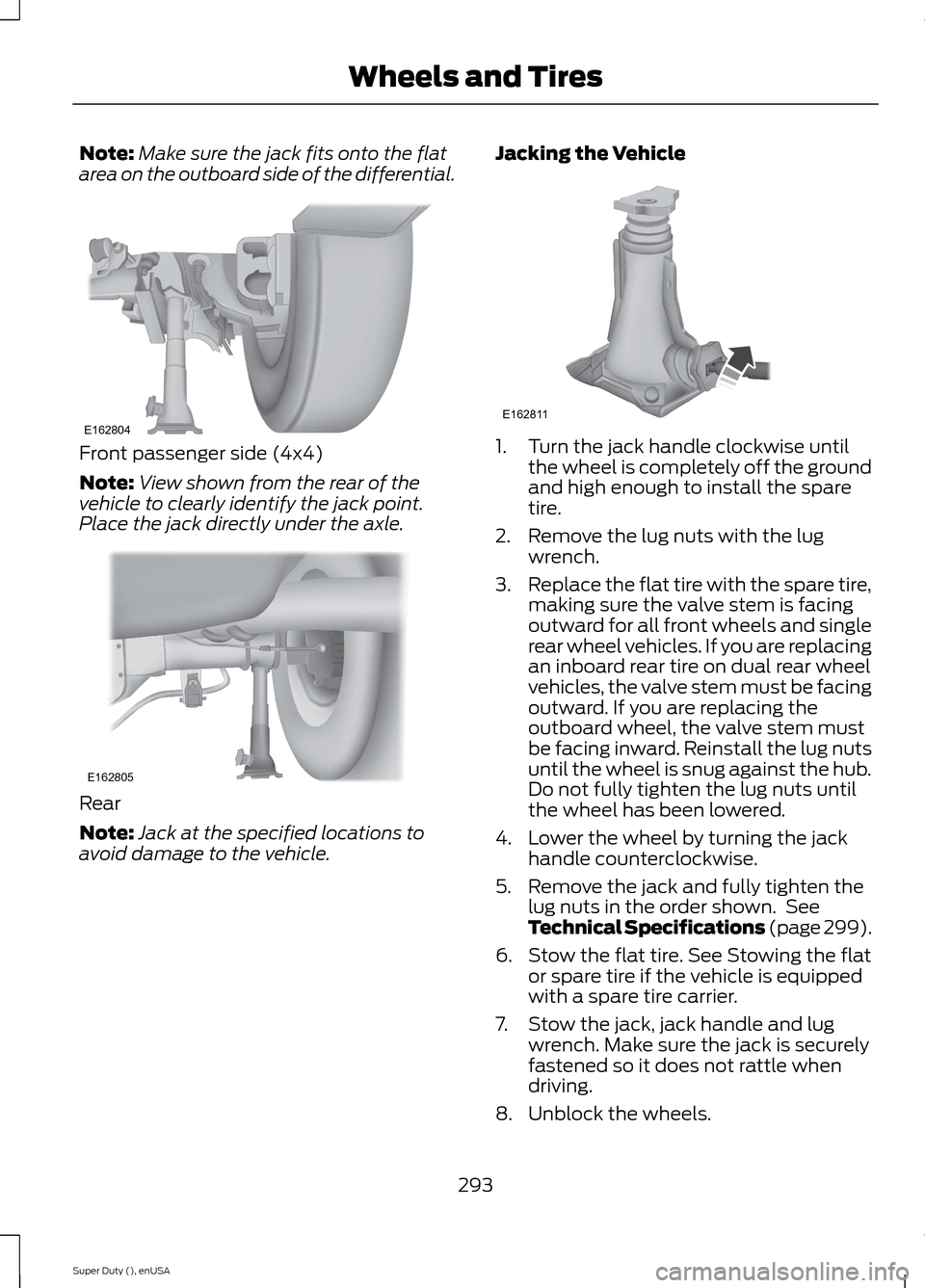
Note:Make sure the jack fits onto the flatarea on the outboard side of the differential.
Front passenger side (4x4)
Note:View shown from the rear of thevehicle to clearly identify the jack point.Place the jack directly under the axle.
Rear
Note:Jack at the specified locations toavoid damage to the vehicle.
Jacking the Vehicle
1.Turn the jack handle clockwise untilthe wheel is completely off the groundand high enough to install the sparetire.
2.Remove the lug nuts with the lugwrench.
3.Replace the flat tire with the spare tire,making sure the valve stem is facingoutward for all front wheels and singlerear wheel vehicles. If you are replacingan inboard rear tire on dual rear wheelvehicles, the valve stem must be facingoutward. If you are replacing theoutboard wheel, the valve stem mustbe facing inward. Reinstall the lug nutsuntil the wheel is snug against the hub.Do not fully tighten the lug nuts untilthe wheel has been lowered.
4.Lower the wheel by turning the jackhandle counterclockwise.
5.Remove the jack and fully tighten thelug nuts in the order shown. SeeTechnical Specifications (page 299).
6.Stow the flat tire. See Stowing the flator spare tire if the vehicle is equippedwith a spare tire carrier.
7.Stow the jack, jack handle and lugwrench. Make sure the jack is securelyfastened so it does not rattle whendriving.
8.Unblock the wheels.
293Super Duty (), enUSAWheels and TiresE162804 E162805 E162811
Page 297 of 470
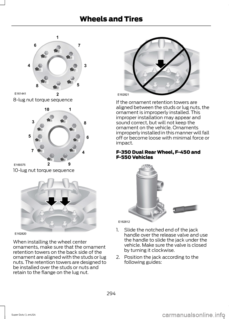
8-lug nut torque sequence
10-lug nut torque sequence
When installing the wheel centerornaments, make sure that the ornamentretention towers on the back side of theornament are aligned with the studs or lugnuts. The retention towers are designed tobe installed over the studs or nuts andretain to the flange on the lug nut.
If the ornament retention towers arealigned between the studs or lug nuts, theornament is improperly installed. Thisimproper installation may appear andsound correct, but will not keep theornament on the vehicle. Ornamentsimproperly installed in this manner will falloff or become loose with minimal force orimpact.
F-350 Dual Rear Wheel, F-450 andF-550 Vehicles
1.Slide the notched end of the jackhandle over the release valve and usethe handle to slide the jack under thevehicle. Make sure the valve is closedby turning it clockwise.
2.Position the jack according to thefollowing guides:
294Super Duty (), enUSAWheels and TiresE16144113427658 12345678910E169375 E162820 E162821 E162812