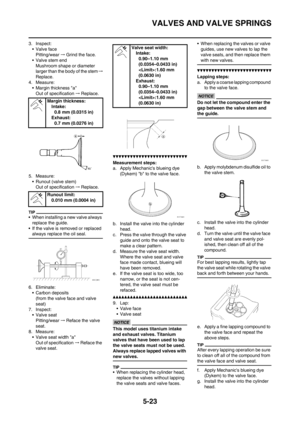
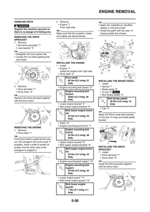
Page 185 of 230

6-18
FRONT FORK
HANDLING NOTE
Support the machine securely so
there is no danger of it falling over.
The front fork requires careful atten-
tion. So it is recommended that the
front fork be maintained at the deal-
ers.
To prevent an accidental explosion
of air, the following instructions
should be observed:
• The front fork with a built-in pis-
ton rod has a very sophisticated
internal construction and is par-
ticularly sensitive to foreign ma-
terial. Use enough care not to
allow any foreign material to
come in when the oil is replaced
or when the front fork is disas-
sembled and reassembled.
• Before removing the cap bolts or
front forks, be sure to extract the
air from the air chamber com-
pletely.
REMOVING THE FRONT FORK
CAP BOLT
1. Remove:
• Front fork cap bolt "1"
From the outer tube.
Before removing the front fork from
the machine, loosen the front fork cap
bolt.
2. Remove:
• Front fork cap bolt "1"
Hold the locknut "2" and remove the
front fork cap bolt.
REMOVING THE INNER TUBE
1. Remove:
• Dust seal "1"
• Stopper ring "2"
Using slotted-head screwdriver.
Take care not to scratch the inner
tube.
2. Remove:
• Inner tube "1"
Oil seal removal steps:
a. Push in slowly "a" the inner tube
just before it bottoms out and then
pull it back quickly "b".
b. Repeat this step until the inner
tube can be pulled out from the
outer tube.
REMOVING THE DAMPER ROD
1. Remove:
• Base valve "1"
• Damper rod "2"
Use a damper rod holder "3" to lock
the damper rod.
CHECKING THE DAMPER ROD
1. Inspect:
• Damper rod "1"
Bend/damage→Replace damper
rod.
The front fork with a built-in piston
rod has a very sophisticated inter-
nal construction and is particularly
sensitive to foreign material.
Use enough care not to allow any
foreign material to come in when
the oil is replaced or when the
front fork is disassembled and re-
assembled.
CHECKING THE BASE VALVE
1. Inspect:
• Valve assembly "1"
Wear/damage →Replace.
• O-ring "2"
Damage→ Replace.
CHECKING THE FORK SPRING
1. Measure:
• Fork spring free length "a"
Out of specification→Replace.
Damper rod holder:
YM-01494/90890-01494
Fork spring free length:
460.0 mm (18.11 in)
: 455.0 mm
(17.91 in)
Page 186 of 230

6-19
FRONT FORK
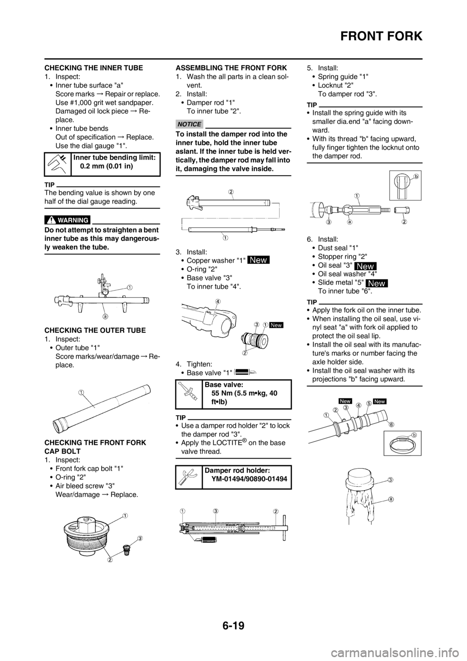
CHECKING THE INNER TUBE
1. Inspect:
• Inner tube surface "a"
Score marks→Repair or replace.
Use #1,000 grit wet sandpaper.
Damaged oil lock piece→Re-
place.
• Inner tube bends
Out of specification→Replace.
Use the dial gauge "1".
The bending value is shown by one
half of the dial gauge reading.
Do not attempt to straighten a bent
inner tube as this may dangerous-
ly weaken the tube.
CHECKING THE OUTER TUBE
1. Inspect:
• Outer tube "1"
Score marks/wear/damage→Re-
place.
CHECKING THE FRONT FORK
CAP BOLT
1. Inspect:
• Front fork cap bolt "1"
• O-ring "2"
• Air bleed screw "3"
Wear/damage→Replace.ASSEMBLING THE FRONT FORK
1. Wash the all parts in a clean sol-
vent.
2. Install:
• Damper rod "1"
To inner tube "2".
To install the damper rod into the
inner tube, hold the inner tube
aslant. If the inner tube is held ver-
tically, the damper rod may fall into
it, damaging the valve inside.
3. Install:
• Copper washer "1"
• O-ring "2"
• Base valve "3"
To inner tube "4".
4. Tighten:
• Base valve "1"
• Use a damper rod holder "2" to lock
the damper rod "3".
• Apply the LOCTITE
® on the base
valve thread.
5. Install:
• Spring guide "1"
• Locknut "2"
To damper rod "3".
• Install the spring guide with its
smaller dia.end "a" facing down-
ward.
• With its thread "b" facing upward,
fully finger tighten the locknut onto
the damper rod.
6. Install:
• Dust seal "1"
• Stopper ring "2"
• Oil seal "3"
• Oil seal washer "4"
• Slide metal "5"
To inner tube "6".
• Apply the fork oil on the inner tube.
• When installing the oil seal, use vi-
nyl seat "a" with fork oil applied to
protect the oil seal lip.
• Install the oil seal with its manufac-
ture's marks or number facing the
axle holder side.
• Install the oil seal washer with its
projections "b" facing upward.
Inner tube bending limit:
0.2 mm (0.01 in)
Base valve:
55 Nm (5.5 m•kg, 40
ft•lb)
Damper rod holder:
YM-01494/90890-01494
Page 187 of 230

6-20
FRONT FORK
7. Install:
• Piston metal "1"
Install the piston metal onto the slot
on inner tube.
8. Install:
• Outer tube "1"
To inner tube "2".
9. Install:
• Slide metal "1"
• Oil seal washer "2"
To outer tube slot.
Press the slide metal into the outer
tube with fork seal driver "3".
10. Install:
• Oil seal "1"
Press the oil seal into the outer tube
with fork seal driver "2".
11. Install:
• Stopper ring "1"
Fit the stopper ring correctly in the
groove in the outer tube.
12. Install:
• Dust seal "1"
Apply the lithium soap base grease
on the inner tube.
13. Check:
• Inner tube smooth movement
Tightness/binding/rough spots →
Repeat the steps 2 to 12.14. Compress the front fork fully.
15. Fill:
• Front fork oil
Until outer tube top surface with
recommended fork oil "1".
• Be sure to use recommended
fork oil. If other oils are used,
they may have an excessively ad-
verse effect on the front fork per-
formance.
• Never allow foreign materials to
enter the front fork.
16. After filling, pump the damper rod
"1" slowly up and down more than
10 times to distribute the fork oil.
17. Fill:
• Front fork oil
Until outer tube top surface with
recom-mended fork oil once
more.
18. After filling, pump the outer tube
"1" slowly up and down (about
200 mm (7.9 in) stroke) to distrib-
ute the fork oil once more.
Be careful not to excessive full stroke.
A stroke of 200 mm (7.9 in) or more
will cause air to enter. In this case, re-
peat the steps 15 to 18.
Fork seal driver:
YM-A0948/90890-01502
Fork seal driver:
YM-A0948/90890-01502
Recommended oil:
Suspension oil "S1"
Page 188 of 230

6-21
FRONT FORK
19. Wait ten minutes until the air bub-
bles have been removed from the
front fork, and the oil has dis-
pense evenly in system before
setting recommended oil level.
Fill with the fork oil up to the top end
of the outer tube, or the fork oil will not
spread over to every part of the front
forks, thus making it impossible to ob-
tain the correct level.
Be sure to fill with the fork oil up to the
top of the outer tube and bleed the
front forks.
20. Measure:
• Oil level (left and right) "a"
Out of specification→Adjust.
Be sure to install the spring guide "2"
when checking the oil level.
Never fail to make the oil level ad-
justment between the maximum
and minimum level and always ad-
just each front fork to the same
setting. Uneven adjustment can
cause poor handling and loss of
stability.
21. Measure:
• Distance "a"
Out of specification→Turn into
the locknut.
22. Loosen:
• Rebound damping adjuster "1"
• Loosen the rebound damping ad-
juster finger tight.
• Record the set position of the ad-
juster (the amount of turning out the
fully turned in position).
23. Install:
• Push rod "1"
• Fork spring "2"
• Install the fork spring with the
damper rod "3" pulled up.
• After installing the fork spring, hold
the damper rod end so that it will not
go down.
24. Install:
• Spring seat "1"
• Front fork cap bolt "2"
Fully finger tighten the front fork cap
bolt onto the damper rod.
25. Tighten:
• Front fork cap bolt (locknut) "1"
Hold the locknut "2" and tighten the
front fork cap bolt with specified
torque.
26. Install:
• Front fork cap bolt "1"
To outer tube.
Temporarily tighten the cap bolt.
27. Install:
• Protector guide "1"
Install the protector guide with its wid-
er side "a" facing downward.
Standard oil level:
132.0 mm (5.20 in)
Extent of adjustment:
95.0–150.0 mm (3.74–
5.91 in)
From top of outer tube
with inner tube and
damper rod "1" fully
compressed without
spring.
Distance "a":
18 mm (0.71 in) or more
Between damper rod
"1" top and locknut "2"
top.
Front fork cap bolt (lock-
nut):
29 Nm (2.9 m•kg, 21
ft•lb)
Page 189 of 230

6-22
FRONT FORK
INSTALLING THE FRONT FORK
1. Install:
• Front fork "1"
• Temporarily tighten the pinch bolts
(lower bracket).
• Do not tighten the pinch bolts (up-
per bracket) yet.
2. Tighten:
• Front fork cap bolt
3. Adjust:
• Front fork top end "a"
4. Tighten:
• Pinch bolt (upper bracket) "1"
• Pinch bolt (lower bracket) "2"
Tighten the lower bracket to speci-
fied torque. If torqued too much, it
may cause the front fork to mal-
function.
5. Install:
• Speed sensor lead "1"
•Plate 1 "2"
• Bolt (plate 1) "3"
To right protector "4".
Install the speed sensor lead so that
its paint "a" directs as shown and
align the bottom "b" of the plate 1 with
the same paint.
6. Install:
• Speed sensor lead "1"
•Plate 2 "2"
• Screw (plate 2) "3"
To right protector "4".
Install the plate 2 in the direction as
shown.
7. Install:
• Protector "1"
• Bolt (protector) "2"
8. Adjust:
• Rebound damping force
Turn in the damping adjuster "1" fin-
ger-tight and then turn out to the orig-
inally set position.
Front fork cap bolt:
30 Nm (3.0 m•kg, 22
ft•lb)
Front fork top end (stan-
dard) "a":
5 mm (0.20 in)
Pinch bolt (upper brack-
et):
21 Nm (2.1 m•kg, 15
ft•lb)
Pinch bolt (lower brack-
et):
21 Nm (2.1 m•kg, 15
ft•lb)
Bolt (plate 1):
4 Nm (0.4 m•kg, 2.9 ft •
lb)
Screw (plate 2):
0.5 Nm (0.05 m•kg, 0.36
ft•lb)
Bolt (protector):
7 Nm (0.7 m•kg, 5.1
ft•lb)
Page 190 of 230
6-23
HANDLEBAR
HANDLEBAR
REMOVING THE HANDLEBAR
Order Part name Q'ty Remarks
Headlight
1 Hot starter cable 1 Disconnect at the lever side.
2 Hot starter lever holder 1
3 Clutch cable 1 Disconnect at the lever side.
4 Clutch lever holder 1 Disconnect the clutch switch lead.
5 Engine stop switch 1 Disconnect the engine stop switch lead.
6 Brake master cylinder 1 Refer to removal section.
7 Start switch 1 Disconnect the start switch lead.
8 Throttle cable cap 1
9 Throttle cable #1 (pulled) 1 Disconnect at the throttle side.
10 Throttle cable #2 (pushed) 1 Disconnect at the throttle side.
11 Right grip 1 Refer to removal section.
12 Tube guide 1
13 Left grip 1 Refer to removal section.
14 Handlebar upper holder 2
15 Handlebar 1
16 Handlebar lower holder 2
Page 191 of 230

6-24
HANDLEBAR
REMOVING THE BRAKE MASTER
CYLINDER
1. Remove:
• Brake master cylinder bracket "1"
• Brake master cylinder "2"
• Do not let the brake master cylin-
der hang on the brake hose.
• Keep the brake master cylinder
cap side horizontal to prevent air
from coming in.
REMOVING THE GRIP
1. Remove:
•Grip "1"
Blow in air between the handlebar or
tube guide and the grip. Then remove
the grip which has become loose.
CHECKING THE HANDLEBAR
1. Inspect:
• Handlebar "1"
Bends/cracks/damage→Re-
place.
Do not attempt to straighten a bent
handlebar as this may dangerous-
ly weaken the handlebar.
INSTALLING THE HANDLEBAR
1. Install:
• Handlebar lower holder "1"
• Washer "2"
• Nut (handlebar lower holder) "3"
• Install the handlebar lower holder
with its side having the greater dis-
tance "a" from the mounting bolt
center facing forward.
• Apply the lithium soap base grease
on the thread of the handlebar low-
er holder.
• Installing the handlebar lower hold-
er in the reverse direction allows the
front-to-rear offset amount of the
handlebar position to be changed.
• Do not tighten the nut yet.
2. Install:
• Handlebar "1"
• Handlebar upper holder "2"
• Bolt (handlebar upper holder) "3"
• The handlebar upper holder should
be installed with the punched mark
"a" forward.
• Install the handlebar so that the
marks "b" are in place on both
sides.
• Install the handlebar so that the pro-
jection "c" of the handlebar upper
holder is positioned at the mark on
the handlebar as shown.
• First tighten the bolts on the front
side of the handlebar upper holder,
and then tighten the bolts on the
rear side.
3. Tighten:
• Nut (handlebar lower holder) "1"
4. Install:
• Left grip "1"
Apply the adhesive to the handle-
bar "2".
• Before applying the adhesive, wipe
off grease or oil on the handlebar
surface "a" with a lacquer thinner.
• Install the left grip to the handlebar
so that the line "b" between the two
arrow marks faces straight upward.
Bolt (handlebar upper
holder):
28 Nm (2.8 m•kg, 20
ft•lb)
Nut (handlebar lower
holder):
34 Nm (3.4 m•kg, 24
ft•lb)
Page 192 of 230

6-25
HANDLEBAR
5. Install:
• Right grip "1"
•Collar "2"
Apply the adhesive on the tube
guide "3".
• Before applying the adhesive, wipe
off grease or oil on the tube guide
surface "a" with a lacquer thinner.
• Install the grip to the tube guide so
that the grip match mark "b" and
tube guide slot "c" form the angle as
shown.
6. Install:
• Grip cap cover "1"
• Throttle grip "2"
Apply the lithium soap base grease
on the throttle grip sliding surface.
7. Install:
• Throttle cables "1"
To tube guide "2".
Apply the lithium soap base grease
on the throttle cable end and tube
guide cable winding portion.
8. Install:
• Throttle cable cap "1"
• Screw (throttle cable cap) "2"
After tightening the screws, check
that the throttle grip "3" moves
smoothly. If it does not, retighten
the bolts for adjustment.
9. Install:
• Grip cap cover "1"
• Cover (throttle cable cap) "2"10. Install:
• Start switch "1"
• Brake master cylinder "2"
• Brake master cylinder bracket "3"
• Bolt (brake master cylinder brack-
et) "4"
• Clamp "5"
• The start switch and brake master
cylinder bracket should be installed
according to the dimensions
shown.
• Install the bracket so that the arrow
mark "a" faces upward.
• First tighten the bolt on the upper
side of the brake master cylinder
bracket, and then tighten the bolt on
the lower side.
11. Install:
• Engine stop switch "1"
• Clutch lever holder "2"
• Bolt (clutch lever holder) "3"
Screw (throttle cable
cap):
4 Nm (0.4 m•kg, 2.9
ft•lb)
Start switch:
0.5 Nm (0.05 m•kg, 0.36
ft•lb)
Bolt (brake master cylin-
der bracket):
9 Nm (0.9 m•kg, 6.5
ft•lb)
Engine stop switch:
0.5 Nm (0.05 m•kg, 0.36
ft•lb)
Bolt (clutch lever holder):
4 Nm (0.4 m•kg, 2.9
ft•lb)