Page 73 of 230

1. Adjust:
• Pilot screw \"1\"
Adjustment steps:
To optimize the fuel flow at a smaller
throttle opening, each machines pilot
screw has been indi")
3-14
ENGINE
ADJUSTING THE PILOT SCREW
(For EUROPE)
1. Adjust:
• Pilot screw "1"
Adjustment steps:
To optimize the fuel flow at a smaller
throttle opening, each machine's pilot
screw has been individually set at the
factory. Before adjusting the pilot
screw, turn it in fully and count the
number of turns. Record this number
as the factory-set number of turns
out.
a. Turn in the pilot screw until it is
lightly seated.
b. Turn out the pilot screw by the
factory-set number of turns.
ADJUSTING THE ENGINE IDLING
SPEED
1. Start the engine and thoroughly
warm it up.
2. Adjust:
• Engine idling speed
Adjustment steps:
a. Turn the throttle stop screw "1"
until the specified engine idling
speed.
Using a digital engine tachometer for
idle speed adjustment, detect the en-
gine idling speed by bringing the
sensing element "c" of the engine ta-
chometer close to the ignition coil "2".
ADJUSTING THE VALVE
CLEARANCE
This section is intended for those who
have basic knowledge and skill con-
cerning the servicing of Yamaha mo-
torcycles (e.g., Yamaha dealers,
service engineers, etc.) Those who
have little knowledge and skill con-
cerning servicing are requested not to
undertake inspection, adjustment,
disassembly, or reassembly only by
reference to this manual. It may lead
to servicing trouble and mechanical
damage.
• The valve clearance should be ad-
justed when the engine is cool to
the touch.
• The piston must be at Top Dead
Center (T.D.C.) on compression
stroke to check or adjust the valve
clearance.
1. Remove:
•Seat
•Fuel tank
Refer to "SEAT, FUEL TANK
AND SIDE COVERS" section.
2. Drain:
• Coolant
Refer to "CHANGING THE
COOLANT" section.
3. Remove:
• Right radiator
Right to "RADIATOR" section in
the CHAPTER 5.
• Carburetor
Refer to "CARBURETOR" section
in the CHAPTER 5.
• Spark plug
• Upper engine bracket
• Cylinder head cover
Refer to "CAMSHAFTS" section
in the CHAPTER 5.4. Remove:
• Timing mark accessing screw "1"
• Crankshaft end accessing screw
"2"
• O-ring
5. Check:
• Valve clearance
Out of specification→Adjust.
Checking steps:
a. Turn the crankshaft counterclock-
wise with a wrench.
b. Align the T.D.C. mark "a" on the
rotor with the align mark "b" on the
crankcase cover when piston is at
T.D.C. on compression stroke.
In order to be sure that the piston is at
Top Dead Center, the punch mark "c"
on the exhaust camshaft and the
punch mark "d" on the intake cam-
shaft must align with the cylinder
head surface, as shown in the illustra-
tion.
c. Measure the valve clearance "e"
using a feeler gauge "1".
Record the measured reading if the
clearance is incorrect.
Pilot screw (example):
2 turns out
To increase idle speed→Turn the
throttle stop screw "1" in "a".
To decrease idle speed→Turn the
throttle stop screw "1" out "b".
Engine idling speed:
1,750–1,950 r/min
Valve clearance (cold):
Intake valve:
0.10–0.15 mm
(0.0039–0.0059 in)
Exhaust valve:
0.17–0.22 mm
(0.0067–0.0087 in)
Page 74 of 230
.
Refer to \"CAMSHAFTS\" section
in the CHAPTER 5.
b. Remove the valve lifters \"1\" and
the pads")
3-15
ENGINE
6. Adjust:
• Valve clearance
Adjustment steps:
a. Remove the camshaft (intake and
exhaust).
Refer to "CAMSHAFTS" section
in the CHAPTER 5.
b. Remove the valve lifters "1" and
the pads "2".
• Place a rag in the timing chain
space to prevent pads from falling
into the crankcase.
• Identity each valve lifter and pad
position very carefully so that they
can be reinstalled in their original
place.
c. Select the proper pad using the
pad selecting table.
The thickness "a" of each pad is indi-
cated in hundredths of millimeters on
the pad upper surface.
d. Round off the last digit of the in-
stalled pad number to the nearest
increment.
EXAMPLE:
Installed pad number = 148
Rounded off value = 150
Pads can only be selected in 0.05
mm increments.
e. Locate the rounded-off value and
the measured valve clearance in
the chart "PAD SELECTION TA-
BLE". The field where these two
coordinates intersect shows the
new pad number to use.
Use the new pad number only as a
guide when verifying the valve clear-
ance adjustment.
f. Install the new pads "3" and the
valve lifters "4".
• Apply the engine oil on the valve lift-
ers.
• Apply the molybdenum disulfide oil
on the valve stem ends.
• Valve lifter must turn smoothly
when rotated with a finger.
• Be careful to reinstall valve lifters
and pads in their original place.
g. Install the camshafts (exhaust
and intake).
Refer to "CAMSHAFTS" section
in the CHAPTER 5.
Pad rangePad Availabili-
ty: 25 incre-
ments
No.
120–
No.
2401.20
mm–
2.40
mmPads are avail-
able in 0.05 mm
increments
Last digit of pad
numberRounded valve
0, 1 or 2 0
4, 5 or 6 5
8 or 9 10
Page 75 of 230

3-16
ENGINE
INTAKE
EXHAUST
MEASURED
CLEARANCEINSTALLED PAD NUMBER
120 125 130 135 140 145 150 155 160 165 170
175 180 185 190 195 200 205 210 215 220 225 230 235 240
0.00 - 0.04 120 125 130 135 140 145 150 155
160165 170 175 180 185 190 195 200 205 210 215 220 225 230
0.05 - 0.09
120 125 130 135 140 145 150 155 160 165170 175 180 185 190 195 200 205 210 215 220 225 230 235
0.10 - 0.15
STANDARD CLEARANCE
0.16 - 0.20125130135140145150155160165170175180 185 190 195 200 205 210 215 220 225 230 235240
0.21 - 0.25130135140145150155160165170175180185 190 195 200 205 210 215 220 225 230 235240
0.26 - 0.30 135 140 145 150 155 160 165 170 175 180 185 190 195 200 205 210 215 220 225 230 235240
0.31 - 0.35 140 145 150 155 160 165 170 175 180 185 190 195 200 205 210 215 220 225 230 235240
0.36 - 0.40 145 150 155 160 165 170 175 180 185 190 195 200 205 210 215 220 225 230 235240
0.41 - 0.45 150 155 160 165 170 175 180 185 190 195 200 205 210 215 220 225 230 235240
0.46 - 0.50 155 160 165 170 175 180 185 190 195 200 205 210 215 220 225 230 235240
0.51 - 0.55 160 165 170 175 180 185 190 195 200 205 210 215 220 225 230 235240
0.56 - 0.60 165 170 175 180 185 190 195 200 205 210 215 220 225 230 235240
0.61 - 0.65 170 175 180 185 190 195 200 205 210 215 220 225 230 235240
0.66 - 0.70 175 180 185 190 195 200 205 210 215 220 225 230 235240
0.71 - 0.75 180 185 190 195 200 205 210 215 220 225 230 235240
0.76 - 0.80 185 190 195 200 205 210 215 220 225 230 235240VALVE CLEARANCE (cold):
0.10 - 0.15 mm
Example: Installed is 175
Measured clearance is 0.23 mm
Replace 175 pad with 185 pad
Pad number: (example)
Pad No. 175 = 1.75 mm
Pad No. 185 = 1.85 mm0.81 - 0.85 190 195 200 205 210 215 220 225 230 235240
0.86 - 0.90 195 200 205 210 215 220 225 230 235240
0.91 - 0.95 200 205 210 215 220 225 230 235240
0.96 - 1.00 205 210 215 220 225 230 235240
1.01 - 1.05 210 215 220 225 230 235240
1.06 - 1.10 215 220 225 230 235240
1.11 - 1.15 220 225 230 235240
1.16 - 1.20 225 230 235240
1.21 - 1.25 230 235240
1.26 - 1.30 235240
1.31 - 1.35 240
MEASURED
CLEARANCEINSTALLED PAD NUMBER
120 125 130 135 140 145 150 155 160 165 170
175 180 185 190 195 200 205 210 215 220 225 230 235 240
0.00 - 0.04 120 125 130 135 140 145 150 155
160 165 170 175 180 185 190 195 200 205 210 215 220 225
0.05 - 0.09
120 125 130 135 140 145 150 155 160165 170 175 180 185 190 195 200 205 210 215 220 225 230
0.10 - 0.16
120125130135140145150155160165170 175 180 185 190 195 200 205 210 215 220 225230235
0.17 - 0.22STANDARD CLEARANCE
0.23 - 0.25 125 130 135 140 145 150 155 160 165 170 175
180 185 190 195 200 205 210 215 220 225230235240
0.26 - 0.30130135140145150155160165170175180185 190 195 200 205 210 215 220 225230235240
0.31 - 0.35 135 140 145 150 155 160 165 170 175 180 185 190 195 200 205 210 215 220 225230235240
0.36 - 0.40 140 145 150 155 160 165 170 175 180 185 190 195 200 205 210 215 220 225230235240
0.41 - 0.45 145 150 155 160 165 170 175 180 185 190 195 200 205 210 215 220 225230235240
0.46 - 0.50 150 155 160 165 170 175 180 185 190 195 200 205 210 215 220 225230235240
0.51 - 0.55 155 160 165 170 175 180 185 190 195 200 205 210 215 220 225230235240
0.56 - 0.60 160 165 170 175 180 185 190 195 200 205 210 215 220 225230235240
0.61 - 0.65 165 170 175 180 185 190 195 200 205 210 215 220 225230235240
0.66 - 0.70 170 175 180 185 190 195 200 205 210 215 220 225230235240
0.71 - 0.75 175 180 185 190 195 200 205 210 215 220 225230235240
0.76 - 0.80 180 185 190 195 200 205 210 215 220 225230235240
0.81 - 0.85 185 190 195 200 205 210 215 220 225230235240
VALVE CLEARANCE (cold):
0.17 - 0.22 mm
Example: Installed is 175
Measured clearance is 0.27 mm
Replace 175 pad with 185 pad
Pad number: (example)
Pad No. 175 = 1.75 mm
Pad No. 185 = 1.85 mm0.86 - 0.90 190 195 200 205 210 215 220 225230235240
0.91 - 0.95 195 200 205 210 215 220 225230235240
0.96 - 1.00 200 205 210 215 220 225230235240
1.01 - 1.05 205 210 215 220 225230235240
1.06 - 1.10 210 215 220 225230235240
1.11 - 1.15 215 220 225230235240
1.16 - 1.20 220 225230235240
1.21 - 1.25 225230235240
1.26 - 1.30 230235240
1.31 - 1.35 235240
1.36 - 1.40 240
Page 76 of 230

3-17
CHASSIS
CHASSIS
BLEEDING THE HYDRAULIC
BRAKE SYSTEM
Bleed the brake system if:
• The system has been disassem-
bled.
• A brake hose has been loosened
or removed.
• The brake fluid is very low.
• The brake operation is faulty.
A dangerous loss of braking per-
formance may occur if the brake
system is not properly bled.
1. Remove:
• Brake master cylinder cap
• Diaphragm
• Reservoir float (front brake)
• Protector (rear brake)
2. Bleed:
• Brake fluid
Air bleeding steps:
a. Add proper brake fluid to the res-
ervoir.
b. Install the diaphragm. Be careful
not to spill any fluid or allow the
reservoir to overflow.
c. Connect the clear plastic tube "2"
tightly to the caliper bleed screw
"1".
A. Front
B. Rear
d. Place the other end of the tube
into a container.
e. Slowly apply the brake lever or
pedal several times.f. Pull the lever in or push down on
the pedal. Hold the lever or pedal
in position.
g. Loosen the bleed screw and allow
the lever or pedal to travel to-
wards its limit.
h. Tighten the bleed screw when the
lever or pedal limit has been
reached; then release the lever or
pedal.
i. Repeat steps (e) to (h) until of the
air bubbles have been removed
from the system.
If bleeding is difficult, it may be nec-
essary to let the brake fluid system
stabilize for a few hours. Repeat the
bleeding procedure when the tiny
bubbles in the system have disap-
peared.
j. Add brake fluid to the level line on
the reservoir.
Check the operation of the brake
after bleeding the brake system.
3. Install:
• Protector (rear brake)
• Reservoir float (front brake)
• Diaphragm
• Brake master cylinder cap
ADJUSTING THE FRONT BRAKE
1. Check:
• Brake lever position "a"2. Remove:
• Brake lever cover
3. Adjust:
• Brake lever position
Brake lever position adjustment
steps:
a. Loosen the locknut "1".
b. Turn the adjusting bolt "2" until the
lever position "a" is within speci-
fied position.
c. Tighten the locknut.
Be sure to tighten the locknut, as it
will cause poor brake perfor-
mance.
4. Install:
• Brake lever cover
ADJUSTING THE REAR BRAKE
1. Check:
• Brake pedal height "a"
Out of specification→Adjust.
Bleed screw:
6 Nm (0.6 m•kg, 4.3
ft•lb)
Brake lever position "a":
Standard posi-
tionExtent of ad-
justment
95 mm (3.74 in)76–97 mm
(2.99–3.82 in)
Locknut:
5 Nm (0.5 m •kg, 3.6
ft•lb)
Brake pedal height "a":
10.0 mm (0.39 in)
Page 77 of 230

3-18
CHASSIS
2. Adjust:
• Brake pedal height
Pedal height adjustment steps:
a. Loosen the locknut "1".
b. Turn the adjusting nut "2" until the
pedal height "a" is within specified
height.
c. Tighten the locknut.
• Adjust the pedal height between
the maximum "A" and the mini-
mum "B" as shown. (In this ad-
justment, the bolt "3" end "b"
should protrude out of the
threaded portion "4" but not be
less than 2 mm (0.08 in) "c" away
from the brake pedal "5").
• After the pedal height adjust-
ment, make sure that the rear
brake does not drag.
CHECKING AND REPLACING THE
FRONT BRAKE PADS
1. Inspect:
• Brake pad thickness "a"
Out of specification→Replace as
a set.2. Replace:
•Brake pad
Brake pad replacement steps:
a. Remove the pad pin plug "1".
b. Loosen the pad pin "2".
c. Remove the brake caliper "3"
from the front fork.
d. Remove the pad pin and brake
pads "4".
e. Connect the transparent hose "5"
to the bleed screw "6" and place
the suitable container under its
end.
f. Loosen the bleed screw and push
the brake caliper piston in.
Do not reuse the drained brake flu-
id.
g. Tighten the bleed screw.
h. Install the brake pads "7" and pad
pin.
• Install the brake pads with their pro-
jections "a" into the brake caliper re-
cesses "b".
• Temporarily tighten the pad pin at
this point.
i. Install the brake caliper "8" and
tighten the pad pin "9".
j. Install the pad pin plug "10".
Brake pad thickness:
4.4 mm (0.17 in)
: 1.0 mm (0.04
in)
Bleed screw:
6 Nm (0.6 m•kg, 4.3
ft•lb)
Bolt (brake caliper):
23 Nm (2.3 m•kg, 17
ft•lb)
Pad pin:
18 Nm (1.8 m•kg, 13
ft•lb)
Pad pin plug:
3 Nm (0.3 m•kg, 2.2
ft•lb)
Page 78 of 230

3-19
CHASSIS
3. Inspect:
• Brake fluid level
Refer to "CHECKING THE
BRAKE FLUID LEVEL" section.
4. Check:
• Brake lever operation
A softy or spongy feeling→Bleed
brake system.
Refer to "BLEEDING THE HY-
DRAULIC BRAKE SYSTEM" sec-
tion.
CHECKING AND REPLACING THE
REAR BRAKE PADS
1. Inspect:
• Brake pad thickness "a"
Out of specification→Replace as
a set.
2. Replace:
• Brake pad
Brake pad replacement steps:
a. Remove the protector "1" and pad
pin plug "2".
b. Loosen the pad pin "3".
c. Remove the rear wheel "4" and
brake caliper "5".
Refer to "FRONT WHEEL AND
REAR WHEEL" section in the
CHAPTER 6.d. Remove the pad pin "6" and brake
pads "7".
e. Connect the transparent hose "8"
to the bleed screw "9" and place
the suitable container under its
end.
f. Loosen the bleed screw and push
the brake caliper piston in.
Do not reuse the drained brake flu-
id.
g. Tighten the bleed screw.
h. Install the brake pad "10" and pad
pin "11".
• Install the brake pads with their pro-
jections "a" into the brake caliper re-
cesses "b".
• Temporarily tighten the pad pin at
this point.
i. Install the brake caliper "12" and
rear wheel "13".
Refer to "FRONT WHEEL AND
REAR WHEEL" section in the
CHAPTER 6.j. Tighten the pad pin "14".
k. Install the pad pin plug "15" and
protector "16".
3. Inspect:
• Brake fluid level
Refer to "CHECKING THE
BRAKE FLUID LEVEL" section.
4. Check:
• Brake pedal operation
A softy or spongy feeling→Bleed
brake system.
Refer to "BLEEDING THE HY-
DRAULIC BRAKE SYSTEM" sec-
tion.
CHECKING THE REAR BRAKE
PAD INSULATOR
1. Remove:
• Brake pad
Refer to "CHECKING AND RE-
PLACING THE REAR BRAKE
PADS" section.
2. Inspect:
• Rear brake pad insulator "1"
Damage→Replace. Brake pad thickness:
6.4 mm (0.25 in)
: 1.0 mm (0.04
in)
Bleed screw:
6 Nm (0.6 m•kg, 4.3
ft•lb)
Pad pin:
18 Nm (1.8 m•kg, 13
ft•lb)
Pad pin plug:
3 Nm (0.3 m•kg, 2.2
ft•lb)
Bolt (protector):
7 Nm (0.7 m•kg, 5.1
ft•lb)
Page 79 of 230

3-20
CHASSIS
CHECKING THE BRAKE FLUID
LEVEL
1. Place the brake master cylinder
so that its top is in a horizontal po-
sition.
2. Inspect:
• Brake fluid level
Fluid at lower level→Fill up.
• Use only designated quality
brake fluid to avoid poor brake
performance.
• Refill with same type and brand
of brake fluid; mixing fluids
could result in poor brake perfor-
mance.
• Be sure that water or other con-
taminants do not enter master
cylinder when refilling.
• Clean up spilled fluid immediate-
ly to avoid erosion of painted
surfaces or plastic parts.
a. Lower level
A. Front
B. Rear
CHECKING THE SPROCKET
1. Inspect:
• Sprocket teeth "a"
Excessive wear→Replace.
Replace the drive sprocket, rear
wheel sprocket and drive chain as a
set.
CHECKING THE DRIVE CHAIN
1. Measure:
• Drive chain length (15 links) "a"
Out of specification→Replace.
• While measuring the drive chain
length, push down on the drive
chain to increase its tension.
• Measure the length between drive
chain roller "1" and "16" as shown.
• Perform this measurement at two or
three different places.
2. Remove:
• Drive chain "1"
Remove the drive chain using a drive
chain cutter "2".
3. Clean:
• Drive chain
Brush off as much dirt as possi-
ble. Then clean the drive chain
using the chain cleaner.
This machine has a drive chain
with small rubber O-rings "1" be-
tween the side plates. Steam
cleaning, high-pressure washes,
certain solvent and kerosene can
damage these O-rings.
4. Inspect:
• O-ring "1" (drive chain)
Damage→Replace the drive
chain.
•Roller "2"
• Side plate "3"
Damage/wear→Replace the
drive chain.
5. Check:
• Drive chain stiffness "a"
Clean and oil the drive chain and
hold as illustrated.
Stiff→Replace the drive chain.
6. Install:
• Chain joint "1"
• O-ring "2"
• Drive chain "3"
• Link plate "4"
When installing the drive chain, apply
the lithium soap base grease on the
chain joint and O-rings.
7. Install:
• Link plate
• Press the link plate onto the chain
joint using a drive chain riveter "5".
• Rivet the end of the chain joint us-
ing a drive chain riveter.
• After riveting the chain joint, make
sure its movement is smooth.
Recommended brake flu-
id:
DOT #4
Drive chain length (15
links):
: 239.3 mm
(9.42 in)
Page 80 of 230

3-21
CHASSIS
8. Lubricate:
• Drive chain
ADJUSTING THE DRIVE CHAIN
SLACK
1. Elevate the rear wheel by placing
the suitable stand under the en-
gine.
2. Check:
• Drive chain slack "a"
Above the seal guard installation
bolt.
Out of specification→Adjust.
Before checking and/or adjusting, ro-
tate the rear wheel through several
revolutions and check the slack sev-
eral times to find the tightest point.
Check and/or adjust the drive chain
slack with the rear wheel in this "tight
chain" position.
3. Adjust:
• Drive chain slack
Drive chain slack adjustment
steps:
a. Loosen the axle nut "1" and lock-
nuts "2".b. Adjust the drive chain slack by
turning the adjusters "3".
c. Turn each adjuster exactly the
same amount to maintain correct
axle alignment. (There are marks
"a" on each side of the drive chain
puller alignment.) NOTICE: Im-
proper drive chain slack will
overload the engine as well as
other vital parts of the motorcy-
cle and can lead to chain slip-
page or breakage. To prevent
this from occurring, keep the
drive chain slack within the
specified limits.
Turn the adjuster so that the drive
chain is in line with the sprocket, as
viewed from the rear.
d. Tighten the axle nut while pushing
down the drive chain.
e. Tighten the locknuts.
CHECKING THE FRONT FORK
1. Inspect:
• Front fork smooth action
Operate the front brake and
stroke the front fork.
Unsmooth action/oil leakage→
Repair or replace.CLEANING THE FRONT FORK OIL
SEAL AND DUST SEAL
1. Remove:
•Protector
• Dust seal "1"
Use a thin screw driver, and be care-
ful not to damage the inner fork tube
and dust seal.
2. Clean:
• Dust seal "a"
• Oil seal "b"
• Clean the dust seal and oil seal af-
ter every run.
• Apply the lithium soap base grease
on the inner tube.
RELIEVING THE FRONT FORK
INTERNAL PRESSURE
If the front fork initial movement feels
stiff during a run, relieve the front fork
internal pressure.
1. Elevate the front wheel by placing
a suitable stand under the engine.
2. Remove the air bleed screw "1"
and release the internal pressure
from the front fork.
3. Install:
• Air bleed screw Drive chain lubricant:
SAE 10W-40 motor oil
or suitable chain lubri-
cants
Drive chain slack:
48.0–58.0 mm (1.89–
2.28 in)
To tighten→Turn the adjuster "3"
counterclockwise.
To loosen→Turn the adjuster "3"
clockwise and push wheel for-
ward.
Axle nut:
125 Nm (12.5 m•kg, 90
ft•lb)
Locknut:
19 Nm (1.9 m•kg, 13
ft•lb)
Air bleed screw:
1 Nm (0.1 m•kg, 0.7
ft•lb)
 1
1 2
2 3
3 4
4 5
5 6
6 7
7 8
8 9
9 10
10 11
11 12
12 13
13 14
14 15
15 16
16 17
17 18
18 19
19 20
20 21
21 22
22 23
23 24
24 25
25 26
26 27
27 28
28 29
29 30
30 31
31 32
32 33
33 34
34 35
35 36
36 37
37 38
38 39
39 40
40 41
41 42
42 43
43 44
44 45
45 46
46 47
47 48
48 49
49 50
50 51
51 52
52 53
53 54
54 55
55 56
56 57
57 58
58 59
59 60
60 61
61 62
62 63
63 64
64 65
65 66
66 67
67 68
68 69
69 70
70 71
71 72
72 73
73 74
74 75
75 76
76 77
77 78
78 79
79 80
80 81
81 82
82 83
83 84
84 85
85 86
86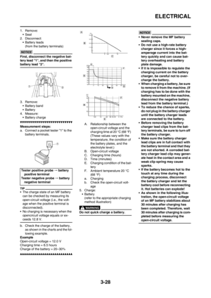 87
87 88
88 89
89 90
90 91
91 92
92 93
93 94
94 95
95 96
96 97
97 98
98 99
99 100
100 101
101 102
102 103
103 104
104 105
105 106
106 107
107 108
108 109
109 110
110 111
111 112
112 113
113 114
114 115
115 116
116 117
117 118
118 119
119 120
120 121
121 122
122 123
123 124
124 125
125 126
126 127
127 128
128 129
129 130
130 131
131 132
132 133
133 134
134 135
135 136
136 137
137 138
138 139
139 140
140 141
141 142
142 143
143 144
144 145
145 146
146 147
147 148
148 149
149 150
150 151
151 152
152 153
153 154
154 155
155 156
156 157
157 158
158 159
159 160
160 161
161 162
162 163
163 164
164 165
165 166
166 167
167 168
168 169
169 170
170 171
171 172
172 173
173 174
174 175
175 176
176 177
177 178
178 179
179 180
180 181
181 182
182 183
183 184
184 185
185 186
186 187
187 188
188 189
189 190
190 191
191 192
192 193
193 194
194 195
195 196
196 197
197 198
198 199
199 200
200 201
201 202
202 203
203 204
204 205
205 206
206 207
207 208
208 209
209 210
210 211
211 212
212 213
213 214
214 215
215 216
216 217
217 218
218 219
219 220
220 221
221 222
222 223
223 224
224 225
225 226
226 227
227 228
228 229
229