Page 25 of 84

INSTRUMENT AND CONTROL FUNCTIONS
3-9
3
EAUS1963
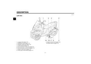
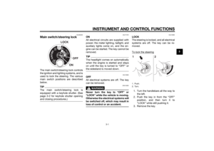
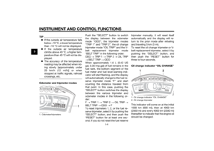
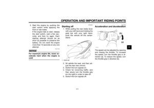
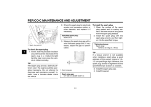
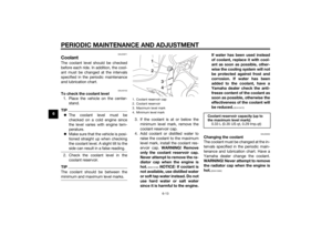
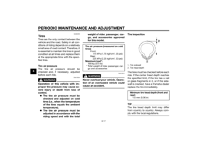
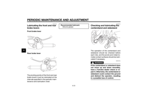
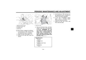
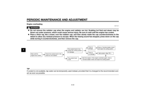
Rear brake leverThe rear brake lever is located on the
left handlebar grip. To apply the rear
brake, pull the lever toward the handle-
bar grip.
This model is equipped with a unified
brake system.
When pulling the rear brake lever, the
rear brake and a portion of the front
brake are applied. For full braking per-
formance, apply both brake levers si-
multaneously.
TIP As the unified brake system is me-
chanical, additional free play can
be felt in the front brake lever
when the rear brake lever is being
pulled.
The unified brake system does not
function when the front brake is
applied alone.
EAU37473
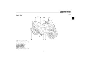
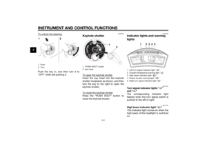
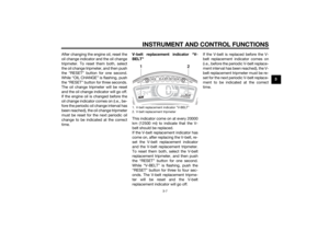
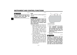
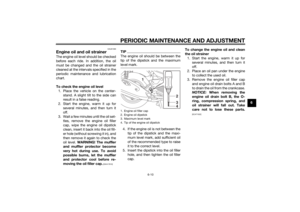
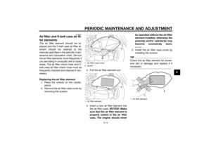
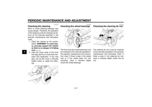
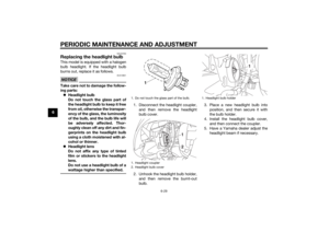
Fuel tank capTo remove the fuel tank cap
1. Open the seat. (See page 3-12.)
2. Turn the fuel tank cap counter- clockwise and pull it off.
To install the fuel tank cap 1. Insert the fuel tank cap into the tank opening and turn it clockwise
until the “ ” marks on the cap
and tank are aligned.
2. Close the seat.
1. Rear brake lever
1
1. Fuel tank cap
2. “ ” mark
2
2
1
U2CME0E0.book Page 9 Friday, May 2, 2014 2:55 PM
Page 26 of 84

INSTRUMENT AND CONTROL FUNCTIONS
3-10
3
WARNING
EWA11092
Make sure that the fuel tank cap is
properly closed after fillin g fuel.
Leakin g fuel is a fire hazar d.
EAU13222
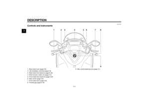
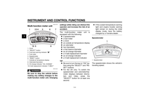
FuelMake sure there is sufficient gasoline in
the tank.
WARNING
EWA10882
Gasoline an d g asoline vapors are
extremely flamma ble. To avoi d fires
an d explosions an d to re duce the
risk of injury when refuelin g, follow
these instructions.1. Before refueling, turn off the en- gine and be sure that no one is sit-
ting on the vehicle. Never refuel
while smoking, or while in the vi-
cinity of sparks, open flames, or
other sources of ignition such as
the pilot lights of water heaters
and clothes dryers.
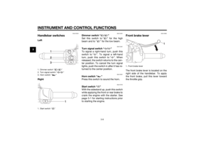
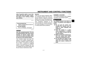
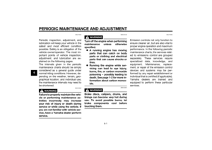
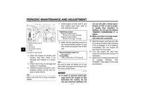
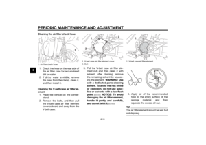
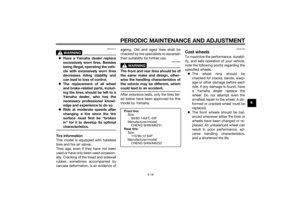
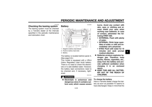
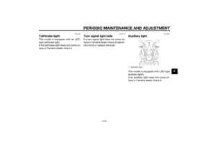
2. Do not overfill the fuel tank. When refueling, be sure to insert the
pump nozzle into the fuel tank filler
hole. Stop filling when the fuel
reaches the bottom of the filler
tube. Because fuel expands when
it heats up, heat from the engine or
the sun can cause fuel to spill out
of the fuel tank. 3. Wipe up any spilled fuel immedi-
ately. NOTICE: Immediately
wipe off spille d fuel with a clean,
d ry, soft cloth, since fuel may
d eteriorate painted surfaces or
plastic parts.
[ECA10072]
4. Be sure to securely close the fuel tank cap.
WARNING
EWA15152
Gasoline is poisonous an d can
cause injury or death. Han dle gaso-
line with care. Never siphon gasoline
b y mouth. If you shoul d swallow
some gasoline or inhale a lot of g as-
oline vapor, or g et some gasoline in
your eyes, see your doctor imme di-1. Fuel tank filler tube
2. Maximum fuel level
1
2
U2CME0E0.book Page 10 Friday, May 2, 2014 2:55 PM
Page 27 of 84

INSTRUMENT AND CONTROL FUNCTIONS
3-11
3
ately. If g
asoline spills on your skin,
wash with soap an d water. If gaso-
line spills on your clothin g, chan ge
your clothes.
EAU53012
NOTICE
ECA11401
Use only unlea ded g asoline. The use
of lead ed g asoline will cause severe
d amag e to internal en gine parts,
such as the valves an d piston rin gs,
as well as to the exhaust system.Your Yamaha engine has been de-
signed to use regular unleaded gaso-
line with a research octane number of
95 or higher. If knocking (or pinging)
occurs, use a gasoline of a different
brand or premium unleaded fuel. Use
of unleaded fuel will extend spark plug
life and reduce maintenance costs. Gasohol
There are two types of gasohol: gaso-
hol containing ethanol and that con-
taining methanol. Gasohol containing
ethanol can be used if the ethanol con-
tent does not exceed 10% (E10). Gas-
ohol containing methanol is not
recommended by Yamaha because it
can cause damage to the fuel system
or vehicle performance problems.
EAU13434
Catalytic converterThis model is equipped with a catalytic
converter in the exhaust system.
WARNING
EWA10863
The exhaust system is hot after op-
eration. To prevent a fire hazar
d or
b urns:
Do not park the vehicle near
possi ble fire hazar ds such as
g rass or other materials that
easily burn.
Park the vehicle in a place
where pe destrians or chil dren
are not likely to touch the hot
exhaust system.
Make sure that the exhaust sys-
tem has coole d down before
d oin g any maintenance work.
Do not allow the en gine to i dle
more than a few minutes. Lon g
i d lin g can cause a b uild-up of
heat.
Recommen ded fuel:
Regular unleaded gasoline (Gasohol
(E10) acceptable)
Fuel tank capacity:
6.6 L (1.74 US gal, 1.45 Imp.gal)
U2CME0E0.book Page 11 Friday, May 2, 2014 2:55 PM
Page 28 of 84
INSTRUMENT AND CONTROL FUNCTIONS
3-12
3
NOTICE
ECA10702
Use only unleaded g asoline. The use
of lead ed g asoline will cause unre-
pairab le damag e to the catalytic
converter.
EAU60620
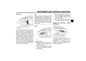
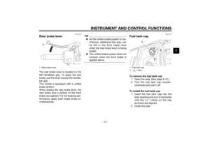
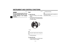
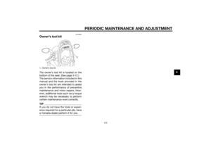
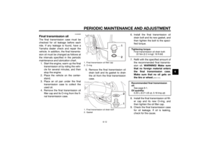
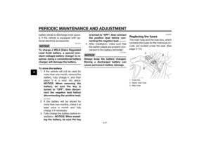
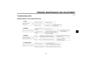
SeatTo open the seat 1. Place the vehicle on the center- stand.
2. Insert the key into the main switch, and then turn it counterclockwise
to “SEAT OPEN”.TIPDo not push inward when turning the
key.3. Fold the seat up.
To close the seat 1. Fold the seat down, and then push it down to lock it in place. 2. Remove the key.
TIPMake sure that the seat is properly se-
cured before riding.
1. Open.
1
U2CME0E0.book Page 12 Friday, May 2, 2014 2:55 PM
Page 29 of 84

INSTRUMENT AND CONTROL FUNCTIONS
3-13
3
EAUT3711
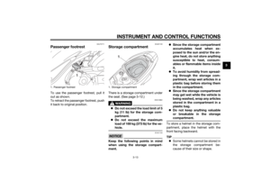
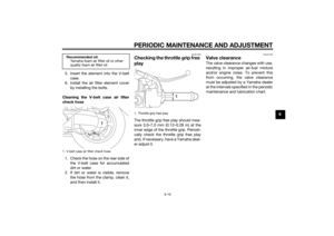
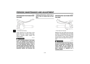
Passenger footrestTo use the passenger footrest, pull it
out as shown.
To retract the passenger footrest, push
it back to original position.
EAU61130
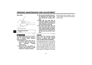
Stora ge compartmentThere is a storage compartment under
the seat. (See page 3-12.)
WARNING
EWA10962
Do not exceed the load limit of 5
k g (11 l b) for the stora ge com-
partment.
Do not exceed the maximum
loa d of 169 k g (373 l b) for the ve-
hicle.NOTICE
ECA21150
Keep the followin g points in min d
when usin g the stora ge compart-
ment.
Since the storag e compartment
accumulates heat when ex-
pose d to the sun an d/or the en-
g ine heat, d o not store anythin g
suscepti ble to heat, consum-
a b les or flamma ble items insi de
it.
To avoi d humi dity from sprea d-
in g throu gh the stora ge com-
partment, wrap wet articles in a
plastic bag b efore storin g them
in the compartment.
Since the storag e compartment
may get wet while the vehicle is
b ein g washe d, wrap any articles
store d in the compartment in a
plastic bag .
Do not keep anythin g valua ble
or breakab le in the stora ge
compartment.
To store a helmet in the storage com-
partment, place the helmet with the
front facing backward.TIP Some helmets cannot be stored in
the storage compartment be-
cause of their size or shape.
1. Passenger footrest
1
1. Storage compartment
1
U2CME0E0.book Page 13 Friday, May 2, 2014 2:55 PM
Page 30 of 84

INSTRUMENT AND CONTROL FUNCTIONS
3-14
3
Do not leave your vehicle unat-
tended with the seat open.
EAU61380
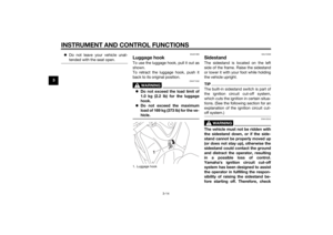
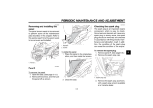
Lugga ge hookTo use the luggage hook, pull it out as
shown.
To retract the luggage hook, push it
back to its original position.
WARNING
EWAT1032
Do not exceed the load limit of
1.0 k g (2.2 l b) for the lu ggage
hook.
Do not exceed the maximum
loa d of 169 k g (373 l b) for the ve-
hicle.
EAU15306
Si destan dThe sidestand is located on the left
side of the frame. Raise the sidestand
or lower it with your foot while holding
the vehicle upright.TIPThe built-in sidestand switch is part of
the ignition circuit cut-off system,
which cuts the ignition in certain situa-
tions. (See the following section for an
explanation of the ignition circuit cut-
off system.)
WARNING
EWA10242
The vehicle must not be ri dden with
the si destan d d own, or if the si de-
stan d cannot b e properly moved up
(or does not stay up), otherwise the
si destan d coul d contact the groun d
an d d istract the operator, resultin g
in a possi ble loss of control.
Yamaha’s i gnition circuit cut-off
system has been desi gne d to assist
the operator in fulfillin g the respon-
si bility of raisin g the si destan d b e-
fore startin g off. Therefore, check
1. Luggage hook
1
U2CME0E0.book Page 14 Friday, May 2, 2014 2:55 PM
Page 31 of 84
INSTRUMENT AND CONTROL FUNCTIONS
3-15
3
this system re
gularly an d have a
Yamaha dealer repair it if it does not
function properly.
EAUT1096
I g nition circuit cut-off systemCheck the operation of the sidestand
switch according to the following pro-
cedure.
U2CME0E0.book Page 15 Friday, May 2, 2014 2:55 PM
Page 32 of 84
INSTRUMENT AND CONTROL FUNCTIONS
3-16
3
Turn the key on.
Put the sidestand up.Push the start switch while applying
either of the brake levers. The engine will
start.Put the sidestand down.
If the engine stalls:
The sidestand switch is OK.
• The vehicle must be placed on the center-
stand during this inspection.• If a malfunction is noted, have a Yamaha
dealer check the system before riding.
WARNING
U2CME0E0.book Page 16 Friday, May 2, 2014 2:55 PM