Page 49 of 84

PERIODIC MAINTENANCE AND ADJUSTMENT
6-10
6
EAU61000
Engine oil an d oil strainerThe engine oil level should be checked
before each ride. In addition, the oil
must be changed and the oil strainer
cleaned at the intervals specified in the
periodic maintenance and lubrication
chart.
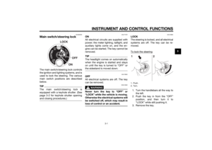
To check the en gine oil level
1. Place the vehicle on the center- stand. A slight tilt to the side can
result in a false reading.
2. Start the engine, warm it up for several minutes, and then turn it
off.
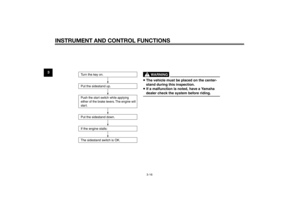
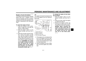
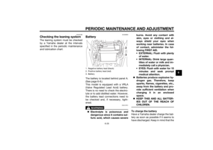
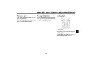
3. Wait a few minutes until the oil set- tles, remove the engine oil filler
cap, wipe the engine oil dipstick
clean, insert it back into the oil fill-
er hole (without screwing it in), and
then remove it again to check the
oil level. WARNING! The muffler
an d muffler protector become
very hot d uring use. To avoi d
possi ble burns, let the muffler
an d protector cool b efore re-
movin g the oil filler cap.
[EWA17810]
TIPThe engine oil should be between the
tip of the dipstick and the maximum
level mark.4. If the engine oil is not between the
tip of the dipstick and the maxi-
mum level mark, add sufficient oil
of the recommended type to raise
it to the correct level.
5. Insert the dipstick into the oil filler hole, and then tighten the oil filler
cap. To chan
ge the en gine oil an d clean
the oil strainer 1. Start the engine, warm it up for several minutes, and then turn it
off.
2. Place an oil pan under the engine to collect the used oil.
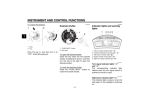
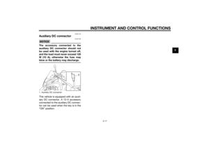
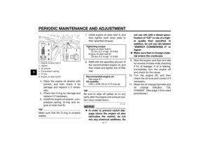
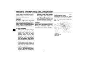
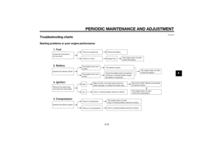
3. Remove the engine oil filler cap and engine oil drain bolts A and B
to drain the oil from the crankcase.
NOTICE: When removin g the
en gine oil drain bolt B, the O-
rin g, compression spring , and
oil strainer will fall out. Take
care not to lose these parts.
[ECAT1022]
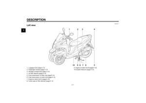
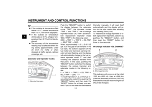
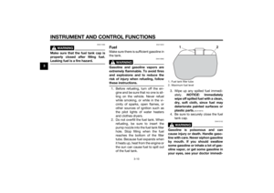
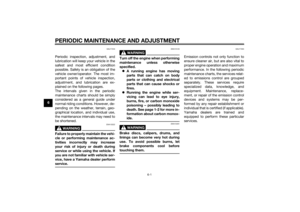
1. Engine oil filler cap
2. Engine oil dipstick
3. Maximum level mark
4. Tip of the engine oil dipstick
1
234
U2CME0E0.book Page 10 Friday, May 2, 2014 2:55 PM
Page 50 of 84

PERIODIC MAINTENANCE AND ADJUSTMENT
6-11
64. Clean the engine oil strainer withsolvent, and then check it for
damage and replace it if neces-
sary.
5. Check the O-ring for damage and replace it if necessary.
6. Install the engine oil strainer, com- pression spring, O-ring and en-
gine oil drain bolt B.
TIPMake sure that the O-ring is properly
seated.
7. Install engine oil drain bolt A, andthen tighten both drain bolts to
their specified torques.
8. Refill with the specified amount of the recommended engine oil, and
then install and tighten the oil filler
cap.TIPBe sure to wipe off spilled oil on any
parts after the engine and exhaust sys-
tem have cooled down.NOTICE
ECA11621
In or der to prevent clutch slip-
pa ge (since the en gine oil also
lu bricates the clutch), do not
mix any chemical additives. Do not use oils with a
diesel speci-
fication of “CD” or oils of a hi gh-
er quality than specifie d. In
a ddition, do not use oils la beled
“ENERGY CONSERVING II” or
hi gher.
Make sure that no forei gn mate-
rial enters the crankcase.
9. Start the engine, and then let it idle for several minutes while checking
it for oil leakage. If oil is leaking,
immediately turn the engine off
and check for the cause.
10. Turn the engine off, and then check the oil level and correct it if
necessary.
11. Reset the oil change tripmeter and oil change indicator “OIL
CHANGE”. (See page 3-6 for reset
procedures.)
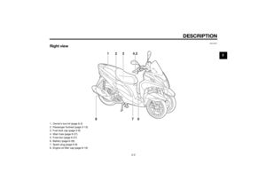
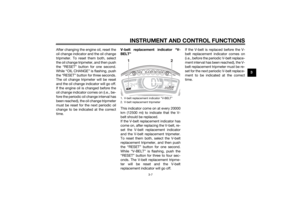
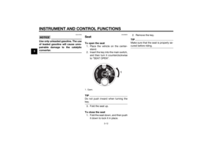
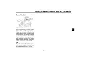
1. Engine oil drain bolt A
2. Gasket
3. Oil strainer
4. Compression spring
5. O-ring
6. Engine oil drain bolt B
1
3456
2
Tightenin g torque:
Engine oil drain bolt A: 22 Nm (2.2 m·kgf, 16 ft·lbf)
Engine oil drain bolt B:
20 Nm (2.0 m·kgf, 14 ft·lbf)
Recommen ded en gine oil:
See page 8-1.
Oil quantity: 0.80 L (0.85 US qt, 0.70 Imp.qt)
U2CME0E0.book Page 11 Friday, May 2, 2014 2:55 PM
Page 51 of 84

PERIODIC MAINTENANCE AND ADJUSTMENT
6-12
6
EAU60660
Final transmission oilThe final transmission case must be
checked for oil leakage before each
ride. If any leakage is found, have a
Yamaha dealer check and repair the vehicle. In addition, the final transmis-
sion oil must be changed as follows at
the intervals specified in the periodic
maintenance and lubrication chart. 1. Start the engine, warm up the final transmission oil by riding the vehi-
cle for several minutes, and then
stop the engine.
2. Place the vehicle on the center- stand.
3. Place an oil pan under the final transmission case to collect the
used oil.
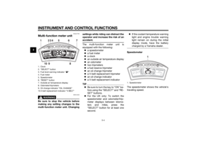
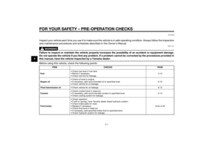
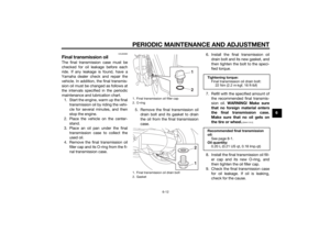
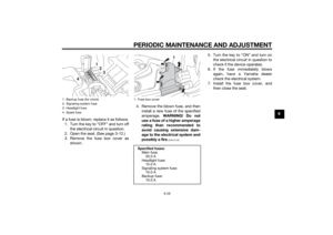
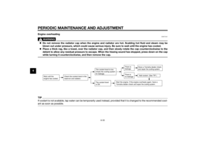
4. Remove the final transmission oil filler cap and its O-ring from the fi-
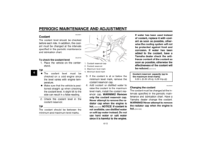
nal transmission case. 5. Remove the final transmission oil
drain bolt and its gasket to drain
the oil from the final transmission
case. 6. Install the final transmission oil
drain bolt and its new gasket, and
then tighten the bolt to the speci-
fied torque.
7. Refill with the specified amount of the recommended final transmis-
sion oil. WARNING! Make sure
that no forei gn material enters
the final transmission case.
Make sure that no oil gets on
the tire or wheel.
[EWA11312]
8. Install the final transmission oil fill- er cap and its new O-ring, and
then tighten the oil filler cap.
9. Check the final transmission case for oil leakage. If oil is leaking,
check for the cause.
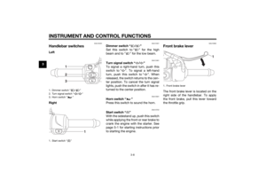
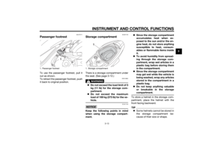
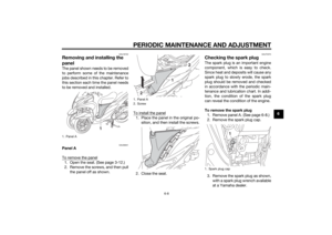
1. Final transmission oil filler cap
2. O-ring
1. Final transmission oil drain bolt
2. Gasket
1
212
Tightenin g torque:
Final transmission oil drain bolt: 22 Nm (2.2 m·kgf, 16 ft·lbf)
Recommen ded final transmission
oil: See page 8-1.
Oil quantity: 0.20 L (0.21 US qt, 0.18 Imp.qt)
U2CME0E0.book Page 12 Friday, May 2, 2014 2:55 PM
Page 52 of 84

PERIODIC MAINTENANCE AND ADJUSTMENT
6-13
6
EAU20071
CoolantThe coolant level should be checked
before each ride. In addition, the cool-
ant must be changed at the intervals
specified in the periodic maintenance
and lubrication chart.
EAU40155
To check the coolant level1. Place the vehicle on the center- stand.TIPThe coolant level must be
checked on a cold engine since
the level varies with engine tem-
perature.
Make sure that the vehicle is posi-
tioned straight up when checking
the coolant level. A slight tilt to the
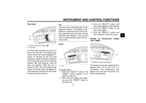
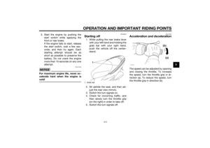
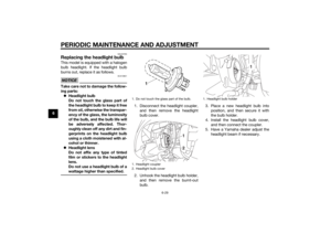
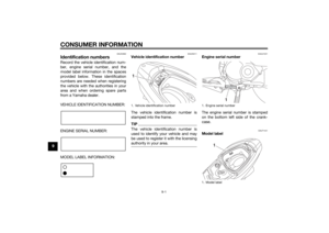
side can result in a false reading.2. Check the coolant level in the
coolant reservoir.TIPThe coolant should be between the
minimum and maximum level marks.
3. If the coolant is at or below theminimum level mark, remove the
coolant reservoir cap.
4. Add coolant or distilled water to raise the coolant to the maximum
level mark, install the coolant res-
ervoir cap. WARNING! Remove
only the coolant reservoir cap.
Never attempt to remove the ra-
d iator cap when the en gine is
hot.
[EWA15162]
NOTICE: If coolant is
not availab le, use distille d water
or soft tap water instea d. Do not
use har d water or salt water
since it is harmful to the en gine. If water has
been used instead
of coolant, replace it with cool-
ant as soon as possi ble, other-
wise the coolin g system will not
b e protecte d a gainst frost an d
corrosion. If water has been
a dde d to the coolant, have a
Yamaha dealer check the anti-
freeze content of the coolant as
soon as possi ble, otherwise the
effectiveness of the coolant will
b e re duce d.
[ECA10473]
EAU33032
Changin g the coolant
The coolant must be changed at the in-
tervals specified in the periodic main-
tenance and lubrication chart. Have a
Yamaha dealer change the coolant.
WARNING! Never attempt to remove the ra diator cap when the en gine is
hot.
[EWA10382]
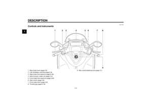
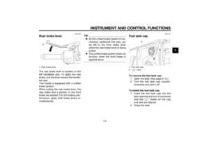
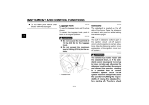
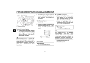
1. Coolant reservoir cap
2. Coolant reservoir
3. Maximum level mark
4. Minimum level mark
12
34
Coolant reservoir capacity (up to
the maximum level mark): 0.33 L (0.35 US qt, 0.29 Imp.qt)
U2CME0E0.book Page 13 Friday, May 2, 2014 2:55 PM
Page 53 of 84

PERIODIC MAINTENANCE AND ADJUSTMENT
6-14
6
EAU60991
Air filter and V- belt case air fil-
ter elementsThe air filter element should be re-
placed and the V-belt case air filter el-
ement should be cleaned at the
intervals specified in the periodic main-
tenance and lubrication chart. Service
the air filter elements more frequently if
you are riding in unusually wet or dusty
areas. The air filter check hose and V-
belt case air filter check hose must be
frequently checked and cleaned if nec-
essary.
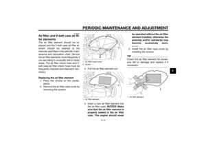
Replacin g the air filter element
1. Place the vehicle on the center- stand.
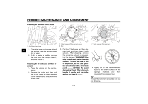
2. Remove the air filter case cover by removing the screws. 3. Pull the air filter element out.
4. Insert a new air filter element into
the air filter case. NOTICE: Make
sure that the air filter element is
properly seated in the air filter
case. The en gine shoul d never b
e operated without the air filter
element installed , otherwise the
piston(s) an d/or cylin der(s) may
b ecome excessively worn.
[ECA10482]
5. Install the air filter case cover by
installing the screws.TIPCheck the air filter element for exces-
sive dirt or damage and replace it if
necessary.
1. Air filter case cover
2. Screw
1. Air filter element
1
21
1. Air filter element
1
U2CME0E0.book Page 14 Friday, May 2, 2014 2:55 PM
Page 54 of 84

PERIODIC MAINTENANCE AND ADJUSTMENT
6-15
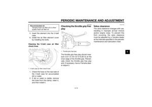
6Cleanin
g the air filter check hose
1. Check the hose on the rear side of the air filter case for accumulated
dirt or water.
2. If dirt or water is visible, remove the hose from the clamp, clean it,
and then install it.
Cleanin g the V- belt case air filter el-
ement 1. Place the vehicle on the center- stand.
2. Remove the bolts, and then pull the V-belt case air filter element
cover outward and away from the
V-belt case. 3. Pull the V-belt case air filter ele-
ment out, and then clean it with
solvent. After cleaning, remove
the remaining solvent by squeez-
ing the element. WARNING! Use
only a ded icated parts cleanin g
solvent. To avoi d the risk of fire
or explosion, do not use gaso-
line or solvents with a low flash
point.
[EWA10432]
NOTICE: To avoi d
d amag ing the air filter element,
han dle it gently an d carefully,
an d d o not twist it.
[ECA10522]
4. Apply oil of the recommended
type to the entire surface of the
sponge material, and then
squeeze the excess oil out.TIPThe air filter element should be wet but
not dripping.
1. Air filter check hose
1
1. V-belt case air filter element cover
2. Bolt
1
2
2
1. V-belt case air filter element
1
U2CME0E0.book Page 15 Friday, May 2, 2014 2:55 PM
Page 55 of 84

PERIODIC MAINTENANCE AND ADJUSTMENT
6-16
6
5. Insert the element into the V-belt
case.
6. Install the air filter element cover by installing the bolts.
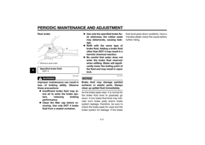
Cleanin g the V- belt case air filter
check hose
1. Check the hose on the rear side of the V-belt case for accumulated
dirt or water.
2. If dirt or water is visible, remove the hose from the clamp, clean it,
and then install it.
EAU21385
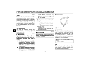
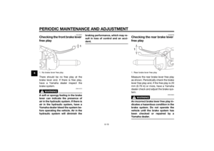
Checkin g the throttle grip free
playThe throttle grip free play should mea-
sure 3.0–7.0 mm (0.12–0.28 in) at the
inner edge of the throttle grip. Periodi-
cally check the throttle grip free play
and, if necessary, have a Yamaha deal-
er adjust it.
EAU21402
Valve clearanceThe valve clearance changes with use,
resulting in improper air-fuel mixture
and/or engine noise. To prevent this
from occurring, the valve clearance
must be adjusted by a Yamaha dealer
at the intervals specified in the periodic
maintenance and lubrication chart.
Recommen ded oil:
Yamaha foam air filter oil or other
quality foam air filter oil1. V-belt case air filter check hose
1
1. Throttle grip free play
1
U2CME0E0.book Page 16 Friday, May 2, 2014 2:55 PM
Page 56 of 84

PERIODIC MAINTENANCE AND ADJUSTMENT
6-17
6
EAU62200
TiresTires are the only contact between the
vehicle and the road. Safety in all con-
ditions of riding depends on a relatively
small area of road contact. Therefore, it
is essential to maintain the tires in good
condition at all times and replace them
at the appropriate time with the speci-
fied tires.
Tire air pressure
The tire air pressure should be
checked and, if necessary, adjusted
before each ride.
WARNING
EWA10504
Operation of this vehicle with im-
proper tire pressure may cause se-
vere injury or death from loss of
control. The tire air pressure must be
checked and a djuste d on col d
tires (i.e., when the temperature
of the tires equals the am bient
temperature).
The tire air pressure must be
a d juste d in accor dance with the
ri din g speed and with the total wei
ght of ri der, passen ger, car-
g o, an d accessories approve d
for this mo del.
WARNING
EWA10512
Never overloa d your vehicle. Opera-
tion of an overloa ded vehicle coul d
cause an acci dent.
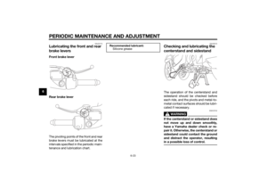
Tire inspection
The tires must be checked before each
ride. If the center tread depth reaches
the specified limit, if the tire has a nail
or glass fragments in it, or if the side-
wall is cracked, have a Yamaha dealer
replace the tire immediately.TIPThe tire tread depth limit may differ
from country to country. Always com-
ply with the local regulations.
Tire air pressure (measure d on col d
tires): Front:175 kPa (1.75 kgf/cm2, 25 psi)
Rear: 225 kPa (2.25 kgf/cm2, 33 psi)
Maximum loa d*:
169 kg (373 lb)
* Total weight of rider, passenger, car- go and accessories
1. Tire sidewall
2. Tire tread depthMinimum tire trea d d epth (front an d
rear): 1.6 mm (0.06 in)
U2CME0E0.book Page 17 Friday, May 2, 2014 2:55 PM