2014 YAMAHA TRICITY oil level
[x] Cancel search: oil levelPage 6 of 84

TABLE OF CONTENTSSAFETY INFORMATION.................. 1-1
Further safe-riding points ............... 1-5
DESCRIPTION .................................. 2-1
Left view ......................................... 2-1
Right view ....................................... 2-2
Controls and instruments ............... 2-3
INSTRUMENT AND CONTROL
FUNCTIONS ...................................... 3-1
Main switch/steering lock............... 3-1
Keyhole shutter .............................. 3-2
Indicator lights and warning lights............................................ 3-2
Self-diagnosis device ..................... 3-3
Multi-function meter unit ................ 3-4
Handlebar switches ........................ 3-8
Front brake lever ............................ 3-8
Rear brake lever ............................. 3-9
Fuel tank cap .................................. 3-9
Fuel ............................................... 3-10
Catalytic converter ....................... 3-11
Seat .............................................. 3-12
Passenger footrest ....................... 3-13
Storage compartment .................. 3-13
Luggage hook............................... 3-14
Sidestand ..................................... 3-14
Ignition circuit cut-off system ....... 3-15
Auxiliary DC connector ................. 3-17 FOR YOUR SAFETY –
PRE-OPERATION CHECKS
............. 4-1
OPERATION AND IMPORTANT
RIDING POINTS ................................ 5-1
Starting the engine .......................... 5-1
Starting off ...................................... 5-2
Acceleration and deceleration ........ 5-2
Braking ............................................ 5-3
Tips for reducing fuel consumption ................................ 5-3
Engine break-in ............................... 5-3
Parking ............................................ 5-4
PERIODIC MAINTENANCE AND
ADJUSTMENT ................................... 6-1
Owner’s tool kit ............................... 6-2
Periodic maintenance chart for the
emission control system .............. 6-3
General maintenance and
lubrication chart ........................... 6-4
Removing and installing the panel ............................................ 6-8
Checking the spark plug ................. 6-8
Engine oil and oil strainer .............. 6-10
Final transmission oil..................... 6-12
Coolant.......................................... 6-13
Air filter and V-belt case air filter elements .................................... 6-14
Checking the throttle grip free play ............................................ 6-16 Valve clearance............................. 6-16
Tires .............................................. 6-17
Cast wheels .................................. 6-18
Checking the front brake lever
free play..................................... 6-19
Checking the rear brake lever free play..................................... 6-19
Checking the front and rear
brake pads ................................ 6-20
Checking the brake fluid level ...... 6-20
Changing the brake fluid .............. 6-22
Checking and lubricating the cables ........................................ 6-22
Checking and lubricating the
throttle grip and cable ............... 6-22
Lubricating the front and rear brake levers ............................... 6-23
Checking and lubricating the centerstand and sidestand........ 6-23
Checking the front fork ................. 6-24
Checking the steering................... 6-25
Checking the wheel bearings ....... 6-25
Checking the steering tie rod ....... 6-25
Checking the leaning system ....... 6-26
Battery .......................................... 6-26
Replacing the fuses ...................... 6-27
Replacing the headlight bulb ........ 6-29
Tail/brake light .............................. 6-30
Turn signal light bulb .................... 6-30
Auxiliary light ................................ 6-30
Troubleshooting............................ 6-31U2CME0E0.book Page 1 Friday, May 2, 2014 2:55 PM
Page 20 of 84

INSTRUMENT AND CONTROL FUNCTIONS
3-4
3
EAUU1730
Multi-function meter unit
WARNING
EWA12423
Be sure to stop the vehicle before
makin g any settin g chan ges to the
multi-function meter unit. Chan gin g settin
gs while ri din g can d istract the
operator an d increase the risk of an
acci dent.
The multi-function meter unit is
equipped with the following:
a speedometer
a fuel meter
a clock
an outside air temperature display
an odometer
two tripmeters
a fuel reserve tripmeter
an oil change tripmeter
a V-belt replacement tripmeter
an oil change indicator
a V-belt replacement indicatorTIPBe sure to turn the key to “ON” be-
fore using the “SELECT” and “RE-
SET” buttons.
For the UK only: To switch the
speedometer and odometer/trip-
meter displays between kilome-
ters and miles, press the
“SELECT” button for at least one
second.
If the coolant temperature warning
light and engine trouble warning
light remain on during the initial
display mode, have the battery
charged by a Yamaha dealer.
Speed ometer
The speedometer shows the vehicle’s
traveling speed.
1. Clock
2. “SELECT” button
3. Fuel level warning indicator “ ”
4. Fuel meter
5. Speedometer
6. “RESET” button
7. Outside air temperature display
8. Odometer/tripmeters
9. Oil change indicator “OIL CHANGE”
10.V-belt replacement indicator “V-BELT”1
234
7
5
68
9
10
1. Speedometer
1
U2CME0E0.book Page 4 Friday, May 2, 2014 2:55 PM
Page 22 of 84

INSTRUMENT AND CONTROL FUNCTIONS
3-6
3
TIPIf the outside air temperature falls
below –10 °C, a lower temperature
than –10 °C will not be displayed.
If the outside air temperature
climbs above 40 °C, a higher tem-
perature than 40 °C will not be dis-
played.
The accuracy of the temperature
reading may be affected when rid-
ing slowly [approximately under
20 km/h (12 mi/h)] or when
stopped at traffic signals, railroad
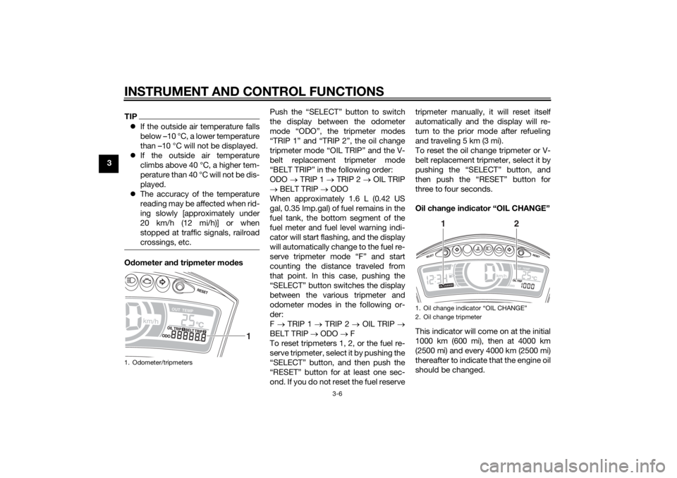
crossings, etc.Odometer an d tripmeter mo des Push the “SELECT” button to switch
the display between the odometer
mode “ODO”, the tripmeter modes
“TRIP 1” and “TRIP 2”, the oil change
tripmeter mode “OIL TRIP” and the V-
belt replacement tripmeter mode
“BELT TRIP” in the following order:
ODO
TRIP 1 TRIP 2 OIL TRIP
BELT TRIP ODO
When approximately 1.6 L (0.42 US
gal, 0.35 Imp.gal) of fuel remains in the
fuel tank, the bottom segment of the
fuel meter and fuel level warning indi-
cator will start flashing, and the display
will automatically change to the fuel re-
serve tripmeter mode “F” and start
counting the distance traveled from
that point. In this case, pushing the
“SELECT” button switches the display
between the various tripmeter and
odometer modes in the following or-
der:
F TRIP 1 TRIP 2 OIL TRIP
BELT TRIP ODO F
To reset tripmeters 1, 2, or the fuel re-
serve tripmeter, select it by pushing the
“SELECT” button, and then push the
“RESET” button for at least one sec-
ond. If you do not reset the fuel reserve tripmeter manually, it will reset itself
automatically and the display will re-
turn to the prior mode after refueling
and traveling 5 km (3 mi).
To reset the oil change tripmeter or V-
belt replacement tripmeter, select it by
pushing the “SELECT” button, and
then push the “RESET” button for
three to four seconds.
Oil chan
ge in dicator “OIL CHANGE”
This indicator will come on at the initial
1000 km (600 mi), then at 4000 km
(2500 mi) and every 4000 km (2500 mi)
thereafter to indicate that the engine oil
should be changed.1. Odometer/tripmeters
1
1. Oil change indicator “OIL CHANGE”
2. Oil change tripmeter
1
2
U2CME0E0.book Page 6 Friday, May 2, 2014 2:55 PM
Page 34 of 84

FOR YOUR SAFETY – PRE-OPERATION CHECKS
4-1
4
EAU15598
Inspect your vehicle each time you use it to make sure the vehicle is in safe operating condition. Always follow the inspection
and maintenance procedures and schedules described in the Owner’s Manual.
WARNING
EWA11152
Failure to inspect or maintain the vehicle properly increases the possibility of an acci dent or equipment damag e.
Do not operate the vehicle if you fin d any pro blem. If a pro blem cannot be corrected b y the proce dures provi ded in
this manual, have the vehicle inspecte d b y a Yamaha dealer.Before using this vehicle, check the following points:
ITEM CHECKS PAGE
Fuel • Check fuel level in fuel tank.
• Refuel if necessary.
• Check fuel line for leakage. 3-10
En gine oil • Check oil level in engine.
• If necessary, add recommended oil to specified level.
• Check vehicle for oil leakage. 6-10
Final transmission oil • Check vehicle for oil leakage. 6-12
Coolant • Check coolant level in reservoir.
• If necessary, add recommended coolant to specified level.
• Check cooling system for leakage. 6-13
Front brake • Check operation.
• If soft or spongy, have Yamaha dealer bleed hydraulic system.
• Check brake pads for wear.
• Replace if necessary.
• Check fluid level in reservoir.
• If necessary, add specified brake fluid to specified level.
• Check hydraulic system for leakage. 6-20, 6-20
U2CME0E0.book Page 1 Friday, May 2, 2014 2:55 PM
Page 45 of 84

PERIODIC MAINTENANCE AND ADJUSTMENT
6-6
6
20*Shock a
bsor ber as-
sem blies • Check operation and shock ab-
sorbers for oil leakage.
21 En gine oil • Change.
• Check oil level and vehicle for oil
leakage.
22 En gine oil strainer • Clean.
23 *Coolin g system • Check coolant level and vehicle
for coolant leakage.
• Change coolant. Every 3 years
24 Final transmission
oil • Check vehicle for oil leakage.
• Change. Every 12000 km (7200 mi)
25 *V-belt • Replace. Every 20000 km (12000 mi)
26 *Front an
d rear
b rake switches • Check operation.
27 Movin
g parts an d
ca bles • Lubricate.
28 *Throttle g rip • Check operation.
• Check throttle grip free play, and
adjust if necessary.
• Lubricate cable and grip housing.
29 *Li
ghts, si gnals an d
switches • Check operation.
• Adjust headlight beam.
NO. ITEM CHECK OR MAINTENANCE JOB
ODOMETER READING
ANNUAL
CHECK
1000 km
(600 mi) 4000 km
(2400 mi) 8000 km
(4800 mi) 12000 km
(7200 mi) 1600
0 km
(9600 mi)
U2CME0E0.book Page 6 Friday, May 2, 2014 2:55 PM
Page 46 of 84

PERIODIC MAINTENANCE AND ADJUSTMENT
6-7
6
EAU38263
TIPEngine air filter and V-belt air filters
• This model’s engine air filter is equipped with a disposable oil-coated paper element, which must not be cleaned with compressed air to avoid damaging it.
• The engine air filter element needs to be replaced and the V-belt air filter elements need to be serviced more fre- quently when riding in unusually wet or dusty areas.
Hydraulic brake service
• After disassembling the brake master cylinders and calipers, always change the fluid. Regularly check the brake fluid levels and fill the reservoirs as required.
• Every two years replace the internal components of the brake master cylinders and calipers, and change the brake fluid.
• Replace the brake hoses every four years and if cracked or damaged.
U2CME0E0.book Page 7 Friday, May 2, 2014 2:55 PM
Page 49 of 84

PERIODIC MAINTENANCE AND ADJUSTMENT
6-10
6
EAU61000
Engine oil an d oil strainerThe engine oil level should be checked
before each ride. In addition, the oil
must be changed and the oil strainer
cleaned at the intervals specified in the
periodic maintenance and lubrication
chart.
To check the en gine oil level
1. Place the vehicle on the center- stand. A slight tilt to the side can
result in a false reading.
2. Start the engine, warm it up for several minutes, and then turn it
off.
3. Wait a few minutes until the oil set- tles, remove the engine oil filler
cap, wipe the engine oil dipstick
clean, insert it back into the oil fill-
er hole (without screwing it in), and
then remove it again to check the
oil level. WARNING! The muffler
an d muffler protector become
very hot d uring use. To avoi d
possi ble burns, let the muffler
an d protector cool b efore re-
movin g the oil filler cap.
[EWA17810]
TIPThe engine oil should be between the
tip of the dipstick and the maximum
level mark.4. If the engine oil is not between the
tip of the dipstick and the maxi-
mum level mark, add sufficient oil
of the recommended type to raise
it to the correct level.
5. Insert the dipstick into the oil filler hole, and then tighten the oil filler
cap. To chan
ge the en gine oil an d clean
the oil strainer 1. Start the engine, warm it up for several minutes, and then turn it
off.
2. Place an oil pan under the engine to collect the used oil.
3. Remove the engine oil filler cap and engine oil drain bolts A and B
to drain the oil from the crankcase.
NOTICE: When removin g the
en gine oil drain bolt B, the O-
rin g, compression spring , and
oil strainer will fall out. Take
care not to lose these parts.
[ECAT1022]
1. Engine oil filler cap
2. Engine oil dipstick
3. Maximum level mark
4. Tip of the engine oil dipstick
1
234
U2CME0E0.book Page 10 Friday, May 2, 2014 2:55 PM
Page 50 of 84

PERIODIC MAINTENANCE AND ADJUSTMENT
6-11
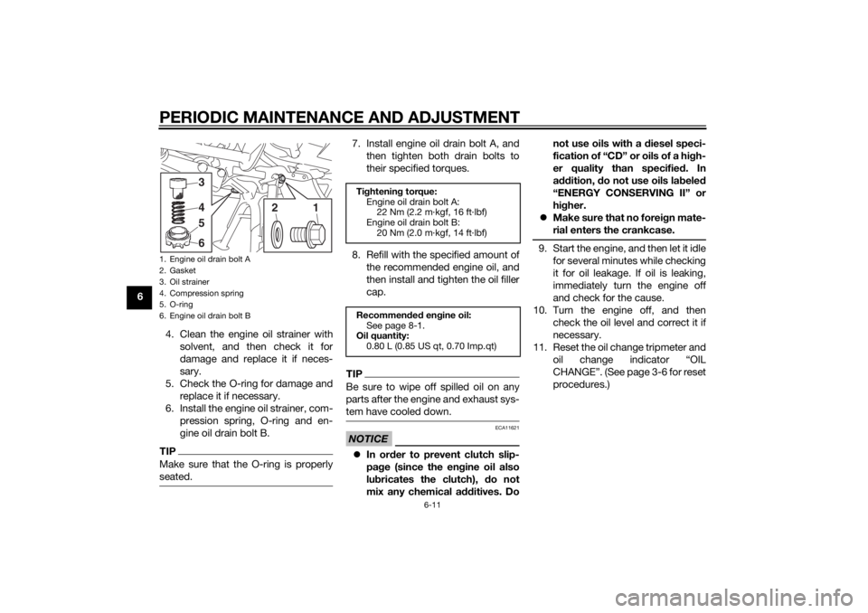
64. Clean the engine oil strainer withsolvent, and then check it for
damage and replace it if neces-
sary.
5. Check the O-ring for damage and replace it if necessary.
6. Install the engine oil strainer, com- pression spring, O-ring and en-
gine oil drain bolt B.
TIPMake sure that the O-ring is properly
seated.
7. Install engine oil drain bolt A, andthen tighten both drain bolts to
their specified torques.
8. Refill with the specified amount of the recommended engine oil, and
then install and tighten the oil filler
cap.TIPBe sure to wipe off spilled oil on any
parts after the engine and exhaust sys-
tem have cooled down.NOTICE
ECA11621
In or der to prevent clutch slip-
pa ge (since the en gine oil also
lu bricates the clutch), do not
mix any chemical additives. Do not use oils with a
diesel speci-
fication of “CD” or oils of a hi gh-
er quality than specifie d. In
a ddition, do not use oils la beled
“ENERGY CONSERVING II” or
hi gher.
Make sure that no forei gn mate-
rial enters the crankcase.
9. Start the engine, and then let it idle for several minutes while checking
it for oil leakage. If oil is leaking,
immediately turn the engine off
and check for the cause.
10. Turn the engine off, and then check the oil level and correct it if
necessary.
11. Reset the oil change tripmeter and oil change indicator “OIL
CHANGE”. (See page 3-6 for reset
procedures.)
1. Engine oil drain bolt A
2. Gasket
3. Oil strainer
4. Compression spring
5. O-ring
6. Engine oil drain bolt B
1
3456
2
Tightenin g torque:
Engine oil drain bolt A: 22 Nm (2.2 m·kgf, 16 ft·lbf)
Engine oil drain bolt B:
20 Nm (2.0 m·kgf, 14 ft·lbf)
Recommen ded en gine oil:
See page 8-1.
Oil quantity: 0.80 L (0.85 US qt, 0.70 Imp.qt)
U2CME0E0.book Page 11 Friday, May 2, 2014 2:55 PM