2014 YAMAHA TRICITY fuel cap
[x] Cancel search: fuel capPage 6 of 84

TABLE OF CONTENTSSAFETY INFORMATION.................. 1-1
Further safe-riding points ............... 1-5
DESCRIPTION .................................. 2-1
Left view ......................................... 2-1
Right view ....................................... 2-2
Controls and instruments ............... 2-3
INSTRUMENT AND CONTROL
FUNCTIONS ...................................... 3-1
Main switch/steering lock............... 3-1
Keyhole shutter .............................. 3-2
Indicator lights and warning lights............................................ 3-2
Self-diagnosis device ..................... 3-3
Multi-function meter unit ................ 3-4
Handlebar switches ........................ 3-8
Front brake lever ............................ 3-8
Rear brake lever ............................. 3-9
Fuel tank cap .................................. 3-9
Fuel ............................................... 3-10
Catalytic converter ....................... 3-11
Seat .............................................. 3-12
Passenger footrest ....................... 3-13
Storage compartment .................. 3-13
Luggage hook............................... 3-14
Sidestand ..................................... 3-14
Ignition circuit cut-off system ....... 3-15
Auxiliary DC connector ................. 3-17 FOR YOUR SAFETY –
PRE-OPERATION CHECKS
............. 4-1
OPERATION AND IMPORTANT
RIDING POINTS ................................ 5-1
Starting the engine .......................... 5-1
Starting off ...................................... 5-2
Acceleration and deceleration ........ 5-2
Braking ............................................ 5-3
Tips for reducing fuel consumption ................................ 5-3
Engine break-in ............................... 5-3
Parking ............................................ 5-4
PERIODIC MAINTENANCE AND
ADJUSTMENT ................................... 6-1
Owner’s tool kit ............................... 6-2
Periodic maintenance chart for the
emission control system .............. 6-3
General maintenance and
lubrication chart ........................... 6-4
Removing and installing the panel ............................................ 6-8
Checking the spark plug ................. 6-8
Engine oil and oil strainer .............. 6-10
Final transmission oil..................... 6-12
Coolant.......................................... 6-13
Air filter and V-belt case air filter elements .................................... 6-14
Checking the throttle grip free play ............................................ 6-16 Valve clearance............................. 6-16
Tires .............................................. 6-17
Cast wheels .................................. 6-18
Checking the front brake lever
free play..................................... 6-19
Checking the rear brake lever free play..................................... 6-19
Checking the front and rear
brake pads ................................ 6-20
Checking the brake fluid level ...... 6-20
Changing the brake fluid .............. 6-22
Checking and lubricating the cables ........................................ 6-22
Checking and lubricating the
throttle grip and cable ............... 6-22
Lubricating the front and rear brake levers ............................... 6-23
Checking and lubricating the centerstand and sidestand........ 6-23
Checking the front fork ................. 6-24
Checking the steering................... 6-25
Checking the wheel bearings ....... 6-25
Checking the steering tie rod ....... 6-25
Checking the leaning system ....... 6-26
Battery .......................................... 6-26
Replacing the fuses ...................... 6-27
Replacing the headlight bulb ........ 6-29
Tail/brake light .............................. 6-30
Turn signal light bulb .................... 6-30
Auxiliary light ................................ 6-30
Troubleshooting............................ 6-31U2CME0E0.book Page 1 Friday, May 2, 2014 2:55 PM
Page 15 of 84

DESCRIPTION
2-2
2
EAU10421
Right view
1
3
4,5
6
2
8
7
1. Owner’s tool kit (page 6-2)
2. Passenger footrest (page 3-13)
3. Fuel tank cap (page 3-9)
4. Main fuse (page 6-27)
5. Fuse box (page 6-27)
6. Battery (page 6-26)
7. Spark plug (page 6-8)
8. Engine oil filler cap (page 6-10)
U2CME0E0.book Page 2 Friday, May 2, 2014 2:55 PM
Page 25 of 84

INSTRUMENT AND CONTROL FUNCTIONS
3-9
3
EAUS1963
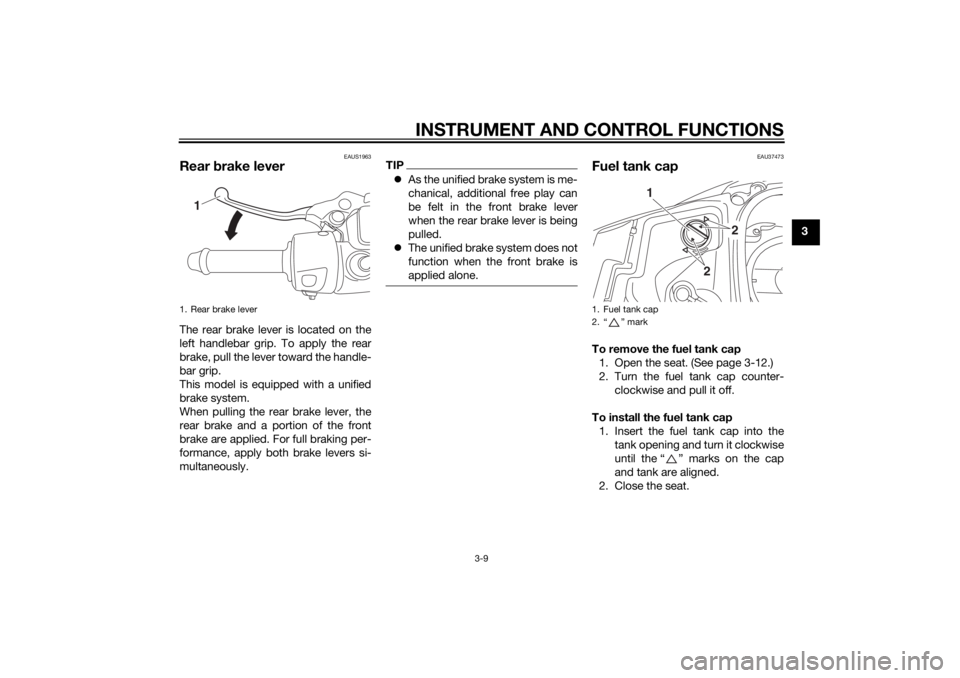
Rear brake leverThe rear brake lever is located on the
left handlebar grip. To apply the rear
brake, pull the lever toward the handle-
bar grip.
This model is equipped with a unified
brake system.
When pulling the rear brake lever, the
rear brake and a portion of the front
brake are applied. For full braking per-
formance, apply both brake levers si-
multaneously.
TIP As the unified brake system is me-
chanical, additional free play can
be felt in the front brake lever
when the rear brake lever is being
pulled.
The unified brake system does not
function when the front brake is
applied alone.
EAU37473
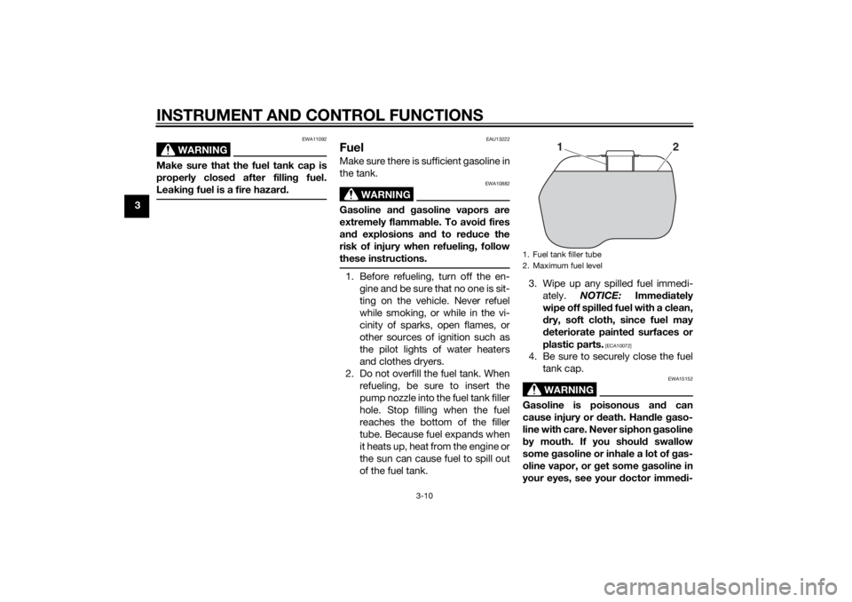
Fuel tank capTo remove the fuel tank cap
1. Open the seat. (See page 3-12.)
2. Turn the fuel tank cap counter- clockwise and pull it off.
To install the fuel tank cap 1. Insert the fuel tank cap into the tank opening and turn it clockwise
until the “ ” marks on the cap
and tank are aligned.
2. Close the seat.
1. Rear brake lever
1
1. Fuel tank cap
2. “ ” mark
2
2
1
U2CME0E0.book Page 9 Friday, May 2, 2014 2:55 PM
Page 26 of 84

INSTRUMENT AND CONTROL FUNCTIONS
3-10
3
WARNING
EWA11092
Make sure that the fuel tank cap is
properly closed after fillin g fuel.
Leakin g fuel is a fire hazar d.
EAU13222
FuelMake sure there is sufficient gasoline in
the tank.
WARNING
EWA10882
Gasoline an d g asoline vapors are
extremely flamma ble. To avoi d fires
an d explosions an d to re duce the
risk of injury when refuelin g, follow
these instructions.1. Before refueling, turn off the en- gine and be sure that no one is sit-
ting on the vehicle. Never refuel
while smoking, or while in the vi-
cinity of sparks, open flames, or
other sources of ignition such as
the pilot lights of water heaters
and clothes dryers.
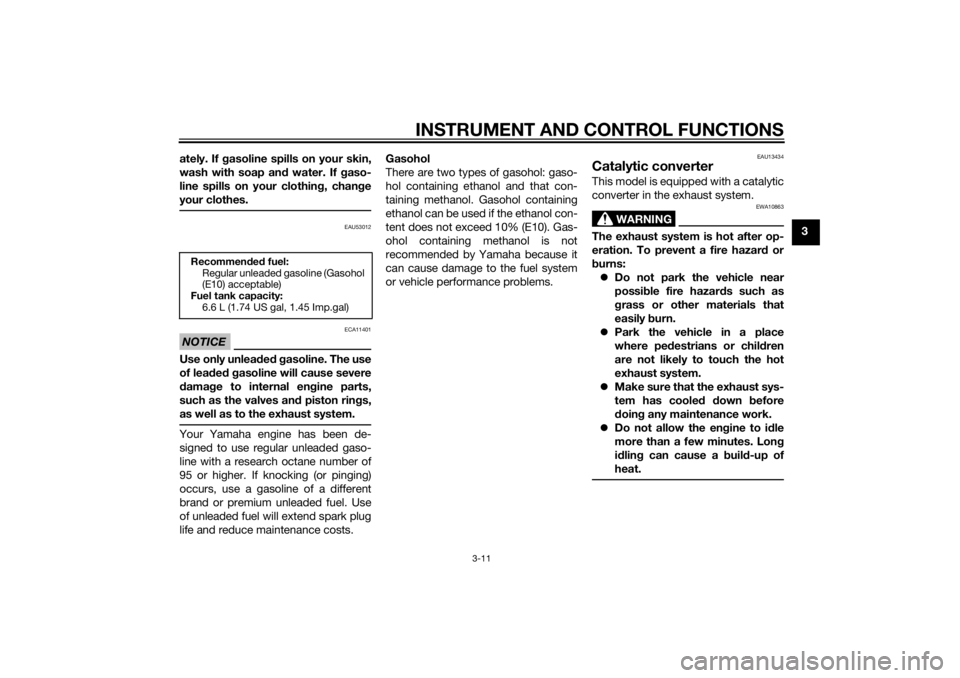
2. Do not overfill the fuel tank. When refueling, be sure to insert the
pump nozzle into the fuel tank filler
hole. Stop filling when the fuel
reaches the bottom of the filler
tube. Because fuel expands when
it heats up, heat from the engine or
the sun can cause fuel to spill out
of the fuel tank. 3. Wipe up any spilled fuel immedi-
ately. NOTICE: Immediately
wipe off spille d fuel with a clean,
d ry, soft cloth, since fuel may
d eteriorate painted surfaces or
plastic parts.
[ECA10072]
4. Be sure to securely close the fuel tank cap.
WARNING
EWA15152
Gasoline is poisonous an d can
cause injury or death. Han dle gaso-
line with care. Never siphon gasoline
b y mouth. If you shoul d swallow
some gasoline or inhale a lot of g as-
oline vapor, or g et some gasoline in
your eyes, see your doctor imme di-1. Fuel tank filler tube
2. Maximum fuel level
1
2
U2CME0E0.book Page 10 Friday, May 2, 2014 2:55 PM
Page 27 of 84

INSTRUMENT AND CONTROL FUNCTIONS
3-11
3
ately. If g
asoline spills on your skin,
wash with soap an d water. If gaso-
line spills on your clothin g, chan ge
your clothes.
EAU53012
NOTICE
ECA11401
Use only unlea ded g asoline. The use
of lead ed g asoline will cause severe
d amag e to internal en gine parts,
such as the valves an d piston rin gs,
as well as to the exhaust system.Your Yamaha engine has been de-
signed to use regular unleaded gaso-
line with a research octane number of
95 or higher. If knocking (or pinging)
occurs, use a gasoline of a different
brand or premium unleaded fuel. Use
of unleaded fuel will extend spark plug
life and reduce maintenance costs. Gasohol
There are two types of gasohol: gaso-
hol containing ethanol and that con-
taining methanol. Gasohol containing
ethanol can be used if the ethanol con-
tent does not exceed 10% (E10). Gas-
ohol containing methanol is not
recommended by Yamaha because it
can cause damage to the fuel system
or vehicle performance problems.
EAU13434
Catalytic converterThis model is equipped with a catalytic
converter in the exhaust system.
WARNING
EWA10863
The exhaust system is hot after op-
eration. To prevent a fire hazar
d or
b urns:
Do not park the vehicle near
possi ble fire hazar ds such as
g rass or other materials that
easily burn.
Park the vehicle in a place
where pe destrians or chil dren
are not likely to touch the hot
exhaust system.
Make sure that the exhaust sys-
tem has coole d down before
d oin g any maintenance work.
Do not allow the en gine to i dle
more than a few minutes. Lon g
i d lin g can cause a b uild-up of
heat.
Recommen ded fuel:
Regular unleaded gasoline (Gasohol
(E10) acceptable)
Fuel tank capacity:
6.6 L (1.74 US gal, 1.45 Imp.gal)
U2CME0E0.book Page 11 Friday, May 2, 2014 2:55 PM
Page 76 of 84

VEHICLE CARE AND STORAGE
7-4
7
EAU60721
StorageShort-term
Always store your vehicle in a cool, dry
place and, if necessary, protect it
against dust with a porous cover. Be
sure the engine and the exhaust sys-
tem are cool before covering the vehi-
cle.NOTICE
ECA21170
Storin g the vehicle in a poorly
ventilate d room or coverin g it
with a tarp, while it is still wet,
will allow water an d humi dity to
seep in an d cause rust.
To prevent corrosion, avoi d
d amp cellars, sta bles ( because
of the presence of ammonia)
an d areas where stron g chemi-
cals are stored .Long-term
Before storing your vehicle for several
months: 1. Follow all the instructions in the “Care” section of this chapter. 2. Fill up the fuel tank and add fuel
stabilizer (if available) to prevent
the fuel tank from rusting and the
fuel from deteriorating.
3. Perform the following steps to protect the cylinder, piston rings,
etc. from corrosion.a. Remove the spark plug cap and spark plug.
b. Pour a teaspoonful of engine oil into the spark plug bore.
c. Install the spark plug cap onto the spark plug, and then place
the spark plug on the cylinder
head so that the electrodes are
grounded. (This will limit spark-
ing during the next step.)
d. Turn the engine over several times with the starter. (This will
coat the cylinder wall with oil.)
e. Remove the spark plug cap from the spark plug, and then
install the spark plug and the
spark plug cap. WARNING! To
prevent dama ge or injury
from sparkin g, make sure to
g roun d the spark plu g elec-
tro des while turnin g the en-
g ine over.
[EWA10952]
4. Lubricate all control cables and
the pivoting points of all levers and
pedals as well as of the side-
stand/centerstand.
5. Check and, if necessary, correct the tire air pressure, and then lift
the vehicle so that both of its
wheels are off the ground. Alterna-
tively, turn the wheels a little every
month in order to prevent the tires
from becoming degraded in one
spot.
6. Cover the muffler outlet with a plastic bag to prevent moisture
from entering it.
7. Remove the battery and fully charge it. Store it in a cool, dry
place and charge it once a month.
Do not store the battery in an ex-
cessively cold or warm place [less
than 0 °C (30 °F) or more than 30
°C (90 °F)]. For more information
on storing the battery, see page
6-26.TIPMake any necessary repairs before
storing the vehicle.
U2CME0E0.book Page 4 Friday, May 2, 2014 2:55 PM
Page 77 of 84

SPECIFICATIONS
8-1
8
Dimensions:Overall length:1905 mm (75.0 in)
Overall width:
735 mm (28.9 in)
Overall height: 1215 mm (47.8 in)
Seat height: 780 mm (30.7 in)
Wheelbase:
1310 mm (51.6 in)
Ground clearance: 120 mm (4.72 in)
Minimum turning radius: 2300 mm (90.6 in)Wei ght:Curb weight:
152 kg (335 lb)Engine:Engine type:
Liquid cooled 4-stroke, SOHC
Cylinder arrangement: Single cylinder
Displacement: 124 cm3
Bore stroke:
52.4 57.9 mm (2.06 2.28 in)
Compression ratio: 10.9 : 1
Starting system: Electric starter
Lubrication system:
Wet sump
Engine oil:Recommended brand:
YAMALUBE
Type:
SAE 10W-40, 20W-40 or 20W-50
Recommended engine oil grade: API service SG type or higher, JASO
standard MA or MB
Engine oil quantity: Periodic oil change:
0.80 L (0.85 US qt, 0.70 Imp.qt)Final transmission oil:Type:YAMALUBE 10W-40 or SAE 10W-30 type SE motor oil
Quantity: 0.20 L (0.21 US qt, 0.18 Imp.qt)Coolin g system:Recommended antifreeze:
YAMAHA GENUINE COOLANT only
Coolant reservoir capacity (up to the
maximum level mark): 0.33 L (0.35 US qt, 0.29 Imp.qt) Radiator capacity (including all routes):
0.37 L (0.39 US qt, 0.33 Imp.qt)
Air filter:Air filter element:
Oil-coated paper elementFuel:Recommended fuel:Regular unleaded gasoline (Gasohol (E10)
acceptable)
Fuel tank capacity: 6.6 L (1.74 US gal, 1.45 Imp.gal)Fuel injection:Throttle body:ID mark:
2CM1 00Spark plu g(s):Manufacturer/model:
NGK/CR7E
Spark plug gap:
0.7–0.8 mm (0.028–0.031 in)Clutch:Clutch type:Dry, centrifugal automaticTransmission:Primary reduction ratio:1.000
Secondary reduction ratio: 9.533 (44/15 x 39/12)
Transmission type:
V-belt automaticChassis:Frame type:Underbone
–20 –10 0 1020 30 40 50 �C
10 30 50 70 90 110
0 130 �F
SAE 20W-50SAE 20W-40
SAE 10W-40
U2CME0E0.book Page 1 Friday, May 2, 2014 2:55 PM
Page 82 of 84

10-1
10
INDEXAAcceleration and deceleration ................ 5-2
Air filter and V-belt case air filter elements ............................................. 6-14
Auxiliary DC connector ......................... 3-17
Auxiliary light......................................... 6-30BBattery .................................................. 6-26
Brake fluid, changing ............................ 6-22
Brake fluid level, checking .................... 6-20
Brake lever, front .................................... 3-8
Brake lever, rear...................................... 3-9
Brake levers, lubricating ....................... 6-23
Braking.................................................... 5-3CCables, checking and lubricating ......... 6-22
Care ........................................................ 7-1
Catalytic converter ................................ 3-11
Centerstand and sidestand, checking and lubricating .................................... 6-23
Coolant ................................................. 6-13
Coolant temperature warning light ......... 3-3DDimmer switch ........................................ 3-8EEngine break-in....................................... 5-3
Engine oil and oil strainer...................... 6-10
Engine serial number .............................. 9-1
Engine trouble warning light ................... 3-3FFinal transmission oil ............................ 6-12
Front and rear brake pads, checking.... 6-20
Front brake lever free play, checking ... 6-19
Front fork, checking .............................. 6-24 Fuel ....................................................... 3-10
Fuel consumption, tips for reducing ...... 5-3
Fuel tank cap .......................................... 3-9
Fuses, replacing ................................... 6-27
HHandlebar switches ................................ 3-8
Headlight bulb, replacing ..................... 6-29
High beam indicator light ....................... 3-2
Horn switch ............................................ 3-8IIdentification numbers ............................ 9-1
Ignition circuit cut-off system ............... 3-15
Indicator lights and warning lights ......... 3-2KKeyhole shutter ...................................... 3-2LLeaning system, checking .................... 6-26
Luggage hook ...................................... 3-14MMain switch/steering lock....................... 3-1
Maintenance and lubrication, periodic ... 6-4
Maintenance, emission control
system.................................................. 6-3
Matte color, caution ............................... 7-1
Model label ............................................. 9-1
Multi-function meter unit ........................ 3-4PPanel, removing and installing ............... 6-8
Parking ................................................... 5-4
Part locations ......................................... 2-1
Passenger footrest ............................... 3-13RRear brake lever free play, checking .... 6-19
SSafe-riding points....................................1-5
Safety information ...................................1-1
Seat .......................................................3-12
Self-diagnosis device..............................3-3
Sidestand ..............................................3-14
Spark plug, checking ..............................6-8
Specifications .........................................8-1
Starting off ..............................................5-2
Starting the engine ..................................5-1
Start switch .............................................3-8
Steering, checking ................................6-25
Steering tie rod, checking .....................6-25
Storage ...................................................7-4
Storage compartment ...........................3-13TTail/brake light ......................................6-30
Throttle grip and cable, checking and
lubricating ...........................................6-22
Throttle grip free play, checking ...........6-16
Tires ......................................................6-17
Tool kit ....................................................6-2
Troubleshooting ....................................6-31
Troubleshooting charts .........................6-32
Turn signal indicator lights ......................3-2
Turn signal light bulb.............................6-30
Turn signal switch ...................................3-8VValve clearance .....................................6-16
Vehicle identification number ..................9-1WWheel bearings, checking .....................6-25
Wheels ..................................................6-18
U2CME0E0.book Page 1 Friday, May 2, 2014 2:55 PM