2014 YAMAHA TRICITY brake light
[x] Cancel search: brake lightPage 6 of 84

TABLE OF CONTENTSSAFETY INFORMATION.................. 1-1
Further safe-riding points ............... 1-5
DESCRIPTION .................................. 2-1
Left view ......................................... 2-1
Right view ....................................... 2-2
Controls and instruments ............... 2-3
INSTRUMENT AND CONTROL
FUNCTIONS ...................................... 3-1
Main switch/steering lock............... 3-1
Keyhole shutter .............................. 3-2
Indicator lights and warning lights............................................ 3-2
Self-diagnosis device ..................... 3-3
Multi-function meter unit ................ 3-4
Handlebar switches ........................ 3-8
Front brake lever ............................ 3-8
Rear brake lever ............................. 3-9
Fuel tank cap .................................. 3-9
Fuel ............................................... 3-10
Catalytic converter ....................... 3-11
Seat .............................................. 3-12
Passenger footrest ....................... 3-13
Storage compartment .................. 3-13
Luggage hook............................... 3-14
Sidestand ..................................... 3-14
Ignition circuit cut-off system ....... 3-15
Auxiliary DC connector ................. 3-17 FOR YOUR SAFETY –
PRE-OPERATION CHECKS
............. 4-1
OPERATION AND IMPORTANT
RIDING POINTS ................................ 5-1
Starting the engine .......................... 5-1
Starting off ...................................... 5-2
Acceleration and deceleration ........ 5-2
Braking ............................................ 5-3
Tips for reducing fuel consumption ................................ 5-3
Engine break-in ............................... 5-3
Parking ............................................ 5-4
PERIODIC MAINTENANCE AND
ADJUSTMENT ................................... 6-1
Owner’s tool kit ............................... 6-2
Periodic maintenance chart for the
emission control system .............. 6-3
General maintenance and
lubrication chart ........................... 6-4
Removing and installing the panel ............................................ 6-8
Checking the spark plug ................. 6-8
Engine oil and oil strainer .............. 6-10
Final transmission oil..................... 6-12
Coolant.......................................... 6-13
Air filter and V-belt case air filter elements .................................... 6-14
Checking the throttle grip free play ............................................ 6-16 Valve clearance............................. 6-16
Tires .............................................. 6-17
Cast wheels .................................. 6-18
Checking the front brake lever
free play..................................... 6-19
Checking the rear brake lever free play..................................... 6-19
Checking the front and rear
brake pads ................................ 6-20
Checking the brake fluid level ...... 6-20
Changing the brake fluid .............. 6-22
Checking and lubricating the cables ........................................ 6-22
Checking and lubricating the
throttle grip and cable ............... 6-22
Lubricating the front and rear brake levers ............................... 6-23
Checking and lubricating the centerstand and sidestand........ 6-23
Checking the front fork ................. 6-24
Checking the steering................... 6-25
Checking the wheel bearings ....... 6-25
Checking the steering tie rod ....... 6-25
Checking the leaning system ....... 6-26
Battery .......................................... 6-26
Replacing the fuses ...................... 6-27
Replacing the headlight bulb ........ 6-29
Tail/brake light .............................. 6-30
Turn signal light bulb .................... 6-30
Auxiliary light ................................ 6-30
Troubleshooting............................ 6-31U2CME0E0.book Page 1 Friday, May 2, 2014 2:55 PM
Page 24 of 84

INSTRUMENT AND CONTROL FUNCTIONS
3-8
3
EAU1234H
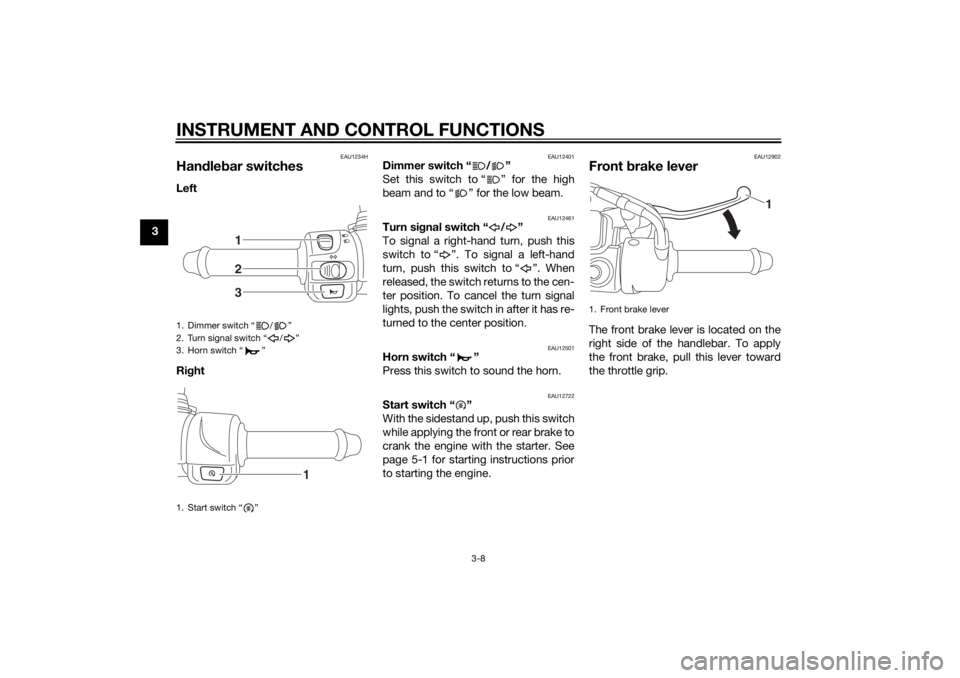
Handle bar switchesLeft
Ri ght
EAU12401
Dimmer switch “ / ”
Set this switch to “ ” for the high
beam and to “ ” for the low beam.
EAU12461
Turn si gnal switch “ / ”
To signal a right-hand turn, push this
switch to “ ”. To signal a left-hand
turn, push this switch to “ ”. When
released, the switch returns to the cen-
ter position. To cancel the turn signal
lights, push the switch in after it has re-
turned to the center position.
EAU12501
Horn switch “ ”
Press this switch to sound the horn.
EAU12722
Start switch “ ”
With the sidestand up, push this switch
while applying the front or rear brake to
crank the engine with the starter. See
page 5-1 for starting instructions prior
to starting the engine.
EAU12902
Front brake leverThe front brake lever is located on the
right side of the handlebar. To apply
the front brake, pull this lever toward
the throttle grip.
1. Dimmer switch “ / ”
2. Turn signal switch “ / ”
3. Horn switch “ ”
1. Start switch “ ”
123
1
1. Front brake lever
1
U2CME0E0.book Page 8 Friday, May 2, 2014 2:55 PM
Page 38 of 84

OPERATION AND IMPORTANT RIDING POINTS
5-3
5
EAU60650
Braking
WARNING
EWA17790
Avoi d b rakin g har d or su ddenly
(especially when leanin g over to
one si de), otherwise the vehicle
may skid or overturn.
Railroa d crossin gs, streetcar
rails, iron plates on roa d con-
struction sites, an d manhole
covers become extremely slip-
pery when wet. Therefore, slow
d own when approachin g such
areas an d cross them with cau-
tion.
Keep in min d that b raking on a
wet roa d is much more difficult.
Ride slowly d own a hill, as brak-
in g d ownhill can b e very diffi-
cult.1. Close the throttle completely.
2. Apply both front and rear brakes simultaneously while gradually in-
creasing the pressure.
EAU16821
Tips for re ducin g fuel con-
sumptionFuel consumption depends largely on
your riding style. Consider the follow-
ing tips to reduce fuel consumption:
Avoid high engine speeds during
acceleration.
Avoid high engine speeds with no
load on the engine.
Turn the engine off instead of let-
ting it idle for an extended length
of time (e.g., in traffic jams, at traf-
fic lights or at railroad crossings).
EAU16831
Engine break-inThere is never a more important period
in the life of your engine than the period
between 0 and 1000 km (600 mi). For
this reason, you should read the fol-
lowing material carefully.
Since the engine is brand new, do not
put an excessive load on it for the first
1000 km (600 mi). The various parts in
the engine wear and polish themselves
to the correct operating clearances.
During this period, prolonged full-throt-
tle operation or any condition that
might result in engine overheating
must be avoided.
EAU61040
0–150 km (0–90 mi)
Avoid prolonged operation above 1/3
throttle.
After every hour of operation, stop the
engine, and then let it cool for five to
ten minutes.
Vary the engine speed from time to
time. Do not operate the engine at one
set throttle position.
U2CME0E0.book Page 3 Friday, May 2, 2014 2:55 PM
Page 69 of 84

PERIODIC MAINTENANCE AND ADJUSTMENT
6-30
6
EAU24182
Tail/brake li ghtThis model is equipped with an LED-
type tail/brake light.
If the tail/brake light does not come on,
have a Yamaha dealer check it.
EAU61170
Turn si gnal li ght bul bIf a turn signal light does not come on,
have a Yamaha dealer check its electri-
cal circuit or replace the bulb.
EAU54501
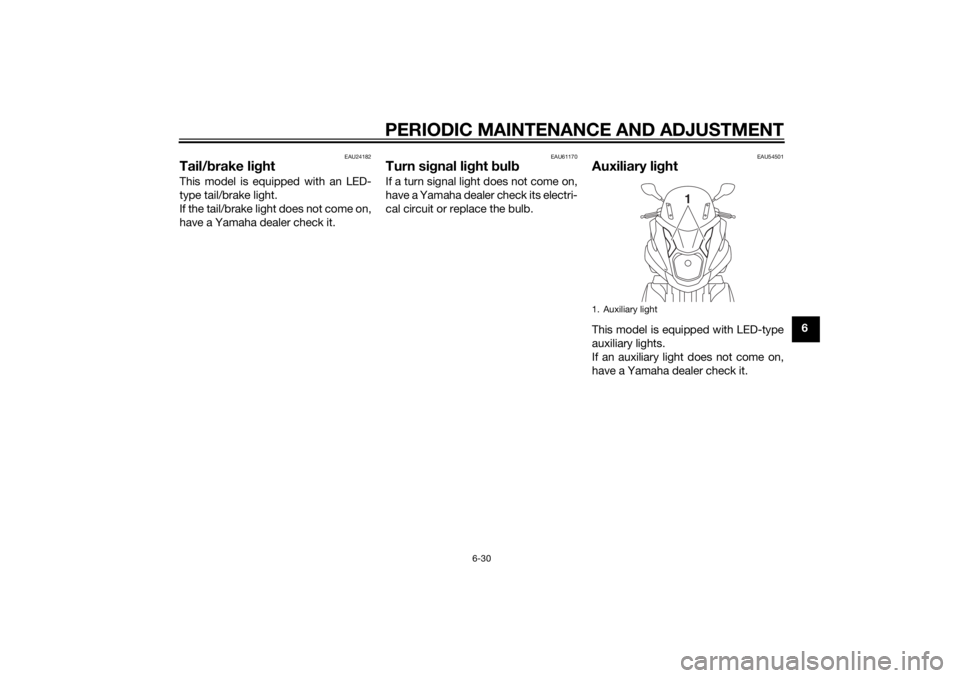
Auxiliary li ghtThis model is equipped with LED-type
auxiliary lights.
If an auxiliary light does not come on,
have a Yamaha dealer check it.1. Auxiliary light
1
U2CME0E0.book Page 30 Friday, May 2, 2014 2:55 PM
Page 75 of 84

VEHICLE CARE AND STORAGE
7-3
7
thoroughly with water. For additional
cleaning, use Yamaha Windshield
Cleaner or another high-quality wind-
shield cleaner. Some cleaning com-
pounds for plastics may leave
scratches on the windshield. Before
using such cleaners, test an area of the
windshield which does not affect your
visibility and which cannot be easily
recognized.
After cleanin
g
1. Dry the vehicle with a chamois or an absorbing cloth.
2. Use a chrome polish to shine chrome, aluminum, and stainless-
steel parts, including the exhaust
system. (Even the thermally in-
duced discoloring of stainless-
steel exhaust systems can be re-
moved through polishing.)
3. To prevent corrosion, it is recom- mended to apply a corrosion pro-
tection spray on all metal,
including chrome- and nickel-plat-
ed surfaces.
4. Use spray oil as a universal clean- er to remove any remaining dirt. 5. Touch up minor paint damage
caused by stones, etc.
6. Wax all painted surfaces.
7. Let the vehicle dry completely be- fore storing or covering it.
WARNING
EWA17830
Contaminants on the b rakes or tires
can cause loss of control. Make sure that there is no oil or
wax on the b rakes or tires. If
necessary, clean the brake
d iscs an d b rake linin gs with a
re gular brake disc cleaner or
acetone, an d wash the tires with
warm water an d a mil d d eter-
g ent.
Before operatin g the vehicle
test its brakin g performance
an d cornerin g b ehavior.NOTICE
ECAU0022
Apply spray oil an d wax spar-
in gly an d make sure to wipe off
any excess.
Never apply oil or wax to any
rubber parts, plastic parts or
hea dlig ht, tailli ght and meter
lenses, but treat them with a
suita ble care pro duct.
Avoi d using abrasive polishin g
compoun ds as they will wear
away the paint.
TIP Consult a Yamaha dealer for ad-
vice on what products to use.
Washing, rainy weather or humid
climates can cause the headlight
lens to fog. Turning the headlight
on for a short period of time will
help remove the moisture from the
lens.
U2CME0E0.book Page 3 Friday, May 2, 2014 2:55 PM
Page 78 of 84

SPECIFICATIONS
8-2
8
Caster angle:20.00 °
Trail: 68 mm (2.7 in)
Track:
385.0 mm (15.16 in)Front tire:Type:Tubeless
Size:
90/80-14M/C 43P
Manufacturer/model: CHENG SHIN/M6231Rear tire:Type:
Tubeless
Size: 110/90-12 64P
Manufacturer/model: CHENG SHIN/M6232Loa din g:Maximum load:
169 kg (373 lb)
(Total weight of rider, passenger, cargo
and accessories)Tire air pressure (measure d on col d
tires):
Front:
175 kPa (1.75 kgf/cm2, 25 psi)
Rear:
225 kPa (2.25 kgf/cm2, 33 psi)
Front wheel:Wheel type:Cast wheel Rim size:
14M/C x MT2.15
Rear wheel:Wheel type:
Cast wheel
Rim size: 12 x MT2.15Unifie d b rake system:Operation:
Activated by rear brakeFront brake:Type:
Disc brake
Operation:
Right hand operation
Specified brake fluid: YAMAHA GENUINE BRAKE FLUID (DOT 4)Rear brake:Type:
Disc brake
Operation: Left hand operation
Specified brake fluid: YAMAHA GENUINE BRAKE FLUID (DOT 4)Front suspension:Type:Telescopic fork
Spring/shock absorber type: Coil spring/oil damper
Wheel travel:
90 mm (3.5 in)Rear suspension:Type:Unit swing Spring/shock absorber type:
Coil spring/oil damper
Wheel travel: 89 mm (3.5 in)
Electrical system:Ignition system:TCI
Charging system: AC magnetoBattery:Model:YTZ7V
Voltage, capacity: 12 V, 6.0 AhHea dlig ht:Bulb type:
Halogen bulbBul b volta ge, watta ge quantity:Headlight:
12 V, 55.0 W/60.0 W 1
Tail/brake light: LED
Front turn signal light: 12 V, 10.0 W 2
Rear turn signal light:
12 V, 10.0 W 2
Meter lighting: LED
High beam indicator light: LED
Turn signal indicator light:
LED
Coolant temperature warning light: LED
U2CME0E0.book Page 2 Friday, May 2, 2014 2:55 PM
Page 82 of 84

10-1
10
INDEXAAcceleration and deceleration ................ 5-2
Air filter and V-belt case air filter elements ............................................. 6-14
Auxiliary DC connector ......................... 3-17
Auxiliary light......................................... 6-30BBattery .................................................. 6-26
Brake fluid, changing ............................ 6-22
Brake fluid level, checking .................... 6-20
Brake lever, front .................................... 3-8
Brake lever, rear...................................... 3-9
Brake levers, lubricating ....................... 6-23
Braking.................................................... 5-3CCables, checking and lubricating ......... 6-22
Care ........................................................ 7-1
Catalytic converter ................................ 3-11
Centerstand and sidestand, checking and lubricating .................................... 6-23
Coolant ................................................. 6-13
Coolant temperature warning light ......... 3-3DDimmer switch ........................................ 3-8EEngine break-in....................................... 5-3
Engine oil and oil strainer...................... 6-10
Engine serial number .............................. 9-1
Engine trouble warning light ................... 3-3FFinal transmission oil ............................ 6-12
Front and rear brake pads, checking.... 6-20
Front brake lever free play, checking ... 6-19
Front fork, checking .............................. 6-24 Fuel ....................................................... 3-10
Fuel consumption, tips for reducing ...... 5-3
Fuel tank cap .......................................... 3-9
Fuses, replacing ................................... 6-27
HHandlebar switches ................................ 3-8
Headlight bulb, replacing ..................... 6-29
High beam indicator light ....................... 3-2
Horn switch ............................................ 3-8IIdentification numbers ............................ 9-1
Ignition circuit cut-off system ............... 3-15
Indicator lights and warning lights ......... 3-2KKeyhole shutter ...................................... 3-2LLeaning system, checking .................... 6-26
Luggage hook ...................................... 3-14MMain switch/steering lock....................... 3-1
Maintenance and lubrication, periodic ... 6-4
Maintenance, emission control
system.................................................. 6-3
Matte color, caution ............................... 7-1
Model label ............................................. 9-1
Multi-function meter unit ........................ 3-4PPanel, removing and installing ............... 6-8
Parking ................................................... 5-4
Part locations ......................................... 2-1
Passenger footrest ............................... 3-13RRear brake lever free play, checking .... 6-19
SSafe-riding points....................................1-5
Safety information ...................................1-1
Seat .......................................................3-12
Self-diagnosis device..............................3-3
Sidestand ..............................................3-14
Spark plug, checking ..............................6-8
Specifications .........................................8-1
Starting off ..............................................5-2
Starting the engine ..................................5-1
Start switch .............................................3-8
Steering, checking ................................6-25
Steering tie rod, checking .....................6-25
Storage ...................................................7-4
Storage compartment ...........................3-13TTail/brake light ......................................6-30
Throttle grip and cable, checking and
lubricating ...........................................6-22
Throttle grip free play, checking ...........6-16
Tires ......................................................6-17
Tool kit ....................................................6-2
Troubleshooting ....................................6-31
Troubleshooting charts .........................6-32
Turn signal indicator lights ......................3-2
Turn signal light bulb.............................6-30
Turn signal switch ...................................3-8VValve clearance .....................................6-16
Vehicle identification number ..................9-1WWheel bearings, checking .....................6-25
Wheels ..................................................6-18
U2CME0E0.book Page 1 Friday, May 2, 2014 2:55 PM