2014 SUBARU TRIBECA set clock
[x] Cancel search: set clockPage 134 of 426
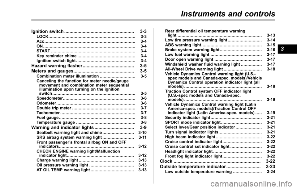
Ignition switch..................................................... 3-3LOCK.................................................................. 3-3Acc ..................................................................... 3-4ON ...................................................................... 3-4START ................................................................ 3-4Key reminder chime............................................ 3-4Ignition switch light............................................. 3-4
Hazard warning flasher....................................... 3-5
Meters and gauges.............................................. 3-5Combination meter illumination........................... 3-5Canceling the function for meter needle/gaugemovement and combination meter sequentialillumination upon turning on the ignitionswitch............................................................... 3-5Speedometer....................................................... 3-6Odometer............................................................ 3-6Double trip meter................................................ 3-7Tachometer......................................................... 3-7Fuel gauge.......................................................... 3-8Temperature gauge............................................. 3-8
Warning and indicator lights.............................. 3-9Seatbelt warning light and chime........................ 3-10SRS airbag system warning light........................ 3-11Front passenger’s frontal airbag ON and OFFindicators......................................................... 3-12CHECK ENGINE warning light/Malfunctionindicator light................................................... 3-12Charge warning light.......................................... 3-13Oil pressure warning light.................................. 3-13AT OIL TEMP warning light................................. 3-13
Rear differential oil temperature warninglight................................................................ 3-13Low tire pressure warning light.......................... 3-14ABS warning light.............................................. 3-15Brake system warning light................................ 3-16Low fuel warning light....................................... 3-17Door open warning light.................................... 3-17Windshield washer fluid warning light................ 3-17All-Wheel Drive warning light ............................. 3-18Vehicle Dynamics Control warning light (U.S.-spec models and Canada-spec. models)/VehicleDynamics Control operation indicator light (allmodels)........................................................... 3-18Traction Control system OFF indicator light(U.S.-specmodels and Canada-spec.models)........................................................... 3-19Vehicle Dynamics Control warning light (LatinAmerica-spec. models)/Traction Control OFFindicator light (Latin America-spec. models)..... 3-19Security indicator light....................................... 3-21SPORT mode indicator light............................... 3-21Select lever/Gear position indicator.................... 3-21Turn signal indicator lights................................. 3-21High beam indicator light................................... 3-22Cruise control indicator light.............................. 3-22Cruise control set indicator light........................ 3-22Headlight indicator light..................................... 3-22Front fog lightindicator light.............................. 3-22
Clock.................................................................. 3-22
Outside temperature indicator.......................... 3-23Low outside temperature warning...................... 3-24
Instruments and controls
3
Page 155 of 426
3-22Instruments and controls
&High beam indicator
light
This light shows that the headlights are inthe high beam mode.
This indicator light also illuminates whenthe headlight flasher is operated.
&Cruise control indica-
tor light
This light illuminates when the“CRUISE”main switch is pressed to activate thecruise control function. For details, refer to“To set cruise control”F7-30.
CAUTION
If the CHECK ENGINE warning light/malfunction indicator light illumi-nates, the cruise control indicatorlight flashes at the same time. Atthis time, avoid driving at highspeed and have your vehicle in-spected at a SUBARU dealer assoon as possible.
NOTE
If you move the cruise control lever orpress the main switch button whileturning the ignition switch“ON”, thecruise control function is deactivated
and the cruise control indicator lightflashes. To reactivate the cruise controlfunction, turn the ignition switch backto the“Acc”or“LOCK”position, andthen turn it again to the“ON”position.
&Cruise control set in-
dicator light
This light illuminates when vehicle speedhasbeen set to use the cruise controlfunction.
&Headlight indicator
light
This indicator light illuminates when thelight switch is turned to the“”position(to turn on the parking lights) or to the“”position (to turn on the headlights).
&Front fog light indicator
light
This indicator light illuminates while thefront fog lights are illuminated.
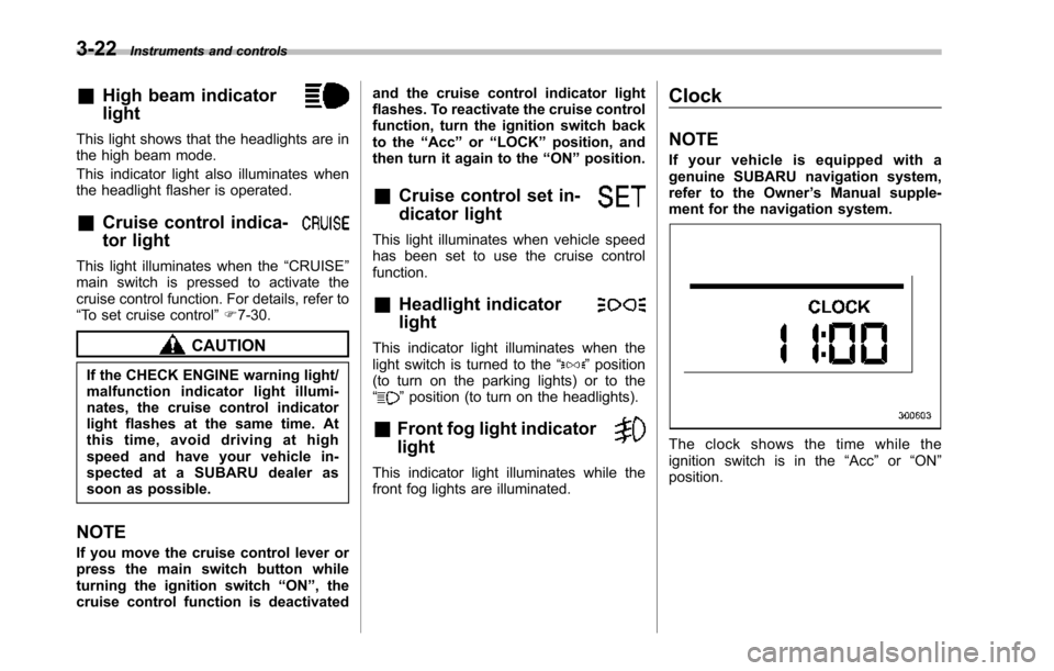
Clock
NOTE
If your vehicle is equipped with agenuine SUBARU navigation system,refer to the Owner’s Manual supple-ment for the navigation system.
The clock shows the time while theignition switch is in the“Acc”or“ON”position.
Page 156 of 426
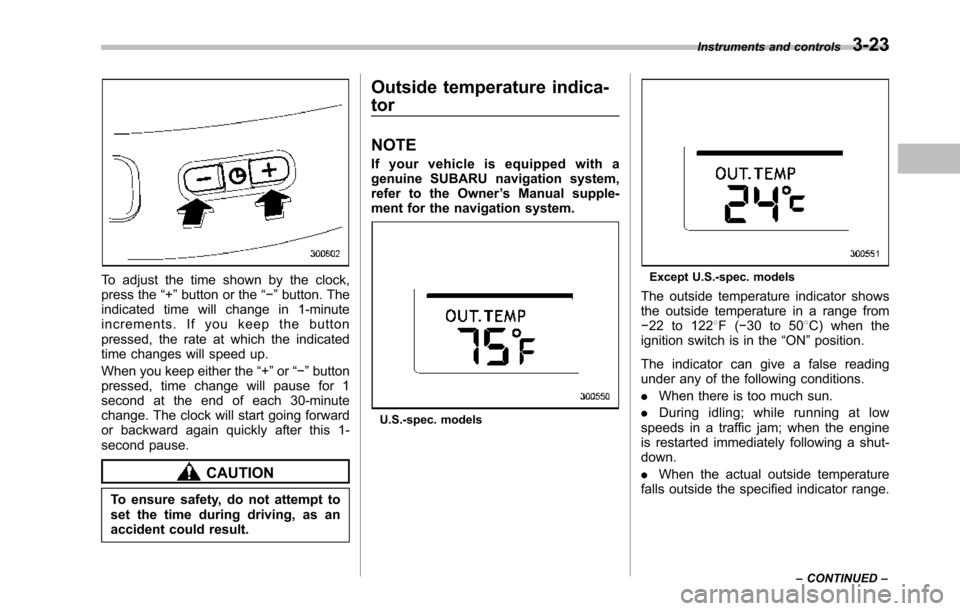
To adjust the time shown by the clock,press the“+”button or the“!”button. Theindicated time will change in 1-minuteincrements. If you keep the buttonpressed, the rate at which the indicatedtime changes will speed up.
When you keepeither the“+”or“!”buttonpressed,time change will pause for 1second at the end of each 30-minutechange. The clock will start going forwardor backward again quickly after this 1-second pause.
CAUTION
To ensure safety, do not attempt toset the time during driving, as anaccident could result.
Outside temperature indica-
tor
NOTE
If your vehicle is equipped with agenuine SUBARU navigation system,refer to the Owner’s Manual supple-ment for the navigation system.
U.S.-spec. models
Except U.S.-spec. models
Theoutside temperature indicator showsthe outside temperature in a range from!22 to 1228F(!30 to 508C) when theignition switch is in the“ON”position.
The indicator can give a false readingunder any of the following conditions.
.When there is too much sun.
.During idling; while running at lowspeeds in a traffic jam; when the engineis restarted immediately following a shut-down.
.When the actual outside temperaturefalls outside the specified indicator range.
Instruments and controls3-23
–CONTINUED–
Page 183 of 426

4-6Climate control
!OFF button
The Automatic Climate Control systemturns off (the air conditioner compressorand fan turn off) when the“OFF”button ispressed.
When the“OFF”button is pressed, theoutside airintroduction mode (air inletselection OFF) is automatically selected.
!Temperature control dial
Driver’s side
Passenger’s side
It is possible to make separate tempera-ture settings for the driver’ssideandpassenger’sside.Eachtemperature
setting is shown on the display. With thedial set at your desired temperature, thesystem automatically adjusts the tempera-ture of air supplied from the outlets suchthat the desired temperature is achievedand maintained.
Turning the dial counterclockwise andreleasing it reduces the temperature by18F (0.58C). Turning the dial clockwiseand releasing it increases the temperatureby 18F (0.58C). Holdingthe dial in eitherturnedposition causes the temperature tochange continuously.
With the minimum temperature set, thesystemgives maximum cooling perfor-mance. With the maximum temperatureset, the system gives maximum heatingperformance.
Page 312 of 426

of the tire facing up).
3. Turn the hoist shaft end clockwise withthe wheel nut wrench to wind the cable upcompletely until you hear a few clickingsounds.Confirm that the temporary sparetire holding cable has been wound upcompletely by shaking the temporary tire.
CAUTION
If the temporary spare tire is notstored securely, it could damageadjacent areas of the vehicle andmake an abnormal noise.
4. Place the wheel nut wrench andextension back into the tool bag and storethe jackand tool bag in their storagelocations.
5. Fit the lid of the cargo area.
CAUTION
.When stowing a flat tire in thespare tire holder, turn the hoistshaft end only slowly. If it isturned quickly, the wheel disc ofthe flat tire could be damaged.
.Afull-sizeflattireshouldbestowed in the spare tire holderin an emergency only. After hav-ingthe flat tire repaired, immedi-ately swap it with the temporaryspare tire.
.Remember that the tread width ofa flat tire is wider than that of thetemporary spare tire. When car-rying a flat tire stowed in thespare tire holder, make sure thetiredoes not touch any obsta-cles.
Temporary spare tire
WARNING
.Never tow a trailer when thetemporary spare tire is used.The temporary spare tire is notdesigned to sustain the towingload. Use of the temporary sparetire when towing can result infailure of the spare tire and/orless stability of the vehicle andmay lead to an accident.
.When a spare tire is mounted or awheel rim is replaced without theoriginal pressure sensor/trans-mitter being transferred, the lowtire pressure warning light willilluminate steadily after blinkingfor approximately one minute.This indicates the tire pressuremonitoring system (TPMS) is un-able to monitor all four roadwheels. Contact your SUBARUdealer as soon as possible fortire and sensor replacement and/or system resetting.
In case of emergency9-5
–CONTINUED–
Page 316 of 426
WARNING
Do not use oil or grease on thewheel studs or nuts when the sparetire is installed. This could cause thenuts to become loose and lead to anaccident.
15. Turn the jack handle counterclockwiseto lower the vehicle.
CAUTION
There are 2 types of wheel nutwrenches that apply to differentlengths.
For models with silver-colored alu-minumwheels, the 10.8-inch (275mm) wheel nut wrench is equippedas a maintenance tool. And formodels with optional chrome-fin-ished wheels, the 13.2-inch (335mm) wheel nut wrench is equippedas well. Confirm the equipped wheelnut wrench type when you replace atire. If the wheel nut wrench is thedifferent type, it cannot be tightenedto the specified torque.
1) The length of the wheel nut wrench
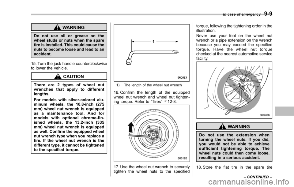
16. Confirm the length of the equippedwheel nut wrench and wheel nut tighten-ing torque. Refer to“Tires”F12-8.
17. Use the wheel nut wrench to securelytighten thewheel nuts to the specified
torque, following the tightening order in theillustration.
Never use your foot on the wheel nutwrench or a pipe extension on the wrenchbecause you may exceed the specifiedtorque. Have the wheel nut torquechecked at the nearest automotive servicefacility.
WARNING
Do not use the extension whenturning the wheel nuts. If you did,you would not be able to achievesufficient tightening torque. Thewheel nuts could then come loose,resulting in a serious accident.
18. Store the flat tire in the spare tire
In case of emergency9-9
–CONTINUED–
Page 371 of 426
11-38Maintenance and service
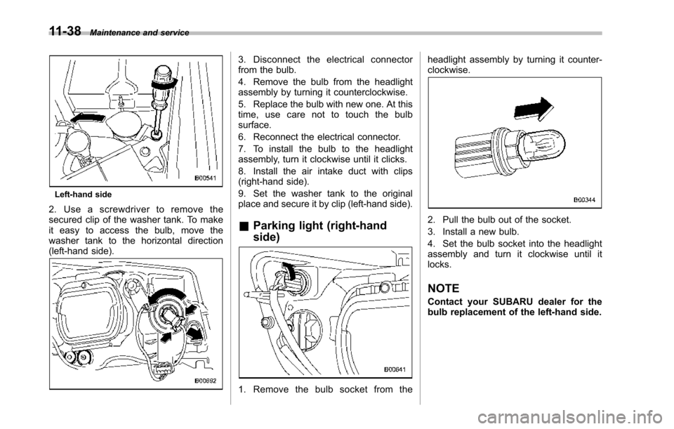
Left-hand side
2. Use a screwdriver to remove thesecured clip of the washer tank. To makeit easy to access the bulb, move thewasher tank to the horizontal direction(left-hand side).
3. Disconnect the electrical connectorfrom the bulb.
4. Remove the bulb from the headlightassembly by turning it counterclockwise.
5. Replace the bulb with new one. At thistime, use care not to touch the bulbsurface.
6. Reconnect the electrical connector.
7. To install the bulb to the headlightassembly, turn it clockwise until it clicks.
8. Install the air intake duct with clips(right-hand side).
9. Set the washer tank to the originalplace andsecure it by clip (left-hand side).
&Parking light (right-hand
side)
1. Remove the bulb socket from the
headlight assembly by turning it counter-clockwise.
2. Pull the bulb out of the socket.
3. Install a new bulb.
4. Set the bulb socket into the headlightassembly and turn it clockwise until itlocks.
NOTE
Contact your SUBARU dealer for thebulb replacement of the left-hand side.
Page 372 of 426
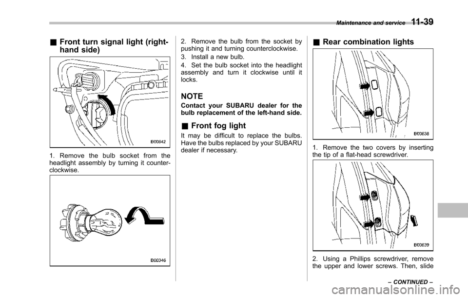
&Front turn signal light (right-
hand side)
1. Remove the bulb socket from theheadlight assembly by turning it counter-clockwise.
2. Remove the bulb from the socket bypushing it and turning counterclockwise.
3. Install a new bulb.
4. Set the bulb socket into the headlightassembly and turn it clockwise until itlocks.
NOTE
Contact your SUBARU dealer for thebulb replacement of the left-hand side.
&Front fog light
It may be difficult to replace the bulbs.Have the bulbs replaced by your SUBARUdealer if necessary.
&Rear combination lights
1. Remove the two covers by insertingthe tip of a flat-head screwdriver.
2. Using a Phillips screwdriver, removethe upper and lower screws. Then, slide
Maintenance and service11-39
–CONTINUED–