2014 SUBARU TRIBECA air conditioning
[x] Cancel search: air conditioningPage 173 of 426
3-40Instruments and controls
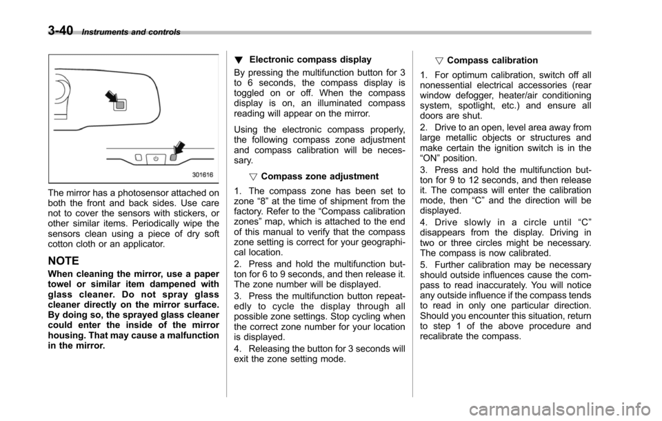
The mirror has a photosensor attached onboththe front and back sides. Use carenot to cover the sensors with stickers, orother similar items. Periodically wipe thesensors clean using a piece of dry softcotton cloth or an applicator.
NOTE
When cleaning the mirror, use a papertowel or similar item dampened withglass cleaner. Do not spray glasscleaner directly on the mirror surface.By doing so, the sprayed glass cleanercould enter the inside of the mirrorhousing. That may cause a malfunctionin the mirror.
!Electronic compass display
By pressing the multifunction button for 3to 6 seconds, the compass display istoggled on or off. When the compassdisplay is on, an illuminated compassreading will appear on the mirror.
Using the electronic compass properly,the following compass zone adjustmentand compass calibration will be neces-sary.
!Compasszone adjustment
1. The compass zone has been set tozone“8”at the time of shipment from thefactory. Refer to the“Compass calibrationzones”map, which is attached to the endof this manual to verify that the compasszone setting is correct for your geographi-cal location.
2. Press and hold the multifunction but-ton for 6 to 9 seconds, and then release it.The zone number will be displayed.
3. Press the multifunction button repeat-edly to cycle the display through allpossible zone settings. Stop cycling whenthe correct zone number for your locationis displayed.
4. Releasing the button for 3 seconds willexitthe zone setting mode.
!Compass calibration
1. For optimum calibration, switch off allnonessential electrical accessories (rearwindow defogger, heater/air conditioningsystem, spotlight, etc.) and ensure alldoors are shut.
2. Drive to an open, level area away fromlarge metallic objects or structures andmake certain the ignition switch is in the“ON”position.
3. Press and hold the multifunction but-ton for 9 to 12 seconds, and then releaseit. The compass will enter the calibrationmode,then“C”and the direction will bedisplayed.
4. Drive slowly in a circle until“C”disappears from the display. Driving intwo or three circles might be necessary.The compass is now calibrated.
5. Further calibration may be necessaryshould outside influences cause the com-pass to read inaccurately. You will noticeany outside influence if the compass tendsto read in only one particular direction.Shouldyou encounter this situation, returnto step 1 of the above procedure andrecalibrate the compass.
Page 174 of 426
&Type C inside mirror (if
equipped)
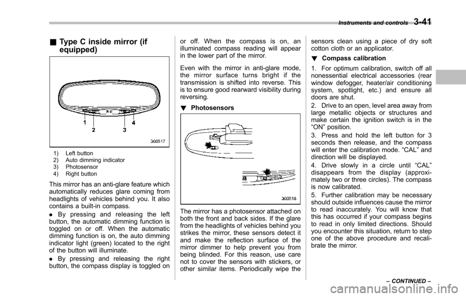
1) Left button2) Auto dimming indicator3) Photosensor4) Right button
This mirror has an anti-glare feature whichautomatically reduces glare coming fromheadlights of vehicles behind you. It alsocontains a built-in compass.
.By pressing and releasing the leftbutton, the automatic dimming function istoggled on or off. When the automaticdimming function is on, the auto dimmingindicator light (green) located to the rightof the button will illuminate.
.By pressing and releasing the rightbutton, the compass display is toggled on
or off. When the compass is on, anilluminated compass reading will appearin the lower part of the mirror.
Even with the mirror in anti-glare mode,the mirror surface turns bright if thetransmission is shifted into reverse. Thisis to ensure good rearward visibility duringreversing.
!Photosensors
The mirror has a photosensor attached onboth the front and back sides. If the glarefrom the headlights of vehicles behind youstrikes the mirror, these sensors detect itand make the reflection surface of themirror dimmer to help prevent you frombeing blinded. For this reason, use carenot to cover the sensors with stickers, orother similar items. Periodically wipe the
sensors clean using a piece of dry softcotton cloth or an applicator.
!Compass calibration
1. For optimum calibration, switch off allnonessential electrical accessories (rearwindow defogger, heater/air conditioningsystem, spotlight, etc.) and ensure alldoors are shut.
2. Drive to an open, level area away fromlarge metallic objects or structures andmake certain the ignition switch is in the“ON”position.
3. Press and hold the left button for 3seconds then release, and the compasswill enter the calibration mode.“CAL”anddirection will be displayed.
4. Drive slowly in a circle until“CAL”disappears from the display (approxi-mately two or three circles). The compassis now calibrated.
5. Further calibration may be necessaryshould outside influences cause the mirrorto read inaccurately. You will know thatthis has occurred if your compass beginsto read in only limited directions. Shouldyou encounter this situation, return to stepone of the above procedure and recali-brate the mirror.
Instruments and controls3-41
–CONTINUED–
Page 178 of 426
Ventilator.............................................................. 4-2Airflow................................................................ 4-2Ventilator............................................................ 4-4
Automatic climate control system..................... 4-5Control panel...................................................... 4-5Rear air conditioner............................................. 4-9Temperature sensors........................................... 4-9
Operating tips for heater and airconditioner....................................................... 4-10Cleaning ventilator grille..................................... 4-10Efficient cooling after parking in directsunlight........................................................... 4-10
Lubrication oil circulation in the refrigerantcircuit.............................................................. 4-10Checking air conditioning system before summerseason............................................................ 4-10Cooling and dehumidifying in high humidity andlow temperature weather conditions................. 4-10Air conditioner compressor shut-off when engineis heavily loaded.............................................. 4-11Refrigerant for your climate control system ........ 4-11
Air filtration system........................................... 4-11Replacing the air filter........................................ 4-11
Climate control
4
Page 187 of 426
4-10Climate control
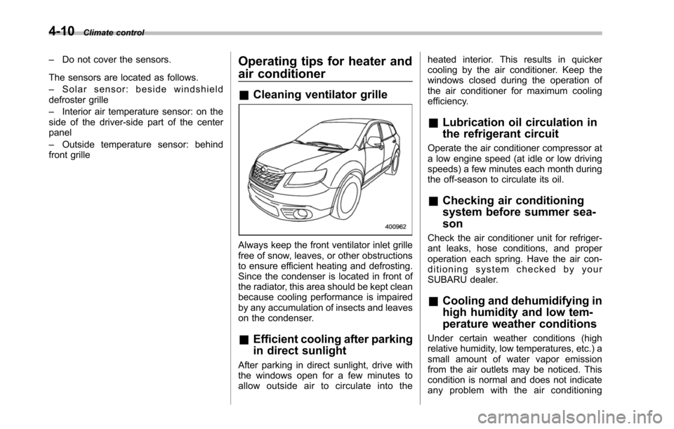
–Do not cover the sensors.
The sensors are located as follows.
–Solar sensor: beside windshielddefroster grille
–Interior air temperature sensor: on theside of the driver-side part of the centerpanel
–Outside temperature sensor: behindfront grille
Operating tips for heater and
air conditioner
&Cleaning ventilator grille
Always keep the front ventilator inlet grillefree of snow, leaves, or other obstructionsto ensure efficient heating and defrosting.Since the condenser is located in front ofthe radiator, this area should be kept cleanbecause cooling performance is impairedby any accumulation of insects and leaveson the condenser.
&Efficient cooling after parking
in direct sunlight
After parking in direct sunlight, drive withthe windows open for a few minutes toallow outside air to circulate into the
heated interior. This results in quickercooling by the air conditioner. Keep thewindows closed during the operation ofthe air conditioner for maximum coolingefficiency.
&Lubrication oil circulation in
the refrigerant circuit
Operate the air conditioner compressor ata low engine speed (at idle or low drivingspeeds) a few minutes each month duringthe off-season to circulate its oil.
&Checking air conditioning
system before summer sea-
son
Check the air conditioner unit for refriger-ant leaks,hose conditions, and properoperation each spring. Have the air con-ditioning system checked by yourSUBARU dealer.
&Cooling and dehumidifying in
high humidity and low tem-
perature weather conditions
Under certain weather conditions (highrelative humidity, low temperatures, etc.) asmall amount of water vapor emissionfrom the air outlets may be noticed. Thiscondition is normal and does not indicateany problem with the air conditioning
Page 257 of 426
7-10Starting and operating
transmitter within a few seconds immedi-ately following remote engine start shut-down.
&Pre-heating or pre-cooling
the interior of the vehicle
Before exiting the vehicle, set the tem-perature controls to the desired settingand operation. After the system starts thevehicle, the heater or air-conditioning willactivate and heat or cool the interior toyour setting.
&Service mode
In service mode, the remote start functionis temporarily disabled to prevent thesystem from unexpectedly starting theengine while being serviced.
!To engage the service mode
Turn the ignition switch to the“ON”position, depress and hold the brake pedalthen, press and release the“”button onthe remote engine start transmitter threetimes. The system will pause for 1 secondand then flash the parking lights and honkthe hornthree times indicating that thesystem is in service mode. When attempt-ing to activate the remote start systemwhile in service mode, the parking lightswill flash and the horn will honk two timesand will not start.
!To disengage the service mode
Turn the ignition switch to the“ON”position, depress and hold the brakepedal, then press and release the“”button on the remote engine start trans-mitter three times. The system will pausefor 1 second and flash the parking lightsone time indicating that the system hasexited service mode.
NOTE
When taking your vehicle in for service,it is recommended that you inform theservice personnel that your vehicle isequippedwith a remote engine startsystem.
&Remote engine start trans-
mitter programming and pro-
grammable feature option
New transmitters can be programmed tothe remote engine start system in theevent that remote engine start transmittersare lost, stolen or damaged. The remoteengine start system also has one pro-grammable feature that can be adjustedfor user preference.
The remote engine start system can beprogrammed to either make an audiblehorn chirp upon remote start activation ornot. Remote engine start transmitter pro-gramming and feature programming can
be adjusted using the following procedure.
1. Open the driver’s door (the driver’sdoor must remain opened throughout theentire process).
2. Insert the key into the vehicle’s ignitionswitch and turn to the“ON”position.
3. Locate the small black programmingbutton behind the fuse box cover, on thedriver’s side left under the dashboardpanel.
4. Press and hold the black programmingbutton for 10 to 15 seconds. The horn willhonk and the parking lights will flash threetimes to indicate that the system hasentered programming mode. At this pointyou can perform either action (step 5 orstep 6).
5. To program a remote transmitter:press and release the“”button on eachtransmitter. The horn will honk and theparking lights will flash one time to indicatea successful transmitter learn each timethe“”button is pressed. You canprogram up to eight transmitters.
6. To toggle the Horn Confirmation chirpsON/OFF: press and release the brake totoggle the feature. The horn will chirp andthe parking lights will flash one time toindicate Confirmation Horn Chirps are“OFF”. The horn will honk and the parkinglights will flash 2 times to indicate Con-firmation Horn Chirps are“ON”. Depres-
Page 399 of 426
13-6Consumer information and Reporting safety defects
sidewall rubber which, when in-
flated, bears the load.
.Chunking
The breaking away of pieces of the
tread or sidewall.
.Cold tire pressure
The pressure in a tire that has been
driven less than 1 mile or has been
standing for three hours or more.
.Cord
The strands forming the plies in the
tire.
.Cordseparation
The parting of cords from adjacent
rubber compounds.
.Cracking
Any parting within the tread, side-
wall, or inner liner of the tire
extending to cord material.
.Curb weight
The weight of a motor vehicle with
standard equipment including the
maximum capacity of fuel, oil and
coolant, and if so equipped, air
conditioning and additional weight
optional engine.
.Extra load tire
A tire designed to operate at higher
loads and higher inflation pressure
than the corresponding standard
tire.
.Groove
The space between two adjacent
tread ribs.
.Innerliner
The layer(s) forming the inside sur-
face of a tubeless tire that contains
the inflating medium within the tire.
.Innerliner separation
The parting of the innerliner from
cord material in the carcass.
.Intended outboard sidewall(1)The sidewall that contains a
whitewall, bears white lettering
or bears manufacturer, brand,
and/or model name molding that
is higher or deeper than the
same molding on the other side-
wall of the tire, or
(2)The outward facing sidewall
of an asymmetrical tire that has
a particular side that must al-
ways face outward when mount-
ing on a vehicle.
.Light truck (LT) tire
A tire designated by its manufac-
turer as primarily intended for use
on lightweight trucks or multipur-
pose passenger vehicles.
.Load rating
The maximum load that a tire is
rated to carry for a given inflation
pressure.
.Maximum inflation pressure
The maximum cold inflation pres-
sure to which a tire may be inflated.
.Maximum load rating
The load rating for a tire at the
maximum permissible inflation
pressure for that tire.
.Maximum loaded vehicle weight
The sum of:
(a)Curb weight(b)Accessory weight(c)Vehicle capacity weight(d)Production options weight.Maximum permissible inflation
pressure
The maximum cold inflation pres-
sure to which a tire may be inflated.