2014 SUBARU TRIBECA rear view mirror
[x] Cancel search: rear view mirrorPage 82 of 426

WARNING
Do not attach accessories to thewindshield, or fit an extra-wide mir-ror over the rear view mirror. If theSRS airbag deploys, those objectscould become projectiles that couldseriouslyinjure vehicle occupants.
!Driver’s SRS frontal airbag
The driver’s SRS frontal airbag uses adual stage inflator. The inflator operates indifferent ways depending on the severityof impact, backward-forward adjustmentof the driver’s seat position and whether ornot he/she is wearing the seatbelt.
The backward-forward adjustment of thedriver’s seat position is monitored by the
driver’s seat position sensor under thedriver’s seat.
Whether or not the driver is wearing theseatbelt is monitored by the seatbeltbuckle switch.
Observe the following precautions. Failureto do so may cause the seatbelt buckleswitch and/or the seat position sensor tomalfunction,preventing the SUBARU ad-vanced frontal airbag system from func-tioning correctly or causing the system tofail.
.Do not place articles/metal objects orinstall any accessory other than a genuineSUBARU accessory under the driver’sseat. Do not allow the rear seat occupantto kick the driver’s seat or push up itsbottom surface with his/her feet.
.Do not place a magnet near theseatbelt buckle or under the driver’s seat.
If the seatbelt buckle switch and/or thedriver’s seat position sensor have failed,the SRS airbag system warning light willilluminate. Although the driver’sSRSfrontal airbag can deploy regardless ofthe backward-forward adjustment of thedriver’sseatpositionevenwhenthewarning light illuminates, have the systeminspected by your SUBARU dealer im-mediatelyif the SRS airbag system warn-ing light illuminates.
NOTE
The driver’sSRSsideairbag,SRScurtain airbag and seatbelt preten-sioner are not controlled by theSUBARU advanced frontal airbag sys-tem.
!Front passenger’s SRS frontal air-bag
The front passenger’s SRS frontal airbaguses a dual stage inflator. The inflatoroperates in different ways depending onthe severity of impact.
The total load on the seat is monitored bythe occupant detection system’s weightsensor located under the seat.
The system has another sensor thatmonitors the tension of the front passen-ger seatbelt. Using the total seat load andseatbelt tension data from the sensors,the occupant detection system determineswhether the front passenger’s SRS frontalairbag should or should not be inflated.
The occupant detection system may notinflate the front passenger’s SRS frontalairbag even when the driver’s SRS frontalairbagdeploys. This is normal.
Observe the following precautions. Failureto do so may prevent the SUBARUadvanced frontal airbag system fromfunctioning correctly or cause the systemto fail.
Seat, seatbelt and SRS airbags1-51
–CONTINUED–
Page 171 of 426
3-38Instruments and controls
NOTE
The outside mirror defogger also oper-ates while the rear window defogger isoperating.
Mirrors
Always check that the inside and outsidemirrors are properly adjusted before youstart driving.
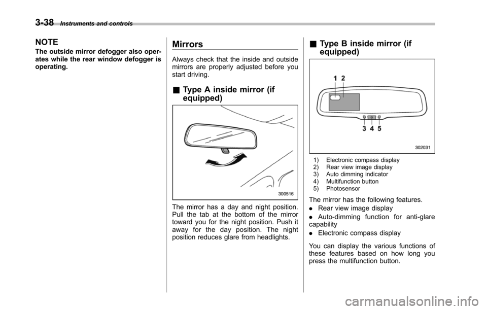
&Type A inside mirror (if
equipped)
The mirror has a day and night position.Pull the tab at the bottom of the mirrortoward you for the night position. Push itaway for the day position. The nightposition reduces glare from headlights.
&Type B inside mirror (if
equipped)
1) Electronic compass display2) Rear view image display3) Auto dimming indicator4) Multifunction button5) Photosensor
The mirror has the following features.
.Rear view image display
.Auto-dimming function for anti-glarecapability
.Electronic compass display
You can display the various functions ofthese features based on how long youpress the multifunction button.
Page 172 of 426
Gearposition
Period oftime multi-functionbutton ispressed
Functiondisplayed
R (reverse)
BrieflyRear view displayON/OFF*
More than3 secondsHelp lines indica-tion ON/OFF
ExceptR (reverse)BrieflyAuto-dimmingfunction ON/OFF*
3 to 6secondsElectronic com-pass display ON/OFF
6 to 9secondsEnterthe com-pass zone settingmode
9 to 12secondsEnter the com-passcalibrationmode
*: The setting returns to“ON”as a defaultsetting every time theignition switch is turned tothe“ON”position.
!Rear view image display
When the ignition switch is“ON”and theselect lever is set to“R”, the rear viewcamera automatically displays the rearview image behind the vehicle on theinside mirror.
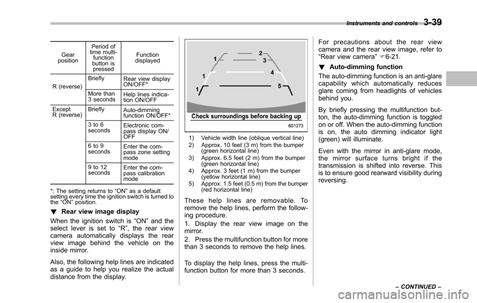
Also, the following help lines are indicatedas a guide to help you realize the actualdistance from the display.
1) Vehicle width line (oblique vertical line)2) Approx. 10 feet (3 m) from the bumper(green horizontal line)3) Approx. 6.5 feet (2 m) from the bumper(green horizontal line)4) Approx. 3 feet (1 m) from the bumper(yellow horizontal line)5) Approx. 1.5 feet (0.5 m) from the bumper(red horizontal line)
These help lines are removable. Toremove the help lines, perform the follow-ing procedure.
1. Display the rear view image on themirror.
2. Press the multifunction button for morethan 3 seconds to remove the help lines.
To display the help lines, press the multi-function button for more than 3 seconds.
For precautions about the rear viewcamera and the rear view image, refer to“Rear view camera”F6-21.
!Auto-dimming function
The auto-dimming function is an anti-glarecapability which automatically reducesglare coming from headlights of vehiclesbehind you.
By briefly pressing the multifunction but-ton, the auto-dimming function is toggledon or off. When the auto-dimming functionis on, the auto dimming indicator light(green) will illuminate.
Even with the mirror in anti-glare mode,the mirror surface turns bright if thetransmissionis shifted into reverse. Thisis to ensure good rearward visibility duringreversing.
Instruments and controls3-39
–CONTINUED–
Page 222 of 426
Interior light......................................................... 6-2Dome light.......................................................... 6-2Cargo area light.................................................. 6-3Rear gate light.................................................... 6-3Map light............................................................. 6-3Automatic ambient light for center console area(if equipped)...................................................... 6-4
Sun visors........................................................... 6-4Sun visor extension plate.................................... 6-5Vanity mirror with light........................................ 6-5
Storage compartment......................................... 6-6Glove box........................................................... 6-6Center console box............................................. 6-6Rear console....................................................... 6-7Overhead console............................................... 6-8
Cupholder........................................................... 6-8Front passenger’s cup holder.............................. 6-8Second-row seat cup holders.............................. 6-9Third-row seat cup holders.................................. 6-9
Bottle holders...................................................... 6-9
Accessory power outlets................................... 6-10
Coat hook........................................................... 6-12
Shopping bag hook............................................ 6-13
Floor mat............................................................ 6-13
Cargo area cover (if equipped)......................... 6-14Using the cover................................................. 6-14To remove the cover.......................................... 6-15To install the cover housing............................... 6-15
Convenient tie-down hooks.............................. 6-16
Under-floor storage compartment.................... 6-16
HomeLink®Wireless Control System (ifequipped)........................................................ 6-17Garage door opener programming in theU.S.A............................................................... 6-18Programming rolling-code-protected garage dooropeners in the U.S.A........................................ 6-19Programmingfor entrance gates and garage dooropeners in Canada........................................... 6-20Programming other devices............................... 6-21Operating the HomeLink®Wireless ControlSystem............................................................ 6-21ErasingHomeLink®button memory.................... 6-21In case a problem occurs................................... 6-21
Rear view camera (if equipped)........................ 6-21How to use the rear view camera....................... 6-22Viewing range on the screen.............................. 6-23Help line............................................................ 6-24
Interior equipment
6
Page 226 of 426
&Sun visor extension plate
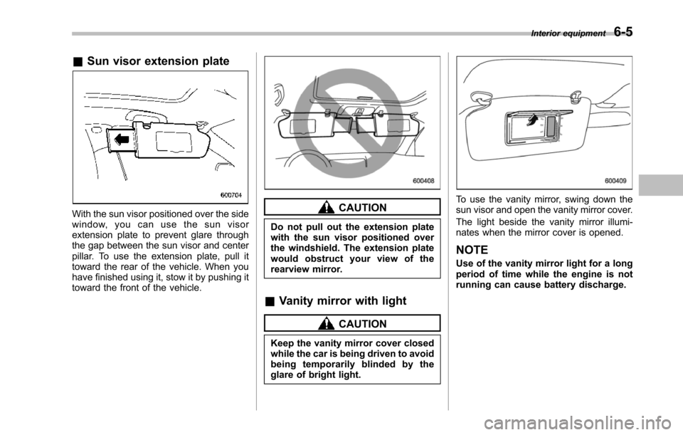
With the sun visor positioned over the sidewindow, you can use the sun visorextension plate to prevent glare throughthe gap between the sun visor and centerpillar. To use the extension plate, pull ittoward the rear of the vehicle. When youhave finished using it, stow it by pushing ittoward the front of the vehicle.
CAUTION
Do not pull out the extension platewith the sun visor positioned overthe windshield. The extension platewould obstruct your view of therearview mirror.
&Vanity mirror with light
CAUTION
Keep the vanity mirror cover closedwhile the car is being driven to avoidbeing temporarily blinded by theglare of bright light.
To use the vanity mirror, swing down thesun visor and open the vanity mirror cover.
The light beside the vanity mirror illumi-nates when the mirror cover is opened.
NOTE
Use of the vanity mirror light for a longperiod of time while the engine is notrunning can cause battery discharge.
Interior equipment6-5
Page 242 of 426
opener by pressing the programmedHomeLink®button.
&Programming other devices
To program other devices such as doorlocks, home lighting and security systems,contact HomeLink at www.homelink.comor call 1-800-355-3515.
&Operating the HomeLink®
Wireless Control System
Once programmed, the HomeLink®Wire-less Control System can be used toremote-controlthe devices to which itsbuttons are programmed. To activate adevice, simply press the appropriate but-ton.The indicator light illuminates, indicat-ing that the signal is being transmitted.
&Erasing HomeLink®button
memory
NOTE
.Performing this procedure erasesthe memory of all the preprogrammedbuttons simultaneously. The memoryof individual buttons cannot be erased..It is recommended that upon thesale of the vehicle, the memory of allprogrammed HomeLink®buttons beerased for security purposes.
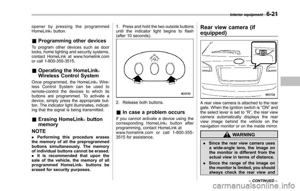
1. Press and hold the two outside buttonsuntil the indicator light begins to flash(after 10 seconds).
2. Release both buttons.
&In case a problem occurs
If you cannot activate a device using thecorresponding HomeLink®button afterprogramming, contact HomeLink atwww.homelink.com or call 1-800-355-3515 for assistance.
Rear view camera (if
equipped)
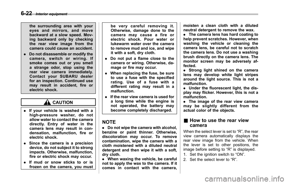
A rear view camera is attached to the reargate. When the ignition switch is“ON”andthe select lever is set to“R”, the rear viewcamera automatically displays the rearview image behind the vehicle on thenavigation monitor or on the inside mirror.
WARNING
.Since the rear view camera usesa wide-angle lens, the image onthe monitor is different from theactual view in terms of distance.
.Since the range of the image onthe monitor is limited, you shouldalways check the rear view and
Interior equipment6-21
–CONTINUED–
Page 243 of 426
6-22Interior equipment
the surrounding area with youreyes and mirrors, and movebackward at a slow speed. Mov-ing backward only by checkingthe rear view image from thecamera could cause an accident.
.Do not disassemble or modify thecamera, switch or wiring. Ifsmoke comes out or you smella strange odor, stop using therear view camera immediately.Contact your SUBARU dealerfor an inspection. Continued usemay result in accident, fire orelectric shock.
CAUTION
.If your vehicle is washed with ahigh-pressure washer, do notallow water to contact the cameradirectly. Entry of water in thecamera lens may result in con-densation, malfunction, fire orelectric shock.
.Since the camera is a precisiondevice, do not subject it to strongimpacts. Otherwise, malfunction,fire or electric shock may occur.
.If mud or snow sticks to or isfrozen on the camera, you must
be very careful removing it.Otherwise, damage done to thecamera may cause a fire orelectric shock. Pour water orlukewarm water over the camerato remove mud and ice, and wipeit with a soft, dry cloth.
.Do not put a flame close to thecamera or wiring. Otherwise, da-mage or fire may occur.
.When replacing the fuse, be sureto use a fuse with the specifiedrating. Use of a fuse with adifferent rating may result in amalfunction.
.If the rear view camera is used fora long time while the engine isnot operated, the battery maybecome completely discharged.
NOTE
.Do not wipe the camera with alcohol,benzine or paint thinner. Otherwise,discoloration may occur. To removecontamination, wipe the camera with acloth moistened with a diluted neutraldetergent and then wipe it with a soft,dry cloth..When waxing the vehicle, be carefulnot to apply the wax to the camera. If itcomes in contact with the camera,
moisten a clean cloth with a dilutedneutral detergent to remove the wax..The camera lens has hard coating tohelp prevent scratches. However, whenwashing the vehicle or cleaning thecamera lens, be careful not to scratchthe camera lens. Do not use a washingbrush directly on the camera lens. Themonitorscreen may be adversely af-fected..Strong light shined on the cameralens may develop white light stripesaround the light source. This is not amalfunction..Under the fluorescent light, the dis-play may flicker. However, this is not amalfunction..The image of the rear view cameramay be slightly different from theactual color of the objects.
&How to use the rear view
camera
When the select lever is set to“R”, the rearview camera automatically displays therear view image from the vehicle. Whenthe lever is set to other positions, theimage before setting to“R”is displayed.
1. Set the ignition switch to“ON”.
2. Set the select lever to“R”.
Page 244 of 426
NOTE
.The image of the rear view camerahas priority over other screen displays..The image of the rear view camera ishorizontally reversed as is the casewith the vehicle rearview mirror or theside view mirror..It may be difficult to see the image ofthe rearview camera in the followingcases. This is not a malfunction of thecamera.–The vehicle is in a dark place (atnight, in a tunnel, etc.).–The vehicle is in an extremely hotor cold place.–An object (such as raindrops,snow, dirt, etc.) that disturbs theview of the rear view camera sticksto the lens of the camera.–Strong light shined directly onthe camera lens (occasionally, thereare vertical lines on the screen).
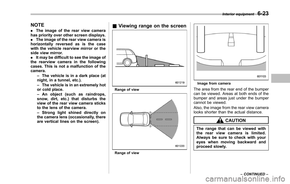
&Viewing range on the screen
Range of view
Range of view
Image from camera
Thearea from the rear end of the bumpercan be viewed. Areas at both ends of thebumper and areas just under the bumpercannot be viewed.
Also, the image from the rear view cameralooks shorter than the actual distance.
CAUTION
The rangethat can be viewed withthe rear view camera is limited.Always be sure to check with youreyes when moving backward andproceed slowly.
Interior equipment6-23
–CONTINUED–